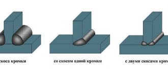
Positions by which classification is carried out
According to regulatory documents, the classification of welding seams has divisions depending on their positions, required length, direction of effort, number of passes, execution features, in particular the number of layers. There are different types of welded assemblies depending on the operating conditions. Finished seams are classified according to their width and external shape.
Position in space
The classification of welds by location offers only four options for the location of welds:
- at the bottom;
- above;
- horizontally;
- vertically.
If possible, experienced welders would choose the lower position themselves and advise beginners to do the same. The advantages of this provision are obvious, but each of the remaining options has its own characteristics when implemented. All of them are united by the main problem - the force of gravity, under the influence of which the metal begins to flow down.
The top position is otherwise called the ceiling position. In this subgroup it is considered the most difficult. It’s not worth starting with it to learn the welding profession - it will require real skill. The electrode can only be in one position - vertically upward, which is difficult in the already awkward position of the performer. Welding should be done in a circular motion at a constant speed. The arc should not be long. Despite following all the recommendations, such a seam may not always turn out to be of very high quality.
In a horizontal position, cooking is allowed both to the right and to the left. The angle of inclination of the electrode must be large enough taking into account the magnitude of the current. If there is significant metal drainage, the problem can be partially solved by increasing the speed of movement, which will reduce heating. Another option is to periodically tear off the arc, allowing time for the metal to cool.
In contrast to the horizontal position, in the vertical position, not the entire weld pool will tend downward, but only drops of metal. The seam is welded in any direction, and the arc is made short.
Length
The main gradation in length is divided into two types: continuous and intermittent. If everything is clear with the definition of continuous, then an intermittent seam is called a seam, the technology of which provides for the presence of a constant interval. An intermittent weld is in turn divided into chain, staggered and spot welds.
Welds can be made on one or both sides. The connections on the catenary tracks are opposite each other. A checkerboard weld involves welding performed in a checkerboard pattern.
GOST 5264 regulates the rules for designating a weld. The drawings should indicate whether it is in a chain or staggered arrangement. The designation contains information about the dimensions. So, a 50/100 interrupted weld means that its length is 50 mm and its pitch is 100 mm. A 100/100 weld pitch is the same size as its length. An intermittent weld with a pitch whose length is 40 mm, and a pitch of 120 will be designated 40/120.
If it is necessary to indicate the data of a non-standard weld, then its design dimensions are set in such a way that they correspond to the task. The spot method does not require a weld pool. Elements of metal products with this method are fastened using an overlap welded joint.
Direction of effort
Another group of qualifications is the division according to the direction of the efforts made.
Welds along the section are differentiated:
- With the flank or longitudinal method, the force is directed parallel to the axis of the seam.
- In the frontal or transverse version, the forces make a right angle with the axis.
- The combined method combines the first two methods.
- In the oblique version, the force is applied at an angle to the axis of the seam.
Surface shape
The classification of welded joints includes a division based on the appearance of the surface shape of the welds. There are three types:
- Normal. The name speaks for itself.
- Convex. Otherwise - reinforced.
- Concave. In other words, weakened.
Each type has advantages depending on the working conditions. Convex seams are multi-layered. They are used when the joint being fastened is to be used under static loads.
However, it should be taken into account that increased influx will lead to additional consumption of electrodes, which increases the cost of the process. Concave ones are used when sheets of thin metal are to be fastened. Under dynamic loads, it is better to use flat or concave seams, since in this case there is no large difference between the base material and the seam.
Conditions in which a unit with welded surfaces will have to operate
The division depends solely on the operating conditions of the product unit. Workers include welds who must bear loads, sometimes significant ones. Non-working seams are simply connecting or connecting seams. Naturally, there is a significant difference in the requirements placed on them. Working seams must be inspected using suitable methods.
A weld that is not operational but is exposed to adverse weather conditions must be free of voids and cracks.
Width
According to this criterion, welding seams are of two types:
- widened;
- thread
When surfacing works, a widened version is used. If you have to weld sheets of thin metal, thread seams are chosen.
Number of layers
Layers are otherwise called passes. Classification on this basis has two options
- single-layer or single-pass;
- multi-layer or multi-pass.
A multilayer welding seam has its own peculiarity - it is a seam in which the number of layers coincides with the number of passes. If some layers were made in several passes, they will be called multi-pass. The scope of application of multilayer seams is butt welding. The multi-pass option is used for fillet welds and T-shaped welds.
With the multi-pass method, the next layer is applied to the previous one that has not cooled down. Before doing this, you need to quickly remove the welding slag. If welding is carried out on a section with a length of 200 mm, then it is carried out in different directions. When applying the next layer, annealing occurs in the previous one, which has a positive effect on the structure and mechanical characteristics of the weld.
Nature of execution
According to the nature of execution, welds are divided into one-sided and two-sided.
A single-sided seam is located on one side, and a double-sided seam is located on both sides.
Examples of symbols
To make it clearer for you and you can quickly understand all the notations, we will give several simple and illustrative examples. So, let's begin.
Example No. 1
In the picture above you see a butt seam in which one edge has a curved bevel. The connection itself is double-sided, made by manual arc welding. There is no gain on either side. On the front side the seam roughness is Rz 20 µm, and on the back side it is Rz 80 µm.
Example No. 2
Here you can see that the seam is corner and double-sided, it has no bevels or edges. This connection is made by automatic welding and using flux.
Example No. 3
Here we have a butt seam again, but without bevels or edges. The connection is one-sided, with a lining. The seam is made using heated gas and welding wire.
Example No. 4
In the fourth example, the seam is a T-joint and has no bevels or edges. It is intermittent and performed using a bilateral method. The seam seems to be in a checkerboard pattern. The work was performed using RDS in a gas environment and using a non-consumable metal rod. The leg of the seam is 6 millimeters, and the length of the seam is 50 millimeters, in increments of 100 millimeters (indicated by the letter “Z”). t w is the length of the seam, and t pr is the length of the step of the intermittent connection.
Example No. 5
In our last example, the seam is overlapped and has no bevels or edges. It is also single-sided and is performed by manual gas-shielded arc welding using a consumable rod. The welded connection is made along an open line. The leg of the seam is 5 millimeters.
Additional technologies
Welding connections can be made using various additional technologies. The main types include the following:
- Podvarochny . Pre-seam. Prevents burns during the main process.
- Potholder . Fixes parts prepared for the welding process.
- Temporary . It holds the workpieces together for the required time and then removes them.
- Installation weld . It is used for installation of all kinds of structures.
Additional technologies facilitate the main process and increase the positive characteristics of welds.
Auxiliary signs
In addition to arrows and letters, auxiliary symbols can be used to indicate welds. Below you can see the standard structure of the symbol, its “skeleton”, on which “muscles” should then appear in the form of letters or other signs.
Auxiliary characters include alphanumeric combinations that contain information about the type of seam and type of connection. This sounds pretty confusing, but here's a quick example: We have the designation C1 and it stands for "single-sided butt weld." C is a letter indicating the type of seam, and 1 is a number indicating the side of welding. Double-sided welding is indicated by the number 2.
Below you can see symbols of seams and joints for some welding methods.
Welding methods also have their own symbol. They are also marked with a letter, this is indicated in regulatory documents. Based on the standards, the welding process indicated on the assembly drawing is carried out.
Below you can see the main welding methods and their designations:
- Automatic submerged arc welding, without the use of flux pads and pads during operation (indicated by the letter “A”).
- Automatic submerged arc welding using a flux pad (“AF”).
- Gas shielded welding using tungsten rods and no wire (“IN”).
- Welding in a shielding gas environment using tungsten rods and using wire (INp).
- Gas shielded welding using consumable rods (“IP”).
- Welding with consumable rods in a carbon dioxide environment (“WW”).
Read also: How to connect an electric bell to your home
Types of welding
The quality of welds largely depends on the equipment used. Main welding types:
- Manual arc . This method can be used to fasten parts made of metals of any thickness.
- Automatic . The equipment required is a transformer, rectifier or inverter.
- In an inert gas . The connection is very strong. Inert gases protect metal parts from oxidation. The advantages include the absence of slag and waste, as well as a neat appearance.
- Gas . The seam is carried out under the influence of the combustion temperature of the gas from the burner.
- Using a soldering iron.
The type of welding is selected based on the requirements for the weld.
Leg selection
The surface of the weld seam at corner joints is:
- Convex - the roller protrudes outward, sometimes exceeding the length of the leg itself. Externally, such a weld looks powerful, but an increased amount of deposited metal leads to the formation of internal stresses. Because of this, the product is prone to deformation, especially if its walls are 2-3 mm.
- Concave - the surface of the seam is curved inward and located below the height of the leg. To achieve this shape, you need to increase the current and move the electrode or torch faster. On a semi-automatic machine, it is worth increasing the inductance so that the drop separation process becomes smoother. This increases the penetration depth and promotes a concave weld surface.
- Flat - between the sides of the corner joint there is an almost flat, oblique plane of the seam surface. This happens less often, but is still possible. This option is more convenient for mechanical processing of joints - it is not enough to clean off the deposited metal and the grinding machine equipment immediately captures the entire surface.
In each case, the leg means the length (on the horizontal part of the workpiece) and height (on the vertical part of the workpiece) of the side of the triangle, starting from the root of the seam. In other words, this is the distance from the edge (outer border) of the seam to the surface of another part.
It seems that the more legs, the better, but this is not so. A large leg of the weld creates stress in the joint and leads to inversion of the structure. The heating area of the part increases. The product may lead to severe damage. A large leg always means excessive consumption of material (electrodes, welding or filler wire), and a time delay. Creating a high-height weld requires holding the arc in one place for a long time, which leads to burnout of alloying elements and faster corrosion. Therefore, the leg should be calculated correctly for each design.
Type of welded joints
The main types of connections made by welding include:
- Butt . The peculiarity of the arrangement is that all parts to be welded are in the same plane.
- Angular _ The connected elements can be located relative to each other at any angle.
- Lap . The parts are located parallel to each other.
- T-bars . The end of one part and the surface of another are located at an angle.
- End _ The parts to be welded are aligned with their surfaces.
Butt welding is widely used for joining parts in sheet metal structures, pipes and tanks. The technology of welding butt joints is that two parts to be welded are connected to each other by their end surfaces. The parts must be located on the same plane.
Butt welding, as butt welding is also called, is a simple and reliable connection. It is recommended to use it in structures exposed to alternating voltage. The method provides high strength and minimal deformation. The difficulty of application is the need to carefully adjust the edges to each other. The advantages are savings in consumables and the short time required to complete the process. Special requirements apply to the selection of electrodes.
There are various methods for welding butt seams:
- Aweigh;
- lined with copper;
- on a steel lining;
- when performing a preliminary weld.
It is quite difficult to obtain good penetration of the base of the seam by hanging welding. Methods using a copper or steel backing are preferred. They must be pressed firmly against the welded edges. This will reduce the likelihood of liquid metal leaking out of the bath. The underwelding seam is made on the other side, if possible.
Small parts are welded without cutting edges. Depending on the thickness of the parts, welding can be on one side or both. The electrode performs oscillatory movements. When performing this type of welding, it is necessary to ensure that both edges melt evenly to the required depth.
The advantages of butt welding over other methods are a reduction in the consumption of electrodes and electrical resources, and ease of control of the welding process. The thickness of the parts being welded does not have to be the same. In this case, a locking connection will help to strengthen the seam.
Fillet welds can be used for welding tanks and various tanks. They have a limitation - the thickness of the metal should be no more than 3 mm. Not used in structures that experience high internal pressure. Corner joints seem simple, but even in this form there are difficulties. Metal can flow down onto a horizontal plane. To avoid this, it is necessary to constantly monitor the movements of the electrode and maintain the correct angle of its inclination.
High-quality fillet welding is obtained when using a “boat”. If metal sheets of unequal thickness are being welded, the electrode should be placed towards the thicker part to provide it with stronger heating. At the same time, this will prevent burning of thin metal. When welding using the corner method, it is necessary to comply with geometric criteria: width, curvature, convexity.
The lap joint is used for welding structures made of metal sheets up to 12 mm thick. A lap weld is a common type of welding connection. Its use is possible when the surfaces of the parts being connected fit tightly and without gaps. This ensures that parts of the elements being connected overlap. The lap welded joint is quite simple and is suitable for beginners without much experience in welding. Its use is justified in places where it is necessary to achieve high tensile strength.
The seams with this method are spaced at a certain distance, which provides additional strength. It is undesirable to use if there is a fracture load. The calculation of the load of an overlap joint takes into account all types of existing loads to ensure the required strength. The advantages of the method include ease of execution, high tensile strength, and low cost. As preparatory work, only pruning is necessary.
The T-joint resembles an inverted "T". The end of one part and the surface of the second are welded at an angle that is straight. Deviations from the angle value should be minimal. Used in welding load-bearing structures. Careful surface treatment is required. T-joints can be conveniently made in vertical and horizontal positions.
It is most convenient to carry out welding in an inclined position, using the “boat” principle. In this case, the process can be carried out in the lower position, which is an invaluable advantage. Welding speed increases and the likelihood of undercuts decreases. This type of welding is one of the most durable.
The arrangement of the elements provides additional rigidity. T-joints allow welding in hard-to-reach places. Used for welding parts of various thicknesses. With such connections, structures can withstand heavy loads.
With the end connection, the ends of the two parts are welded, and the sides fit tightly to each other. Can be used for both thin and thick materials and parts. The probability of burn-throughs is low, deformations and stresses are small. The advantages include high thermal conductivity. There are no special requirements for the surface of the ends. Execution is simple.
What does the technical abbreviation stand for?
When designating welds in the documentation, it is necessary to focus on the requirements of the ESKD, which includes: GOST 5264-80, GOST 14771-76 and GOST 2.312-72.
Conditional images of seams
Welded joints can be made visible, located on the front surfaces, and invisible, made on the wrong side of the product. In two-way connections, the one that should be done first is considered to be the front one. When arranging symmetrical edges, either side can be called the front side. Invisible seams in the drawing are indicated by dashed segments, visible ones - by solid lines.
The location of the seam line is indicated by a one-way arrow. There is a “shelf” on it with an auxiliary sign or letter designation. When indicating an invisible seam, they are placed under the “shelf”, when indicating a visible seam, they are placed above it.
A combination of letters and numbers is required, containing data on the type of welding work and the type of joint. For example, the abbreviation C1 means the use of single-sided butt fastening, C2 - double-sided.
To provide more complete information, auxiliary signs are used to describe the connections (shape of the seam (along closed/open lines), discontinuity or spot application, etc.), operations that need to be performed by the craftsman (remove the bulge, process bulges or irregularities, etc.). ).
Welding method designation
Welding methods have their own symbols, indicated on the assembly drawings.
| Designation | Work method |
| A | Submerged in automatic mode (without the use of pads and pillows) |
| Af | Submerged using automation (with pillows) |
| IN | In a cloud of protective gases with refractory tungsten electrodes (without additional materials) |
| INp | In an environment of inert gases with tungsten electrodes (with wire) |
| IP | In a cloud of protective gases melting electrodes |
| UP | In a carbon dioxide environment with consumable electrodes |
Competent and correct application of symbols in design documentation allows welding specialists to decipher the seams in the drawings and perform high-quality metal work.
Consequences of incorrect leg calculations
We have already considered the negative consequences of a large leg. The second common mistake is that the seam leg is too small. Then there is little deposited metal on the sides, which reduces the strength of the connection. If it breaks or vibrates, the structure may not withstand the load and the seam will crack. Although the small leg saves consumables, it is only acceptable for non-essential connections (barbecue, table, etc.).
Another mistake welders make is an asymmetrical leg. Most often, the bottom flange of the seam is too wide, and the top flange is too short. This happens when the technique is incorrect or the welding mode is selected, because the molten metal flows down under the influence of gravity. The seam looks wide, but only slightly extends to the vertical side, so it holds weakly and is not designed for serious loads.
APPENDIX 2 (recommended)
APPENDIX 2 Recommended
mm
| Fillet weld leg for the ratio of the tensile strength of the weld metal to the tensile strength of the base metal | ||||
| 1,0 | 1,1 | 1,2 | 1,3 | 1,4 |
| 4 | 4 | 4 | 3 | 3 |
| 5 | 5 | 4 | 4 | 4 |
| 6 | 6 | 5 | 5 | 4 |
| 7 | 7 | 6 | 6 | 5 |
| 8 | 7 | 7 | 6 | 6 |
| 9 | 8 | 8 | 7 | 7 |
| 10 | 9 | 9 | 8 | 7 |
| 11 | 10 | 9 | 9 | 8 |
| 12 | 11 | 10 | 9 | 9 |
| 13 | 12 | 11 | 10 | 9 |
| 14 | 13 | 12 | 11 | 10 |
| 15 | 14 | 13 | 12 | 11 |
| 16 | 15 | 14 | 13 | 12 |
| 17 | 16 | 14 | 13 | 12 |
| 18 | 17 | 15 | 14 | 13 |
| 19 | 17 | 16 | 15 | 14 |
| 20 | 18 | 17 | 16 | 14 |