INTERSTATE COUNCIL FOR STANDARDIZATION, METROLOGY AND CERTIFICATION (IGU)
INTERSTATE COUNCIL FOR STANDARDIZATION, METROLOGY AND CERTIFICATION (ISC)
| INTERSTATE STANDARD | GOST 14098-2014 |
WELDED CONNECTIONS OF REINFORCEMENTS AND EMBODIED PRODUCTS OF REINFORCED CONCRETE STRUCTURES
Types, designs and sizes
| Moscow Standardinform 2015 |
Preface
The goals, basic principles and basic procedure for work on interstate standardization are established by GOST 1.0-92 “Interstate standardization system. Basic provisions" and GOST 1.2-2009 "Interstate standardization system. Interstate standards, rules and recommendations for interstate standardization. Procedure for development and adoption, application, updating and cancellation"
Standard information
1 DEVELOPED by the Research Institute of Concrete and Reinforced Concrete named after. A.A. Gvozdev OJSC "Research Center "Construction"
2 INTRODUCED by the Technical Committee for Standardization TK465 “Construction”
3 ADOPTED by the Interstate Council for Standardization, Metrology and Certification (Minutes dated September 30, 2014 70-P)
The following voted for the adoption of the standard:
| Short name of the country according to MK (ISO 3166) 004-97 | Country code according to MK (ISO 3166) 004-97 | Abbreviated name of the national standardization body |
| Armenia | A.M. | Ministry of Economy of the Republic of Armenia |
| Belarus | BY | State Standard of the Republic of Belarus |
| Kyrgyzstan | KG | Kyrgyzstandard |
| Russia | RU | Rosstandart |
| Kazakhstan | KZ | Gosstandart of the Republic of Kazakhstan |
(IUS 7-2018).
4 By Order of the Federal Agency for Technical Regulation and Metrology dated October 22, 2014 No. 1374-st, the interstate standard GOST 14098-2014 was put into effect as a national standard of the Russian Federation on July 1, 2015.
5 INSTEAD GOST 14098-91
Information about changes to this standard is published in the annual information index “National Standards”, and the text of changes and amendments is published in the monthly information index “National Standards”. In case of revision (replacement) or cancellation of this standard, the corresponding notice will be published in the monthly information index “National Standards”. Relevant information, notifications and texts are also posted in the public information system - on the official website of the Federal Agency for Technical Regulation and Metrology on the Internet
INTERSTATE STANDARD
WELDED CONNECTIONS OF REINFORCEMENTS AND EMBODIED PRODUCTS OF REINFORCED CONCRETE STRUCTURES
Types, designs and sizes
Welded joints of reinforcement and inserts for reinforced concrete structures. Types, constructions and dimensions
Date of introduction - 2015-07-01
Content
- 1 area of use
- 2 Normative references
- 3 Terms and definitions
- 4 General tolerances
4.1 Tolerances of linear dimensions
- 4.2 Tolerances of angular dimensions
- 4.3 Tolerances for straightness, flatness and parallelism
- 6.1 General provisions
Appendix YES (informative) Information on compliance with reference international standards
national standards
NATIONAL STANDARD OF THE RUSSIAN FEDERATION
Welding
GENERAL TOLERANCES FOR WELDED STRUCTURES
Linear and angular dimensions.
Shape and location
Welding. General tolerances for welded constructions. Dimensions for lengths and angles. Shape and position
Date of introduction: 2017—10—01
2 Normative references
The following reference standards are required for the application of this standard. For dated references, only the edition of the referenced standard applies; for undated references, the latest edition of the referenced standard (including any amendments thereto) applies:
ISO/DIS 463 Geometrical Product Specifications (GPS) — Dimensional measuring instruments; Dial gauges — Design and metrological requirements (Geometric characteristics of products. Measuring instruments with a dial scale. Design and metrological requirements)
_________________
Replaced by ISO 463:2006 Geometric characteristics of products. Instruments for measuring dimensions. Design and metrological characteristics of mechanical instruments with a dial scale.”
prEN ISO 1101 Technical drawings — Geometrical tolerance. Tolerances of form, orientation, location and run-out - Generalities, definitions, symbols, indications on drawings
_________________
Replaced by ISO 1101:2012 “Geometric characteristics of products. Setting geometric tolerances. Tolerances of shape, orientation, location and runout.”
ISO 3599 Vernier callipers reading to 0.1 and 0.05 mm
_________________
Replaced by ISO 13385-1:2011 “Geometric characteristics of products. Instruments for measuring dimensions. Part 1. Calipers. Structural and metrological characteristics" and ISO 13385-2:2011 "Geometric characteristics of products. Instruments for measuring dimensions. Part 2. Depth gauges. Structural and metrological characteristics".
ISO 6906 Vernier callipers reading to 0.02 mm
_________________
Replaced by ISO 13385-1:2011 “Geometric characteristics of products. Instruments for measuring dimensions. Part 1. Calipers. Structural and metrological characteristics" and ISO 13385-2:2011 "Geometric characteristics of products. Instruments for measuring dimensions. Part 2. Depth gauges. Structural and metrological characteristics".
ISO 8015 Technical drawings - Fundamental tolerancing principle
Structural elements and dimensions
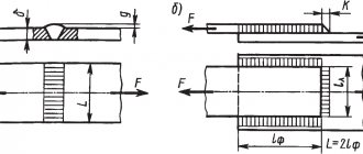
Welding method Dн b, no more than f K, no less than prepared edges of the welded parts of the weld U8 ZP 14-25 0.5 K-1 3 32-57 4 76-159 1.0 5 194 6 219 1.5 7 245 8 273-325 9 377-530 10Note. The value of “K” is determined during design.
Table 28
mm
| Symbol of welded joint | Structural elements and dimensions | Welding method | s - s1 | K | g | e | ||||
| prepared edges of welded parts | weld | Nom. | Prev. Off | Nom. | Prev. Off | Nom. | Prev. Off | |||
| U16 | Salary; | 2 | 3 | +1 | 1,5 | +1,0 | 4 | +2 | ||
| 3 | ||||||||||
| R | 4 | 4 | -0,5 | 6 | ||||||
Table 29
mm
| Symbol of welded joint | Structural elements and dimensions | Welding method | s1 | b, no more | TO | |
| prepared edges of welded parts | weld | |||||
| U17 | G | 1-7 | 1 | 1.3 thickness of thinner part | ||
| Salary; ZN; R | 2-20 | 2 | ||||
Note. The connection is used when the ratio of the outer diameter of the branch to the outer diameter of the pipe is no more than 0.5.
Table 30
mm
| Symbol of welded joint | Structural elements and dimensions | Welding method | s1 | b, no more | TO | |
| prepared edges of welded parts | weld | |||||
| U18 | G | 1-7 | 1 | 1.3 thickness of thinner part | ||
| Salary; R; ZN | 2-25 | 2 | ||||
Note. The connection is used when the ratio of the outer diameter of the branch to the outer diameter of the pipe is no more than 0.5.
Table 31
mm
| Symbol of welded joint | Structural elements and dimensions | Welding method | s1 | e | g | ||
| prepared edges of welded parts | weld | Nom. | Prev. off | +2 | |||
| U19 | Salary; | 4 | 8 | +2 | 3 | ||
| 5 | 10 | ||||||
| 6 | 11 | ||||||
| 8 | 14 | +3 | |||||
| 10 | 16 | +4 | |||||
| 12 | 19 | 5 | |||||
| ZN; | 14 | 22 | +5 | ||||
| R | 16 | 24 | +6 | ||||
| 18 | 26 | ||||||
| 20 | 28 | ||||||
| 22 | 30 | ||||||
| 25 | 33 | ||||||
Table 32
mm
| Symbol of welded joint | back to contents | |
Structural elements and dimensions
Welding method s – s1 b with eg prepared edges of the welded parts of the weld seam Nomin. Prev. off Nom. Prev. off Nom. Prev. off Nom. Prev. offC8
Salary;R
3 1 +0,5 0,5 +0,5 8 +2 1,5 +1,5 -1,0 4 10 5 11 6 12 7 13 +3 8 14 2,0 +2,0 -1,5 9 2 1,0 ±0,5 16 +4 10 18 12 +1,0 20 14 22 +5 16 25 18 27 20 29 +7Table 6
mm
| Symbol of welded joint | Structural elements and dimensions | Welding method | s–s1 | b | e | g | ||||
| prepared edges of welded parts | weld | Nom. | Prev. off | Nom. | Prev. off | Nom. | Prev. off | |||
| C10 | Salary; R | 2 | 2 | +2 | 9 | +2 | 1,5 | +1,5 | ||
| 3 | 10 | |||||||||
| 4 | 11 | |||||||||
| 5 | 12 | +3 | -1,0 | |||||||
| 6 | 13 | |||||||||
| 7 | 14 | +4 | ||||||||
| 8 | 4 | ±l | 16 | 2,0 | +2,0 | |||||
| 9 | 18 | |||||||||
| 10 | 19 | |||||||||
| 12 | 5 | +2 | 21 | +5 | ||||||
| 14 | -1 | 23 | +6 | -1,0 | ||||||
| 16 | 26 | |||||||||
| 18 | 28 | |||||||||
| 20 | 31 | +7 | ||||||||
Table 7
mm
| Symbol of welded joint | Structural elements and dimensions | Welding method | s–s1 | b | With | e | g | |||||
| prepared edges of welded parts | weld | Nom. | Prev. off | Nom. | Prev. off | Nom. | Prev. off | Nom. | Prev. off | |||
| C17 | Salary; | 3 | 1,0 | +0,5 | 0,5 | +0,5 | 7 | +2 | 1,5 | +1,5 | ||
| ZN; | 4 | 8 | ||||||||||
| R; | 5 | 1,5 | 1,0 | ±0,5 | 9 | |||||||
| G | 6 | 11 | -1,0 | |||||||||
| 7 | 12 | +3 | ||||||||||
| 8 | 2,0 | +1,0 | 13 | |||||||||
| Salary; | 10 | 16 | +4 | 2,0 | +2,0 | |||||||
| ZN; | 12 | 18 | ||||||||||
| R | 14 | 21 | -1,5 | |||||||||
| 16 | +1,5 | 1,5 | 23 | +6 | ||||||||
| 18 | 26 | |||||||||||
| 20 | 28 | |||||||||||
Note. With the 3H welding method, the gap b = 0+0.5.
Table 8
mm
| Symbol of welded joint | Structural elements and dimensions | Welding method | s–s1 | b | e | g | ||||
| prepared edges of welded parts | weld | Nom. | Prev. off | Nom. | Prev. off | Nom. | Prev. off | |||
| C18 | Salary; | 2 | 2 | +1,0 | 7 | +2 | 1,5 | +1,5 | ||
| ZN; | 3-4 | 8 | ||||||||
| R | 5 | 10 | ||||||||
| Salary; | 6-8 | 3 | +1,0 | 13 | +3 | -1,0 | ||||
| 9-10 | -0,5 | 15 | ||||||||
| 12 | 18 | |||||||||
| 14 | 4 | +1,0 | 22 | +4 | ||||||
| ZN; | 16 | 24 | 2,0 | +2,0 | ||||||
| R; | 18 | 20 | +5 | |||||||
F | 20 | 29 | -1,5 | |||||||
| 25-30 | 6 | ±l,0 | 39 | +7 | ||||||
| 35-40 | 50 | |||||||||
Table 9
mm
| Symbol of welded joint | Structural elements and dimensions | Welding method | s–s1 | b | e | g | ||||
| prepared edges of welded parts | weld | Nom. | Prev. off | Nom. | Prev. off | Nom. | Prev. off | |||
| C19 | Salary; | 2 | 2 | +1,0 | 7 | +2 | 1,5 | +1,5 | ||
| 3 | 8 | |||||||||
| 4 | 9 | |||||||||
| 5 | 10 | |||||||||
| ZN; | 6 | 3 | +1,0 | 12 | +3 | -1,0 | ||||
R | 7 | 13 | +4 | |||||||
| 8 | -0,5 | 14 | ||||||||
| 10 | 16 | +5 | 2,0 | +2,0 | ||||||
| 12 | 18 | |||||||||
| 14 | 5 | ±1,0 | 23 | +6 | ||||||
| 16 | 25 | +8 | -1,5 | |||||||
| 18 | 27 | |||||||||
| 20 | 30 | |||||||||
Table 10
mm
| Symbol of welded joint | Structural elements and dimensions | Welding method | s–s1 | e | g | |||
| prepared edges of welded parts | weld | Nom. | Prev. off | Nom. | Prev. off | |||
| C46 | Salary; | 4 | 9 | +2 | 1,5 | +1,5 | ||
| 5 | 10 | |||||||
| 6 | 11 | |||||||
| 7 | 12 | |||||||
| ZN; | 8 | 13 | -1,0 | |||||
R | 9 | 14 | +3 | |||||
| 10 | 15 | 2,0 | +2,0 | |||||
| 12 | 17 | |||||||
| 14 | 18 | -1,5 | ||||||
| 16 | 22 | +5 | ||||||
| 18 | 24 | |||||||
| 20 | 27 | |||||||
Table 11
mm
| Symbol of welded joint | Structural elements and dimensions | Welding method | s–s1 | |
| prepared edges of welded parts | weld | |||
| C47 | 3H | 5-6 | ||
____________
*An increase of up to 2 mm is allowed.
Table 12
mm
| Symbol of welded joint | Structural elements and dimensions | Welding method | s–s1 | e | g | |||
| prepared edges of welded parts | weld | Nom. | Prev. off | Nom. | Prev. off | |||
C48 | 3H | 6 | 16 | +3 | 2,0 | ±0,5 | ||
| 7 | 17 | |||||||
| 8 | ||||||||
| 9 | 18 | 3,0 | ±1,0 | |||||
| 10 | ||||||||
| 12 | 20 | +4 | ||||||
| 14 | 23 | 4,0 | ||||||
| 16 | ||||||||
| 18 | 27 | |||||||
| 20 | ||||||||
| 25 | 30 | |||||||
__________
*An increase of up to 2 mm is allowed.
Table 13
mm
| Symbol of welded joint | Structural elements and dimensions | Welding method | s–s1 | b | e | g | d | ||||
| prepared edges of welded parts | weld | Nom. | Prev. off | Nom. | Prev. off | Nom. | Prev. off | +0,2 | |||
S49 | 6 | 3 | +1,0 | 12 | +3 | 1,5 | +1,5 | 2.5 (at Dу up to 150 inclusive) 3.0 (at Dу more than 150) | |||
| 7 | 13 | ||||||||||
| 8 | -0,5 | 14 | -1,0 | ||||||||
| Salary; | 9 | 15 | 2,0 | +2,0 | |||||||
| ZN; | 10 | 16 | |||||||||
R | 12 | 18 | +4 | ||||||||
| 14 | 5 | ±1,0 | 23 | -1,5 | |||||||
| 16 | 25 | ||||||||||
| 18 | 27 | ||||||||||
| 20 | 30 | ||||||||||
Note. With the 3H welding method, the gap is b = 2.5 + 1.0.
Table 14
mm
| Symbol of welded joint | Structural elements and dimensions | Welding method | s–s1 | e | g | |||
| prepared edges of welded parts | weld | Nom. | Prev. off | Nom. | Prev. off | |||
| C50 | Salary; | 6 | 22 | +3 | 2,5 | +1,5 | ||
| 7 | +4 | |||||||
| 8 | 23 | |||||||
| ZN; | 9 | +5 | 3,5 | +2,0 | ||||
R | 10 | 24 | ||||||
| 12 | 27 | |||||||
| 14 | 23 | +6 | ||||||
| 16 | 29 | +8 | ||||||
| 18 | 30 | |||||||
| 20 | 33 | |||||||
Table 15
mm
| Symbol of welded joint | Structural elements and dimensions | Welding method | s–s1 | e +2 | |
| prepared edges of welded parts | weld seam | ||||
| C51 | ZN; | 2 | 11 | ||
| 3 | 12 | ||||
| ZN | 4 | 13 | |||
| 5 | 14 | ||||
| 6 | |||||
Table 16
mm
| Symbol of welded joint | Structural elements and dimensions | Welding method | s–s1 | R | e +6 | g | a, | ||
| prepared edges of welded parts | weld seam | Nom. | Prev. off | hail ±l° | |||||
| C52 | R; | 7 | 4 | 18 | 2 | ±2 | 22 | ||
| 11 | 21 | ||||||||
| Salary; | 16 | 27 | 15 | ||||||
| F; | 20 | 29 | |||||||
| ZN | 22 | 30 | |||||||
| 30 | 31 | ||||||||
| 32 | 6 | 35 | 3 | +2 | |||||
| 36 | 38 | ||||||||
| 40 | 36 | -3 | |||||||
| 45 | 38 | 12 | |||||||
| 60 | 48 | ||||||||
Table 17
mm
| Symbol of welded joint | Structural elements and dimensions | Way welding | s–s1 | e +6 | g | ||
| prepared edges of welded parts | weld seam | Nom. | Prev. off | ||||
| C53 | P; | 16 | 26 | 30 | ±2 | ||
| 20 | 30 | ||||||
| Salary; | 22 | ||||||
| F | 30 | 33 | 3 | ||||
| 32 | +2 | ||||||
| 36 | 35 | ||||||
| 40 | 36 | -3 | |||||
| 45 | 37 | ||||||
| 60 | 46 | ||||||
Table 18
mm
| Symbol of welded joint | Structural elements and dimensions | Welding method | s–s1 | c | e | g | ||||
| prepared edges of welded parts | weld seam | Nom. | Prev. off | Nom. | Prev. off | Nom. | Prev. off | |||
| C54 | 3 | 1,5 | +1,0 | 8 | +2 | 1,5 | +1,5 | |||
| 4 | 9 | |||||||||
| 5 | 10 | |||||||||
| 6 | -0,5 | 12 | +3 | -1,0 | ||||||
| 7 | 13 | +4 | ||||||||
| Salary; | 8 | 14 | ||||||||
| P | 10 | 2,0 | +1,0 | 16 | 2,0 | +2,0 | ||||
| 12 | 18 | +5 | ||||||||
| 14 | 20 | |||||||||
| 16 | 3,0 | 22 | ||||||||
| 18 | -0,5 | 24 | +6 | -1,0 | ||||||
| 20 | 26 | |||||||||
| 22 | 28 | |||||||||
| 24 | 30 | +7 | ||||||||
| 25 | 32 | |||||||||
Table 19
mm
| Symbol of welded joint | Structural elements and dimensions | Welding method | s–s1 | c | e | g | ||||
| prepared edges of welded parts | weld seam | Nom. | Prev. off | Nom. | Prev. off | Nom. | Prev. off | |||
| C55 | Salary; | 3 | 2 | +1,0 | 8 | +2 | 1,5 | +1,5 | ||
| 4 | 9 | |||||||||
| 5 | 10 | |||||||||
| 6 | 3 | +1,0 | 12 | +3 | -1,0 | |||||
| 7 | 13 | +5 | ||||||||
R | 8 | 14 | ||||||||
| 10 | 16 | +6 | 2,0 | +2,0 -1,5 | ||||||
| 12 | 4 | 18 | 3,0 | |||||||
| 14 | -0,5 | 21 | ||||||||
| 16 | 23 | +7 | ||||||||
| 18 | 25 | |||||||||
| 20 | 28 | |||||||||
| 22 | 5 | 31 | 4,0 | |||||||
| 24 | 33 | |||||||||
| 25 | 35 | |||||||||
Table 20
mm
| Symbol of welded joint | Structural elements and dimensions | Welding method | s–s1 | c | e | g | ||||
| prepared edges of welded parts | weld seam | Nom. | Prev. off | Nom. | Prev. off | Nom. | Prev. off | |||
| C56 | Salary; | 3 | 1,5 | +1,0 | 5 | +2 | 1,5 | +1,5 | ||
| 4 | 7 | |||||||||
| 5 | 8 | |||||||||
| 6 | -0,5 | 9 | ||||||||
| 7 | 2,0 | +2,0 | 10 | +3 | -1,0 | |||||
| P | 8 | 12 | ||||||||
| 10 | 14 | +4 | 2,0 | +2,0 | ||||||
| 12 | 16 | |||||||||
| 14 | 20 | +6 | ||||||||
| 16 | -0,5 | 22 | ||||||||
| 18 | 24 | +8 | -1,5 | |||||||
| 20 | 26 | |||||||||
| 25-30 | 35 | 3,0 | ||||||||
| 35-40 | 48 | |||||||||
Table 21
mm
| Symbol of welded joint | Structural elements and dimensions | Welding method | s | TO +2 | |
| prepared edges of welded parts | weld seam | ||||
| HI | G | 1,0 | 2 | ||
| 1,5 | |||||
| Salary; | 2,0 | 3 | |||
| ZN; | 2,5 | ||||
| R; | 3,0 | 4 | |||
G | 3,5 | 5 | |||
| 4,0 | |||||
| 5,0 | 7 | ||||
Note. The use of fittings and nipples with a chamfer is allowed.
Table 22
mm
| Symbol of welded joint | Structural elements and dimensions | Welding method | s | TO | B, no more | |
| prepared edges of welded parts | weld | |||||
| H3 | Salary; R | 2-20 | s+1 | 30 (with Dn up to 32 inclusive) 40 (with Dn over 32 to 108 inclusive) 50 (with Dn over 108) | ||
| G | 1,6-7,0 | |||||
Table 23
mm
| Symbol of welded joint | Structural elements and dimensions | Welding method | s | TO | 1 ±5 | |
| prepared edges of welded parts | weld | |||||
| H4 | Salary; R | 2-20 | 1.3s+1 | 40 (with Dn less than 32) 50 (with Dn over 32 to 108 inclusive) 60 (with Dn more than 108) | ||
| G | 1,6-7,0 | |||||
Table 24
mm
| Symbol of welded joint | Structural elements and dimensions | Welding method | Dн | f | K, no less | b, no more | |
| prepared edges of welded parts | weld | ||||||
| U15 | Salary; | 14-25 | K-1 | 3 | 0,05 | ||
| 32-57 | 4 | ||||||
R | 76-159 | 5 | |||||
| 194 | 6 | ||||||
Note. The value of “K” is determined during design.
Table 25
mm
| Symbol of welded joint | back to contents | |
Structural elements and dimensions
Welding method sb, no more than K1 of the prepared edges of the welded parts of the welded seam U5 ZP; 2-15 0.5 (with Dn up to 45 inclusive) s+1 s (with s up to 3 inclusive) 1.0 (with Dn over 45 up to 194 inclusive) 3 (with s over 3) R 1 .5 (at Dn over 194)Table 26
mm
| Symbol of welded joint | back to contents | |
Preface
1 PREPARED by the Limited Liability Company “National Expert Diagnostic NEDC”) based on its own translation into Russian of the English version of the standard specified in paragraph 4
2 INTRODUCED by the Technical Committee for Standardization TC 364 “Welding and related processes”
3 APPROVED AND ENTERED INTO EFFECT by order of the Federal Agency for Technical Regulation and Metrology dated March 31, 2022 N 237-st
4 This standard is identical to the international standard ISO 13920:1996* “Welding. General tolerances for welded structures. Linear and angular dimensions. Shape and location" (ISO 13920:1996 "Welding - General tolerances for welded constructions - Dimensions for lengths and angles - Shape and position", IDT).
________________ * Access to international and foreign documents mentioned in the text can be obtained by contacting the User Support Service. — Note from the database manufacturer.
This International Standard was developed by Technical Committee for Standardization ISO/TC 44, Welding and related processes, subcommittee SC 10.
When applying this standard, it is recommended to use, instead of reference international standards, the corresponding national standards, information about which is given in the additional appendix YES
5 INTRODUCED FOR THE FIRST TIME
6 REPUBLICATION. March 2022
The rules for the application of this standard are established in
Article 26 of the Federal Law of June 29, 2015 N 162-FZ “On standardization in the Russian Federation”
. Information about changes to this standard is published in the annual (as of January 1 of the current year) information index “National Standards”, and the official text of changes and amendments is published in the monthly information index “National Standards”. In case of revision (replacement) or cancellation of this standard, the corresponding notice will be published in the next issue of the monthly information index “National Standards”. Relevant information, notices and texts are also posted in the public information system - on the official website of the Federal Agency for Technical Regulation and Metrology on the Internet (www.gost.ru)
6 Tests
6.1 General provisions
The testing and measuring devices and instruments used must be suitable for the purpose and have the required accuracy:
— certified steel rulers;
- measuring tapes;
- rulers;
- squares;
— calipers (in accordance with ISO 3599 and ISO 6906);
— measuring instruments with a dial scale (in accordance with ISO/DIS 463).
By agreement, other testing and measuring instruments can be used.
Measurement results may be affected by temperature and atmospheric conditions, for example when taking measurements on large structures under intense sunlight.
The actual angle values should be determined by placing appropriate measuring instruments on the surface of welded structures at a distance from the weld. The magnitude of the deviation should be determined as the difference between the nominal and actual size. Angular deviation can be measured in degrees and minutes or in millimeters per meter.
6.2 Straightness
The edges of the welded product and the ruler must be positioned in such a way that the greatest distance between the ruler and the surface of the product is minimal. Measure the distance between the ruler and the edge of the product (see Figure 6).
Figure 6 — Straightness test
6.3 Flatness
The actual surface of the welded product and the measuring plane must be installed in such a way that the distance between them is minimal. This can be achieved through the use of, for example, optical instruments, tubular water levels, tension cables, surface plates, decks and frames.
Measure the distance between the actual plane of the product and the measuring plane (an example of measurements is shown in Figure 7).
Figure 7 — Flatness test
6.4 Concurrency
The reference surface must be installed parallel to the reference plane. The measuring plane should be installed parallel to the reference plane and at some distance from the welded structure, using the measuring instruments listed in 6.3. The distances between the actual surface and the measuring plane are measured (an example of measurements is shown in Figure 8).
Figure 8 - Parallel test
Structural elements
Welding method s – s1 of prepared edges of welded parts of welded seam C4 P; ZN 2-3Salary
2-4Table 4
mm
| Symbol of welded joint | Structural elements and dimensions | Welding method | s–s1 | |
| prepared edges of welded parts | weld | |||
| C5 | Salary; ZN; R | 2-3 | ||
Table 5
mm
| Symbol of welded joint | back to contents | |
Structural elements and dimensions
Welding method Dн b, no more than f K, no less than K1 of the prepared edges of the welded parts of the weld U7 ZP; 14-25 0.5 K-1 3 s (with s up to 3 inclusive) 32-57 4 76-159 1.0 5 3 (with s over 3) 194 6 Р 219 1.5 7 245 8 273- 325 9 377-530 10Note. The value of “K” is determined during design.
Table 27
mm
| Symbol of welded joint | back to contents | |