Operating principle of a centrifugal multistage pump CNS
Before studying the article, we recommend that you study the structure of the central nervous system pump in this article.
The operation of the pump is based on the interaction of the rotating wheel blades and the pumped liquid.
Rotating, the impeller imparts a circular motion to the fluid located between the blades. Due to the resulting centrifugal force, the liquid from the center of the wheel moves to the external outlet, and the vacated space is again filled with liquid coming from the suction pipe under the influence of atmospheric or excess pressure.
After leaving the impeller, the liquid enters the channels of the guide vane and then into the second impeller with the pressure created in the first section, from where the liquid enters the third impeller with increased pressure created by the second section, etc. Having left the last impeller, the liquid passes through the outlet guide vane into the discharge cover, from where it enters the discharge pipeline.
Due to the fact that the pump body consists of separate sections, it is possible, without changing the flow, to change the pressure by installing the required number of sections. In this case, only the length of the shaft and tie rods changes.
During operation of the pump, due to the pressure of the liquid on the unequal area of the lateral surfaces of the impellers, a force arises that tends to move the pump rotor towards the suction side.
To balance the specified axial force, the pump uses a hydraulic heel, consisting of a hydraulic heel disk, a hydraulic heel ring and a bushing.
During operation of the pump, the liquid passes through the annular gap formed by the hole in the discharge cover and the bushing and presses on the hydraulic heel disk with a force that is equal in magnitude to the sum of the forces acting on the impeller, but directed towards the discharge. Thus, the pump rotor is balanced. Equality of forces is established automatically, thanks to the possibility of axial movement of the pump rotor. Part of the liquid from the discharge chamber of the hydraulic heel passes between the bushing and the stuffing box, thereby achieving liquid lubrication of the rubbing surfaces and their cooling. The other (main) part of the liquid from the discharge chamber of the hydraulic foot in pumps of the TsNS, TsNSM, TsNS(n) types is discharged through a threaded hole and fitting into the drain.
When the pump operates with an inlet pressure of up to 0.3 MPa, the liquid flowing from the fitting can be directed into the suction pipeline.
In TsNSG type pumps, water from the hydraulic foot discharge chamber is discharged outside or into the suction pipeline.
The pumped liquid should always flow between the bushing and the oil seal in an amount of 15-30 l/h. Excessive tightening of the seals accelerates wear of the bushings and increases friction losses.
In the suction cover and the ring of the guide vane there is a hole through which water under pressure created by the first impeller passes to the hydraulic seal sleeve, in which there is a hole for supplying water to the shaft jacket, and the bolt must be unscrewed from its lowest position by 8-12 turns .
The design of TsNSG pumps provides for cooling of the bearings with water from an external source. Cooled water must be supplied with a pressure no higher than 0.3 MPa (3 kgf/cm 2 ). TsNSG pumps do not have a rubber ring, an air release device or a bypass system.
In order to be able to work with cold and hot water, the TsNS(G) pumps have a rubber ring and provide for bearing cooling similar to the TsNSG type pumps.
The pump is driven by an electric motor through an elastic bush-pin coupling. The rotation of the pump rotor is right (clockwise), when viewed from the electric motor.
Design differences
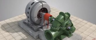
A centrifugal pump, as is clear from its name, is a device that pumps liquid media due to the centrifugal force acting on them. The main working element of this type of pumping equipment, which ensures the formation of such force, is a wheel (or drum), on the outer cylindrical surface of which special blades are fixed.
The pump housing of this type can be made of cast iron or steel alloy. Inside such a housing there is a drive electric motor and a rotation shaft connected to it, on which the wheel with blades is fixed. According to its design, the pump impeller can be open or closed. Open impellers consist of one disk, on the outer surface of which blades are fixed, closed impellers consist of two disks connected to each other by working blades.
Operating principle of a centrifugal pump
The blades are located at a certain angle, their bend is directed in the direction opposite to the direction of rotation of the impeller. This arrangement of blades ensures more efficient operation of pumping equipment. The suction of the pumped liquid medium into the internal chamber of the pump, as well as its expulsion into the pressure line, is carried out through the nozzles.
The principle by which both single-stage devices and multi-stage pumps operate is as follows.
- The liquid, located in the inner part of the pump before it starts, is captured by the blades when the impeller rotates and begins to move with them.
- Under the influence of centrifugal force, the liquid is thrown towards the walls of the inner chamber, due to which high pressure is created near them.
- As it moves through the discharge port area, the high-pressure liquid is pushed into it.
- When the liquid pumped by the pump is thrown towards the walls of the working chamber, a vacuum of air is created in the central part of the latter, which facilitates the suction of the liquid medium through the inlet pipe.
Due to the above-described principle of operation in pumps of both single-stage and multi-stage types, the continuity of the process of suction and expulsion of the pumped liquid is ensured when the impeller rotates. The scope of application of this type of pumping equipment is significantly expanded by the fact that, unlike piston devices, it does not create pulsations of liquid pressure in the pipeline system it serves.
As mentioned above, single-stage and multi-stage centrifugal pumps have design features that determine the differences in their technical characteristics. Thus, the main design elements of a single-stage pump are:
- the body, which is often called the “snail”;
- impeller with blades;
- shaft sealing elements;
- a shaft connected to the drive motor and providing rotation of the impeller;
- chamber sealing elements with oil bath;
- support for bearing assembly;
- load-bearing support;
- hole through which the oil level in the chamber is controlled.
Diagram of a single-stage monoblock pump
A single-stage centrifugal pump, unlike multi-stage models, is equipped with one impeller. A centrifugal multistage pump can be equipped with two or more impellers with blades, which can significantly increase the efficiency of such equipment.
Due to the presence of several impellers, centrifugal multistage devices, when compared with single-stage ones, have certain advantages.
- Using multistage pumps, it is possible to pump liquid with a higher productivity, which characterizes the amount of liquid medium that the hydraulic machine passes through itself per unit of time.
- Multistage pumps are capable of generating a fluid flow with higher pressure levels, measured in meters of water column. In fact, the liquid pressure created by multistage electric pumps is the sum of the pressures created by each of its stages. This quality of multi-stage hydraulic machines makes it possible to achieve higher fluid pressure in the pipeline systems they serve and move it through them over longer distances and greater heights.
Diagram of a multistage sectional pump
A multistage centrifugal pump, depending on its design, can be sectional or spiral. In sectional type devices, during the pumping process, the liquid medium moves sequentially from the first section of the pump to the last, while the liquid pressure also increases sequentially. Modern models of multistage sectional pumps are capable of providing a liquid pumping process performance of up to 900 m3, while the pressure of the working medium created by such devices can reach up to 1900 meters of water column.
CNS pumps: design features, technical characteristics
The decoding of the abbreviation CNS sounds like “Sectional centrifugal pump” . They are used for pumping water (both cold and hot), acids, petroleum products, oils and other aggressive liquids. They have a horizontal configuration, the number of stages is from 2 to 10. They consist of a housing and a rotor. Due to their multi-stage design, they have high performance and create high pressure, which allows this type of pump to be used for industrial purposes. Creating the required pressure directly depends on the number of sections: the more there are, the more pressure can be created using the same amount of liquid.
Pros and cons of equipment
CNS pumps have a number of advantages:
- small dimensions of the devices with powerful pressure;
- the ability to regulate pressure by adding or reducing the number of sections;
- this type of pump is created using high-tech computer modeling, which leads to a reduction in vibration activity and optimization of characteristics;
- almost all models are made of high-strength materials, this makes them resistant to mechanical stress;
- special surfacing increases the anti-corrosion properties of units and increases their productivity.
Meanwhile, the equipment also has certain disadvantages:
- mandatory filling of the device with liquid before starting it;
- complexity of the disassembly and assembly process;
- a large number of parts in the design, which requires high-precision processing on machines in the production of pumping units;
- an incorrect choice of device characteristics leads to its failure (the indicator will be a small pressure of the working environment, noise and vibration exceeding the declared level).
CNS pumps: design and operating principle
The operating principle of a CNS type pump is based on the fact that each section of the unit is connected by a guide device to blowers that connect the output and input of adjacent sections. The liquid is subject to pressure from the section impeller, fed through a guide into the adjacent chamber, where it is again subject to the force of the impeller. So from section to section the pressure increases, in the last chamber the liquid is supplied into the pipeline through the blower hole.
The structure of the central nervous system pump and a description of its parts are presented in detail in the diagram below.
Radial bearings in the brackets serve as a support for the rotor and allow it to move in the axial direction. The shaft at the junction with the body is sealed with cuffs. To prevent water from getting onto the bearings, the design includes fender rings. To reduce pressure on the rotor and suction pipe, the design also provides a hydraulic heel.
According to the design criteria and scope of application, CNS pumps are divided into the following types:
- Standard CNS . Capable of pumping out liquids with temperatures up to 45°C with a minimum content of impurities (less than 0.1%), the diameter of which is no more than 0.1 mm. Can be used both for private purposes and for production. This type includes a whole list of models, among which the most popular are: 05-196, 105-490, CNS 300-240, 500, 63-1400.
- Centrifugal electric pumps with additional marking “G” . Almost identical to the previous view. The difference is that they can be used for hot water and can withstand temperatures up to 105°C. The most popular models of this type are 300-600, CNS 300-360, 60-132.
- Other models marked "G" . Used in turbines and generators. Designed mainly for pumping oily liquids with a temperature of 2-60°C. This range includes units of models CNS 300-600, CNS 300-360, 60-132.
- Models marked with an "H" at the end . Designed exclusively for pumping oil with a temperature of 0-45°C and containing foreign particles with a diameter of no more than 0.2 mm. Includes models such as CNS 105, CNS 105-294, CNS 180-85, CNS 180-255, CNS 300-180.
- Pumps marked “P” . Designed for servicing steam boilers and for increasing pressure in heating systems. Work with liquids over 100°C. Represented by CNS models 60-200, 330-60.
- Pumping units marked “K” . Designed for pumping acidic water with a pH of no more than 6. The temperature of the working fluid is from 1 to 40°C. Models used are 60-66, CNS 60-132, CNS 300-480.
The marking of the unit should be deciphered as follows: the first digital value is productivity (in m3/hour), the second is the maximum hydrostatic head (in meters). Below are more detailed technical specifications of some popular CNS models.
Popular CNS models
CNS 13-70:
- productivity – 13 m3/h;
- hydrostatic head - 70 m;
- power – 11 kW;
- rotation amplitude – 2950 rpm;
- weight – 335 kg.
- productivity – 38 m3/h;
- hydrostatic head - 66 m;
- power – 15 kW;
- rotation amplitude – 2950 rpm;
- weight – 405 kg.
CNS 38-88:
- productivity – 38 m3/h;
- hydrostatic head - 88 m;
- power – 18.5 kW;
- rotation amplitude – 2950 rpm;
- weight – 446 kg.
38-110:
- productivity – 38 m3/h;
- hydrostatic head - 110 m;
- power – 22 kW;
- rotation amplitude – 2950 rpm;
- weight – 491 kg.
180-85
- productivity – 180 m3/h;
- hydrostatic head - 85 m;
- power – 75 kW;
- rotation amplitude – 1475 rpm;
- weight – 1308 kg.
CNS 180-212:
- productivity – 180 m3/h;
- hydrostatic head - 212 m;
- power – 160 kW;
- rotation amplitude – 1475 rpm;
- weight – 1906 kg.
CNS 180-425:
- productivity – 180 m3/h;
- hydrostatic head - 425 m;
- power – 315 kW;
- rotation amplitude – 1475 rpm;
- weight – 3313 kg.
300-120:
- productivity – 300 m3/h;
- hydrostatic head - 120 m;
- power – 200 kW;
- rotation amplitude – 1475 rpm;
- weight – 2600 kg.
CNS 300-300:
- productivity – 300 m3/h;
- hydrostatic head - 300 m;
- power – 400 kW;
- rotation amplitude – 1475 rpm;
- weight – 3907 kg.
Rules for operating the central nervous system pump
Proper operation of the central nervous system pump will significantly extend its service life and help avoid repairs.
Before starting the pump, do the following:
- manually turn the rotor (it should rotate easily);
- the direction of rotation of the engine when the clutch is disconnected should be clockwise;
- check the integrity of the product, the reliability of all components and fastenings;
- check the bearings and their lubrication level, the condition of the seals, and also make sure that the couplings are securely fastened;
- check the presence and serviceability of grounding;
- Fill the pump with liquid and bleed the air through the drain.
In winter, after a long period of inactivity, manufacturers recommend warming up the pump piping with hot water or steam. You need to start the equipment with the discharge valve closed, gradually opening it to the desired level of water supply and pressure.
After starting, check the blower valve again - operating with the valve closed for more than 5 minutes will lead to equipment breakdown. It is also prohibited to suddenly open the valve completely and completely, or start the pump without test filling the liquid.
Central nervous system pump: device, characteristics, repair.
Content
Centrifugal pump CNS is used in various fields of industrial production, so it has gained wide popularity in the industrial sector.
Pumps of the CNS type (interpretation: C - centrifugal, N - pump, S - sectional) are designed for pumping water from mines in the coal and mining industries. The use of central nervous system pumps in high-pressure fire extinguishing systems, for supplying water to high-rise buildings, for powering steam boilers, in the construction industry, and in transport has become widespread. Quite often, a central pump is used as a chemical unit for transporting oil and petroleum products.
CNS pump design
The operation of the central nervous system pump is to create excess pressure and push the pumped medium into the discharge pipeline. The mechanical energy of the engine is transferred to the flow of the pumped liquid by impellers mounted on one shaft in one sectional housing.
During rotation, each blade of the impeller interacts with the liquid that is located directly inside the section. Because of this, each section acquires centrifugal acceleration. At the same time, a zone of excess pressure appears at the periphery of each section. The pressure of a CNS type pump is equal to the sum of the pressures created by each installed impeller.
The body of a sectional type central nervous system pump consists of separate sections, the number of which is equal to the number of stages minus one, since one wheel is located in the front cover.
The seal between the sections is ensured by rubber gaskets. The sectional design of the pump casing allows you to increase or decrease the number of sections and thereby increase or decrease the pressure without changing the flow.
The pump covers are cast in one piece with both suction (rear cover) and discharge (front cover, farthest from the engine) pipes. The seal of the suction section has a hydraulic seal, to which water is supplied through a tube made in the rear cover of the pump housing.
A multistage pump of the CNS type is available with a number of impellers from 2 to 10. The pumped liquid is transferred from one impeller to the next through the internal channel and blades of the guide vane. The guide vanes and impellers are sealed using sealing rings.
All sections are connected to each other using guide vanes. These elements are made in such a way that liquid cannot get outside. At the same time, the pumped liquid, which receives additional pressure from the wheel of the very first section, must flow from the first section to the second. It is also exposed to the wheel blades. As a result, the pressure of the fluid increases as it flows from one section to another.
Due to the fact that a large number of impellers with an axial water inlet are installed in sectional pumps, large hydraulic axial forces arise, the unloading of which is carried out using automatic unloading devices in the form of balancing disks (hydraulic heel). Some CNS type pumps are produced with two impellers with axial input of left and right rotation.
The axial forces are balanced by the symmetrical arrangement of the wheels. Spiral diffuser outlets are made in a common casting of the body.
Such an unusual pump design allows for high efficiency, which is why this equipment is enviably popular in a variety of industries. After the liquid has passed through all sections, it will go into the discharge pipeline, where it will remain.
The design of the central pump allows it to be used for almost any task. For this reason, pumps are often used to improve the efficiency of an industrial plant. They can often be seen in various factories, where they act as pressure pumps in much larger units.
On the Russian market, these pumps are produced by Russian companies, so it is quite natural that their cost is quite low.
Characteristics of the central pump
CNS – centrifugal electric pump. An impeller (multistage) is used as the main working body.
Multistage pumps designed for pumping clean water with temperatures up to 105 degrees Celsius are usually divided into normal and high-speed.
Normal CNS pumps show technical characteristics for flow in the range of 8 - 850 m 3 / hour, pressure from 40 to 1440 meters and efficiency of 67-77%.
High-speed ones show a flow of 38-1000 m 3 / h at a head of 136 - 2000 meters, they are installed with a headwater of 2-6 m, efficiency is in the region of 72-80%.
The characteristics of the CNS pump allow it to pump almost any liquid. It can be either water or oil. To improve operating efficiency, this device is driven by an electric motor. It's quite powerful.
Each wheel of this complex device is connected in series. For this reason, these units are mounted directly on 1 shaft made of steel. With the help of an electric motor, the wheels are also turned on, so it is quite natural that such pumps are often used to pump oil. It is difficult to find another tool that could be used for similar tasks.
Sectional pump TsNS
Tsns sectional pumps have a special design. The motor is installed as a separate unit. This is the most suitable option to significantly increase the efficiency of the equipment. During the manufacture of a sectional pump, manufacturing companies use cast iron, as well as steel grades 35L and 40X.
Directly during the operating mode of this device, you can change the pressure. For this reason, it is possible to adjust the length of the shaft, as well as set the tie rods to a specific size. The rotor, which is located inside the chamber, is driven by bearings.
You can purchase options with both water and oil bearing cooling. Some models use several types of temperature control at once. This is the best option for the CNS sectional pump to work in any conditions.
The advantages of sectional pumps are the ability to change the pressure by adding or reducing the number of sections and the small dimensions of the pump at high pressures.
The disadvantages are the difficulty of disassembling and assembling the pumps, low efficiency and a large number of parts that require high precision processing on metalworking machines.
Popular models
The TsNS 180 pump is a multistage centrifugal pump. It is used for pumping neutral liquid (process water) and any other liquids that are not explosive. Solid inclusions in liquids should not be more than 0.1%. Particle size – no more than 0.25 mm.
The TsNS 300 pump belongs to the sectional centrifugal pumps. It is used to pump liquid whose temperature is less than 45 degrees Celsius. The pumped liquid must not contain any mechanical impurities. The size of particles that may be present in the liquid should not exceed 0.1 mm.
TsNS 60 pumps are also used for pumping water, which boasts a normal pH value (7-8.5) and a temperature of no more than 45 degrees Celsius. This pump can be seen in the mines.
TsNS 105 pump is used for pumping liquids whose temperature does not reach 45 degrees Celsius. This pump can only be produced in the UHL climatic version. You should also pay attention to the mass of mechanical impurities. It should be no more than 0.1%.
All of the listed sectional horizontal pumps differ from each other in their level of performance. As the name of each device implies, they are designed to pump liquid.
Each of the listed pumps (pump TsNS 180, pump TsNS 300, pump TsNS 60, pump TsNS 105) allows you to perform similar tasks, but their performance imposes certain limitations. Before purchasing, it is advisable to consult with the seller and clarify the functionality of the pump.
Repair of central nervous system pumps
Repairing central nervous system pumps, like all complex technical devices, is a difficult task even for the most trained users. It is not surprising that professional craftsmen are hired for this. If this is not possible, then you will have to study the provided repair instructions as carefully as possible. It is of interest to anyone who would like to repair the pump as soon as possible. To do this you will have to use a lot of tools and show remarkable ingenuity.
All recommendations presented must be followed strictly. This will be quite enough to carry out the repairs yourself. In this case, the operation of the central nervous system pump will not raise any questions.
Helpful tips for repairs: Before disassembling the pump, you need to remember the exact location of each part. This is very important, because otherwise it will not be possible to assemble the device. Complex (technically) repair work must be performed after 26 thousand hours of operation. In this case, it is necessary to replace the working shaft, as well as the wheel, housing seal rings, and pressure bushings. Then the operation of the central nervous system pump will be uninterrupted for a long time. When operating the equipment, you must follow all the manufacturer’s recommendations set out in the instructions.
Equipment design and operating principle
The multistage central nervous system has a body consisting of separate sequential sections (there are from 2 to 10 of them). In this case, the number of impellers always exceeds the number of sections by one. This is due to the fact that one impeller is located in the front cover of the equipment. Due to this design of the unit, it is possible to increase or decrease the pump pressure at the same flow rate.
All wheels of the device are connected to each other and mounted on a common steel shaft; it moves due to an electric motor (installed as a separate unit). The gap between the walls of the working chamber and the steel shaft is protected by an stuffing box seal; some models are equipped with a mechanical seal. The device body contains front and rear holders, covers with lubricant for discharge and suction systems, and a cooling cavity for bearings.
Certain materials are used in the manufacture of CNS. This is SCh20 cast iron and steel varieties - 35L and 40X.
For stable, long-term operation, the devices are fed with a backwater of 2–6 meters. Without this, pumps will quickly collapse due to the cavitation effect. When the temperature of the working fluid increases above 45 ºС, it is necessary to increase the pressure proportionally.
The operating principle of the central nervous system apparatus corresponds to the operating principle of any centrifugal unit. The disc blades rotate the liquid, pushing it towards the outlet. In this case, the vacated cavity is filled with the next portion of the working medium. After passing through the first section, the water enters the second, etc. There it is similarly affected by the wheel blades. As a result, the pressure of the liquid increases as it moves through the sections of the apparatus, after which it enters the discharge pipeline.
The general operating characteristics of the CNS are as follows:
- the total pressure of the equipment is the sum of the pressures created by all the impellers (in general, within 2300 m);
- liquid supply is carried out in the range of 30–1000 m³/h;
- Efficiency reaches 83%;
- the maximum pressure created in the housing is 270 kgf/cm2.
Equipment
Centrifugal pumps CNS are equipped with:
- Reverse-acting foot valve with protective mesh. The functional element serves to retain liquid while preparing the pump for startup. The presence of a mesh helps retain abrasive particles contained in the working environment.
- Vacuum gauge - makes it possible to measure the vacuum in the suction pipe of the pump. Most often, this component is located on the pipeline in the area of the valve and body.
- A pressure gauge is an element of a pressure pipe that is used to measure pressure and pressure parameters in the system.
- Safety valve - located behind the valve on the discharge pipe. Provides protection for the pipeline and pump housing from so-called water hammer.
CNS - used for transporting composition-neutral water with an impurity content at a level that does not exceed 0.2%. Suitable for working with liquids with temperatures from 1 o C to 45 o C. In order for devices of this category to be successfully used in a water supply system, the size of solid particles in the pumped medium should not exceed 0.2 mm.
TsNSg – pumps for pumping hot water with a neutral composition at a temperature from 45 o C to 105 o C. A special designation in the definition of the equipment class in the form of the index “g” indicates work with hot liquids. For effective operation of such pumps, mechanical impurities in the working medium should occupy only 0.1%, and the size of solid particles should be no more than 0.1 mm.
TsNSk – units for working with acidic waters. The pH of the pumped liquids should be no more than 6.5. Such pumps are used to supply water with a temperature that does not exceed 50 o C.
TsNSn – systems for transporting petroleum products of a certain density. For effective operation, it is necessary to maintain the operating pressure at a level of no more than 500 mmHg. Art.
TsNSm is a category of oil pumps that are used to maintain the uninterrupted operation of large industrial units, to lubricate bearings and seals in turbogenerators.
Popular models of pumping equipment:
- CNS 180
. This unit has a multi-stage design. It is used when it is necessary to organize the transportation of neutral liquids and other working media that cannot be classified as fire hazardous. The transported medium must not contain more than 0.1% solid inclusions, and the particle size must be up to 0.25 millimeters. - CNS 300
. This option applies to sectional pumping equipment. The units are used when it is necessary to pump liquids whose temperature is less than +45 degrees Celsius. The working environment should not contain large mechanical inclusions; the permissible particle size is less than 0.1 millimeters.
- CNS 60
. Such equipment is used when it is necessary to organize the transportation of liquids with normal hydrogen values - ranging from 7 to 8.5. The working environment temperature should be less than +45 degrees. These pumps are often installed in mines.
- CNS 105
. Such pumping equipment has a special climatic version UHL. The temperature of the transported working medium should be no more than +45 degrees Celsius, and the amount of mechanical impurities should be less than 0.1%.
The main distinguishing feature of all the CNS pumps presented above is the level of performance. offers to purchase equipment of various types, all products comply with Russian and international quality standards.
Before purchasing one or another version of a centrifugal pump, you must consult with specialists. Our employees will answer all the client’s questions and give comprehensive recommendations for choosing a product with optimal technical properties.
Installation
The installation of a sectional centrifugal pump is carried out in accordance with the requirements specified by the manufacturer. The equipment is connected to the pipeline via a valve and check valve. The latter prevents damage to the system when water hammer occurs, which is a consequence of the reverse movement of fluid as a result of a sudden loss of power to the system.
As for the installation of pipelines, they are installed on separate supports in such a way that vibrations arising under the force of the liquid are not transmitted to the pumping equipment.
If the centrifugal pumping system is mounted at a level below the transported working medium, the unit is equipped with a pressure gauge, which is placed in front of the valve on the pipeline. Otherwise, install a vacuum gauge.
The central nervous system pumps are started only when the valve is closed, which subsequently opens independently when the engine reaches the required number of revolutions. It is extremely undesirable to allow the unit’s electric motor to operate with the valve closed for more than 5 minutes.
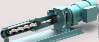
Design and principle of operation of central nervous system pumps
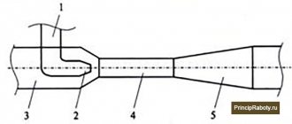
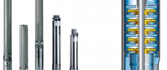
Centrifugal pumps CNS (Fig. 1) – horizontal, sectional, manufactured with a number of stages from two to ten.
The pump consists of a housing and a rotor.
The suction 21 and discharge 11 covers are attached to the body, as well as the guide vane housings 17 with guide vanes 18, rear 3 and front 35 brackets. The bodies of the guide vanes and the suction and discharge covers are tightened with tie rods and nuts. The joints of the guide vane bodies are sealed with a medium-hard rubber cord.
The pump rotor consists of a shaft 36, on which a spacer sleeve 30, a shaft jacket 26, impellers 13 and 16, a spacer sleeve 10, adjusting rings and a hydraulic heel disk 37 are installed. All these parts are tightened on the shaft with a shaft nut 6.
The places where the shaft exits the housing are sealed with multilayer weave packing. The packing rings are installed with a relative displacement of the cuts at 120 0 C
.
The stuffing box packings are pressed by the stuffing box bushings.
The rotor supports are two radial bearings, which are installed in brackets with a fit that allows the rotor to move in the axial direction by the amount of the rotor “run-up”. The places where the shaft exits the bearing housings are sealed with cuffs.
To prevent water from entering the bearing chambers, fender rings are installed.
The O-ring guide vane housing, the O-ring guide vane and the impeller together form the pump stage.
The operation of the pump is based on the interaction of the rotating impeller blades and the pumped liquid.
The impeller, rotating, imparts movement to the fluid located between the blades. Due to the resulting centrifugal force, the liquid from the center of the wheel moves to the outlet, and the vacated space is again filled with liquid coming from the suction pipeline under the influence of atmospheric or excess pressure.
From the impeller, the liquid enters the channels of the guide vane and then into the second impeller with the pressure created in the first stage. Next, the liquid enters the third impeller with increased pressure created by the second stage, etc.
From the last impeller, the liquid passes through the guide vane into the discharge cover, from where it enters the discharge pipeline.
Due to the fact that the pump casing consists of separate stages, it is possible, without changing the flow, to change the pressure by installing the required number of pump sections. In this case, only the length of the shaft, tie rods and water supply system tube changes.
During operation of the pump, due to the pressure of the liquid on the unequal area of the lateral surfaces of the impellers, an axial force arises, which tends to displace the pump rotor towards the suction side. To balance the axial force in the pump, a hydraulic heel is used, consisting of a hydraulic heel disk 37, a hydraulic heel ring 8, a relief bushing 9 and a spacer bushing 10.
The liquid, passing through the annular gap between the unloading bushings and the spacer bushing into the unloading cavity B ,
presses on the hydraulic heel disk, as a result of which the rotor moves towards the discharge cover and a gap is formed between the working surfaces of the hydraulic heel disk, through which the liquid passes into the cavity of the
bracket
G. The size of the resulting gap depends on the pressure in the unloading cavity and is set automatically.
From cavity D, the liquid partially passes through the stuffing box, cooling the shaft nut, and the main part of the liquid through the bypass system enters cavity D of the hydraulic seal, preventing air from leaking through the seal.
From cavity D, part of the liquid passes out between the shaft jacket and the stuffing box, and the rest is discharged through the nipple into the drain. When the pump operates with an inlet pressure of up to 0.3 MPa
, the liquid flowing from the drain pipe can be directed into the suction pipe.
The pressure in the water seal cavity is slightly higher than atmospheric pressure (up to 0.3 MPa
), which prevents air from being sucked into the pump through the stuffing box.
It is necessary that the pumped liquid can always seep out between the shaft jacket and the stuffing box. Excessive tightening of the oil seal accelerates wear of the shaft jacket and increases friction losses.
The pump rotor is driven into rotation by an electric motor through an elastic sleeve-pin coupling, consisting of two coupling halves, which are connected to each other through rubber bushings mounted on cylindrical steel fingers, rigidly fixed in the coupling half of the electric motor. The direction of rotation of the pump rotor is right (clockwise) when viewed from the electric motor.
Start the pump.
Before starting the pump, do the following:
· check the rotor rotation by hand (the rotor should rotate easily without jamming);
· check the direction of rotation of the electric motor with the coupling disconnected (the direction of rotation should be clockwise when viewed from the side of the electric motor);
· remove all foreign objects from the pump, check for damage to pump parts, and for loose bolts in the pump trim;
· check the presence and quality of oil in the bearings, the serviceability of the lubrication system, and also lubricate the moving parts at their connections;
· check the installation of guards on the clutch couplings and their fastening;
· check the condition of the oil seals, whether the gearbox is skewed and whether the oil seals are sufficiently stuffed and tightened;
· check the rotor moves towards the suction side according to the mark (Fig. 2), check the position of the mark with the rotor moved all the way towards the suction side. The mark must be flush with the end plane of the front cover 1 of the front bracket. The rotor offset should be no more than 3 mm
;
· check the presence and serviceability of pressure gauges on the pump discharge and receiving pipeline;
· make sure that the pump and electric motor are grounded;
· using a special key, close the valve on the discharge pipeline and open it on the receiving pipeline (if the valve control is automatic, closing and opening the shut-off valves must be done by pressing the “start” and “stop” buttons on the control panel);
· fill the pump with the product, bleed the air from the pump through the drain line.
In winter, when the pumps are stopped for long periods, it is necessary to put them into operation after heating the piping with steam or hot water and test pumping the liquid through the pipes. It is prohibited to heat the pump piping with an open source of fire.
The pump must be started only with the discharge valve closed. Before starting, make sure that the pump inlet pressure corresponds to the operating parameters. The pump is started by pressing the “Start” button on the pump control panel.
After starting the pump, once it has reached its full speed, it is necessary to gradually open the shut-off valve on the pressure pipeline and achieve the required flow and pressure by adjusting the degree of opening of the valve.
· work with the valve closed for more than 5 minutes, as this leads to significant heating of the liquid in the pump;
· open the valve on the discharge line quickly and completely, as this can lead to disruption of the liquid supply;
· put the pump into operation without first filling it with product, even for a very short time;
· adjust the pump performance and pressure using valves on the receiving pipeline.
After starting, you should additionally listen and inspect the pump to see if there are constant knocking noises.
If all parameters of the pump correspond to the operating parameters, it is left in operation, and there must be a sign on it: “Unit in operation.”
Design
A centrifugal pump is a device that is capable of converting mechanical energy into kinetic energy. With its help, you can pump the working medium from one point to another, while creating pressure and pressure. It is worth noting that the final results depend on the performance of the equipment.
The unit consists of 2 main elements, these are:
- Disc with blades
. In another way it is called an impeller; there can be several of them.
- Spiral housing
. It is presented in the form of a curved pipe. The working medium is pumped through its internal part.
Centrifugal pumps can differ in the following design elements:
- Type of impeller with blades.
- Type of installed bearings.
- The location of the body.
- Motor mounting type.
- Number of steps
.
Centrifugal pump housing
In most situations it is made of cast iron, but there are models made of bronze or stainless steel. In the latter case, the equipment is used in the food and chemical industries. The body is shaped like a spiral, something like a snail shell. Its flow area gradually increases as it approaches the outlet.
A kind of wedge is installed near the outlet pipe; it is also called a water cutter. The presence of such a device ensures that during operation of the pump the working medium will not circulate in a spiral, but will begin to flow into the outlet pipe.
A gradual increase in the flow area of the cochlea is important, since this creates pressure in the system.
Features of impellers
Manufacturers offer equipment with three types of impellers:
- Open.
- Half-closed.
- Closed.
The first type of product has a simple design. Only sharp curved blades are provided here, which are located on a metal sleeve.
Using open impellers, you can transport almost any type of working media that may contain solid impurities. This may be water containing sand, dirt, dust and other solid particles. These types of pumps can transport viscous liquids.
Equipment with open impellers is used in treatment plants and factories that pump wastewater containing large amounts of impurities. The sharp blades are capable of cutting through large particles to ensure high throughput and smooth transport of liquids.
When the blades are mounted on the back of the plate, such devices are called semi-closed wheels.
If they are between 2 plates, then these are closed wheels. This type of product is highly effective. In this case, the liquid will be pumped along a strictly planned path. As a result, more water will flow to the outlet pipe and less will remain in the system. The disadvantages of such devices include the fact that they can quickly become clogged with dirt and debris.
Some people may say that curved blades are needed to push the work media better, but this is a false statement. Curved blades allow water to move along the smoothest path possible. Elements of the wheel with blades, twisted backwards, make it possible to stabilize the conditions of movement of the working environment at high speed and reduce the load on the electric motor.
The wheel with blades rotates counterclockwise. The direction can be determined by the shape of the bends of the blades.
Shaft and bearings
Each centrifugal pump is equipped with a shaft on which impellers are fixed. So that it does not vibrate, works symmetrically, and does not deviate from the axis, the product is fixed in the housing using bearings. There are 2 ways to install it:
- Console.
- Symmetrical.
Cantilever mounting method
Here the wheel with blades will be installed at one end of the shaft, and the bearings will be installed at the opposite end. The suction and outlet openings are located perpendicular to each other. In this case, the first is located directly in the center of the wheel with blades.
In another way, a unit with this design is called pumps with an end suction method. The units have gained great popularity due to their simple design, maintainability and affordable cost. The disadvantages of the design include the complex path of movement of the pumped working medium.
During operation of the unit, a low pressure zone is created in the suction pipe. Where the wheel moves, a zone with high pressure levels is formed. The liquid, having received kinetic energy, is pumped into the spiral casing.
During operation of the equipment, water flows to the back plate of the impeller. This upsets the pressure balance, which leads to heavy load on the unit. The installation of reinforced bearings will help compensate for the pressure balance. You can also drill holes in the wheel plates. This will equalize the pressure, but this method is also not as effective.
Symmetrical mounting
This is the most reliable way to attach the shaft. In this case, the bearings are located on both sides, symmetrically to each other. This design significantly improves shaft support. Also, symmetrically arranged bearings allow the use of closed wheels with double suction.
During equipment operation, zones with low and high pressure are created. Thanks to the symmetrical design, it is possible to eliminate the load on the impellers and achieve a pressure balance.
This type of pumping equipment also has another advantage. The suction and outlet openings of the devices are located parallel to each other, and the body itself is divided into axes.
Pumping equipment is easy to repair. In order for the technician to get to the inside of the equipment, it is enough to unscrew the bolts and remove the special cover. In this case, there will be no need to remove the main part of the unit from the system. In another way, this type of centrifugal pumps is called products with a collapsible casing.
As you can see, the device with symmetrical bearings is easy to maintain and repair. That is why it is perfect for your well. However, this type of equipment also has its drawbacks. Pumps with a symmetrical design are more expensive than units with an end method of supplying the working medium. In addition, it is subject to more stringent maintenance conditions; it is necessary to constantly monitor the condition of the sealing elements.
Shaft location
offers to purchase equipment in vertical or horizontal versions. With the same power, the shaft arrangement does not affect performance in any way. Thus, vertical devices are convenient to install in places with limited space. These units are often used in the construction of autonomous water supply in wells and wells.
Types, design and features of central nervous system pumps
The CNS pump is a centrifugal sectional electric pump unit of horizontal design. CNS pumps are used to transport purified liquids, the permissible amount of mechanical impurities is no more than 0.2% with solid inclusions measuring only 0.2 mm. Pumps of this type differ from others in their multi-stage sectional design. Today, vertical pumps of a similar type are also in great demand, but we will talk about them a little later.
Design features of central nervous system pumps
The pump consists of a rear and front holder, a discharge and suction pipe and guide vanes, which are secured with special fasteners. For sealing between sections, rings made of a certain material that is resistant to the pumped medium are used. The internal design of CNS pumps is also quite simple. On a shaft that rotates through electric work. The impeller, bushing and bearing are attached to the engine.
Centrifugal sectional pumps
are equipped with:
- A vacuum gauge to measure the vacuum at the pump inlet.
- An inlet valve to delay the pumped medium before starting the unit and a mesh that retains mechanical impurities.
- A pressure gauge, which is used to measure outlet pressure.
- A safety valve that serves as protection against water hammer.
The design and equipment may vary slightly depending on the pump manufacturer. Depending on the purpose of the unit, there are several types of sectional pumps:
CNS pumps are used for pumping neutral liquids with temperatures up to 45°C. The inclusion of mechanical impurities does not exceed the norm of 0.2% with a size of no more than 0.2 mm. Pumps are most often used for water supply.
TsNSg pumps are also designed for pumping chemically neutral liquids; they are often used for pumping hot water. Permissible temperature range from 45 to 100°C.
TsNSk pumps are used for pumping acidic waters, chemical liquids, and sometimes even for pumping food liquids. All pump elements are made of stainless steel. Pumps produced by Tekhmash are capable of pumping liquid with temperatures up to 150°C, and when installing a tank with barrier liquid, they can withstand temperatures up to 240°C.
TsNSn – pumps for pumping petroleum products.
TsNSm – pumps for pumping oil and other liquids of similar consistency.
Technical characteristics of centrifugal sectional pumps:
- The productivity of central nervous system pumps is from 1 to 500 m3/h.
- Pressure – from 10 to 600m.
- Electric power engine - from 1.1 to 800 kW.
In various fields of industry and when equipping domestic water supply systems, the use of centrifugal pumps is very common. This equipment makes it possible to pump out liquids from wells and wells and transport them through pipelines over a considerable distance.
Types of multistage pumps - classification of market models
Modern multistage pumping equipment is divided into the following types:
- Vertical units - pumps of this type are installed in a vertical position. Among the advantages of a vertical unit, one should highlight the generation of very high liquid pressure, the ability to pump liquid at a temperature of 100 °C and long service life without failures;
- Horizontal multistage pumps are the optimal equipment for arranging water supply in a country house. The working planes of such a pump are performed in a horizontal position. This makes it possible to obtain water under high pressure with low device productivity.
Depending on the areas of application, the following units are distinguished on the market:
- Industrial high-pressure pumps – have larger dimensions and higher power. Each industrial pump has a special coating that protects it from chemicals;
- Household devices - these units have smaller dimensions and light weight. They are much easier to maintain and repair, they consume less electricity and make less noise. At the same time, they do not produce as high a pressure as equipment of the first type.
When buying a multi-stage unit, you must remember that industrial devices are characterized by fairly high electricity consumption. Because of this, it is better not to buy them even for servicing large farms. Instead, you can purchase two household pumps, which in total will consume much less energy than is required to operate one industrial unit.
Design features of a centrifugal pump
If you look at the equipment in cross-section, you can identify the main structural elements:
An electric motor that acts as a drive.
A shaft that transmits rotation from the engine to the operating pulley.
A pulley with blades that move liquid inside the working chamber.
Bearing unit ensuring easy rotation of the shaft and wheel.
Seals that protect the structure from the negative effects of liquid media.
The snail-shaped body is equipped with two pipes.
Device
Units of this type consist of the following structural elements:
- body made of materials with high anti-corrosion properties;
- suction pipe through which liquid is supplied to the pump;
- a discharge pipe through which water is supplied under pressure directly into the system;
- impellers;
- main shaft;
- bearings that have self-lubricating property;
- mechanical seals that prevent water from entering outside the working chamber.