Universal boring turning tools
Boring turning tools are used for machining holes and internal surfaces. These cutters are divided into two types:
1. For processing blind holes , the cutting plate of such cutters has a triangular shape, and the working part is made with a bend.
Universal turning boring tool for blind holes.
2. For processing through holes , the working part of these cutters also has a bend, and this cutter is used for boring pre-drilled holes or for boring holes in pipes.
Universal turning boring tool for through holes.
The maximum machining depth of the holes of these cutters depends on the size of the holder.
Types of incisors
Boring cutters are divided into several subgroups, depending on the main parameters. Feed on the machine can have several directions. Considering this fact, the incisors can be: left; right.
For each type of hole, the required design of the equipment . The accuracy of processing and operation time depend on this. Depending on its design, the tool is divided into several types:
- Direct. The axis of the holder coincides with the line of the cutting head. Sometimes the parallelism of the axes is maintained.
- Bent back. The axis of the tool head can deviate in a certain direction from the axis of the holder.
- Curved. The holder has a curved axis.
- Retracted. The holder is wider than the tool head.
It must be said that sometimes such forms are not enough. Especially when the part has a complex shape. Especially for such cases, designers are developing unique types of boring tools .
The shape of the holder divides the cutters into several types:
- Round.
- Rectangular.
- Square.
The classification of a tool is also influenced by the manufacturing method. The equipment is divided into groups:
- Solid. The tool is made of a homogeneous material.
- Composite. A carbide plate is used to make the cutting part. It can be fixed to the holder with a regular bolt or soldered.
Modern boring turning tools
Modern boring lathes have quite a variety of designs, and they are primarily used on CNC lathes.
These cutters include various small-sized inserts for processing small diameters.
Small turning inserts.
And standard turning boring bars with replaceable inserts.
Turning boring bars for CNC machines.
When machining with these mandrels, one mandrel is usually used for finishing and another for roughing .
Boring turning tool with replaceable insert for roughing.
Boring turning tool with replaceable insert for finishing.
These cutters are designated: A32T-SVUBR 16 and A25T-SDUCR 11 .
Next, download the 3D models of these cutters and open them in SolidWorks.
Fastening the cutting elements of the cutter
The machine has a special tool holder. Several different cutters can be mounted in it at the same time. The cutter is fixed with special bolts. The tool must be positioned parallel to the centering axis of the machine. The cutting head of the tool must face the spindle.
The turner, installing the cutter, sets its tip . It must coincide with the center axis of the machine (slightly above the center is allowed). If you set the tip below the centerline, the back of the tool will hit the workpiece.
To control accuracy, the cutter is brought directly to the top of any headstock. Adjustment is carried out using pads of different thicknesses . And there should only be two of them. Otherwise, the tool will begin to vibrate.
The protrusion of the cutter from the tool holder should be minimal . If the overhang is too large, the strength of the cutter will become much less. Vibration may occur during boring. The mounting of the cutter must be very reliable. Definitely two bolts.
Where to get 3D models of boring tools for SolidWorks
You can, of course, build them from scratch, but there is no point in this when you can simply go to the website and download the model data.
Search on the Sandvik coromant website
To download cutter models, enter the designation of the holders in the search bar at the top of the site, go to the page for this tool and click on the download page.
Download the 3D model of a turning boring cutter A32T-SVUBR 16 for SolidWorks.
Then open this boring cutter in SolidWorks.
Cutter A32T-SVUBR 16 in SolidWorks
After which we do the same for the A25T-SDUCR 11 and open it in SolidWorks.
Cutter A25T-SDUCR 11 in SolidWorks
A25T-SDUCR 11 boring tool will be used as roughing tool and A32T-SVUBR 16 will be used as finishing tool. This can be seen further in the turning animation.
Boring cutters and their installation
Boring tools
The holes are bored on lathes using boring cutters (Fig. 118). Depending on the type of hole being bored, they are distinguished: boring cutters for through holes (Fig. 118, a) and boring cutters for blind holes (Fig. 118, b). These cutters differ from each other in the main angle f. When boring through holes (Fig. 118, a), the main plan angle is φ = 60°. If a blind hole with a shoulder of 90° is bored, then the main angle φ = 90° (Fig. 118, b) and the cutter operates as a thrust cutter or φ = 95° (Fig. 118, c) - the cutter operates with longitudinal feed as a thrust feed, and then with a transverse feed as a scoring feed.
Boring cutter sharpening angles
In Fig. 118 shows the sharpening angles of boring cutters, which are chosen basically the same as for cutters for external turning, with the exception of the clearance angle a, which for boring cutters usually has an increased value. The size of the clearance angle depends on the diameter of the hole being bored: the smaller the diameter of the hole, the larger the clearance angle of the cutter should be.
Rice. 118. Boring cutters equipped with hard alloy plates: a - through-boring for processing through holes, b and c - persistent-through for processing blind holes
Complexity of the operation
Boring is a more complex operation than external turning of surfaces, since:
- when boring, the cross-sectional size of the cutter should be significantly smaller than the diameter of the hole, and the projection of the cutter from the cutting head is slightly greater than the length of the hole being bored (Fig. 119), therefore, when boring a hole of significant length, bending of the cutter is possible, and at high cutting speeds - strong vibrations. Consequently, such cutters do not make it possible to cut chips of large cross-section;
- When boring, it is less convenient to observe the work of the cutter, since cutting occurs inside the hole.
Rice. 119. Boring a hole with a cutter
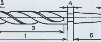
For boring holes with a diameter of up to 70 mm, the innovative turner V.K. Seminsky proposed a special boring cutter equipped with a hard alloy plate (Fig. 120). The cutter shaft has a square cross-section along its entire length, the working part of the cutter is rotated by twisting during manufacturing at an angle of 45° relative to the supporting part. This cutter is characterized by increased rigidity compared to a conventional boring cutter and allows an increase in the chip cross-section by 4-5 times. When working with such a cutter at an increased cutting speed, no vibrations are observed even with a significant overhang of the holder.
Rice. 120. Boring cutter, equipped with a carbide plate, designed by V.K. Seminsky
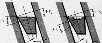
To increase the vibration resistance of the cutter, the innovative turner V. Lacour proposed a new design of a boring cutter with a carbide plate (Fig. 121). The peculiarity of these cutters is that their main cutting edge is located at the level of the neutral axis of the rod. This arrangement of the cutting
Rice. 121. Boring cutter designed by V. Lakura
edge provides the cutters with a significant increase in vibration resistance and, as a result, makes it possible to work at high cutting speeds and achieve improved cleanliness of the machined surface.
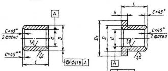
Rice. 122. Mandrel with a cutter for boring a through hole
Installation of cutter
Long holes are bored with cutters fixed in special massive mandrels, the dimensions of which depend on the diameter of the hole and its length. Replacing a solid boring bar with a small cutter inserted into a boring bar provides significant savings in expensive tool material. The method of attaching the cutter to the mandrel depends on its purpose. In Fig. 122 shows a mandrel for boring a through hole; here the cutter is located at a considerable distance from the end of the mandrel. To bore blind holes, the cutter is attached in such a way that it protrudes slightly beyond the front end of the mandrel.
Before boring the hole, it is necessary to set the cutter to the required diameter along the dial of the cross-feed screw, and then bore the hole by hand to a length of 2-3 mm. After measuring the diameter with a caliper or other measuring device and making sure that the size is correct, bore the hole to the remaining length. It is especially important to correctly set the cutter to the required diameter when finishing boring.
The position of the cutting edge of the cutter depends on the type of boring. When rough boring, it is recommended to set the cutting edge at the height of the centers or slightly lower. When finishing boring, the cutting edge must be positioned above the center line by approximately 1/100 of the hole diameter, taking into account that due to the force arising from the resistance of the cut chips, the cutter can be pressed down.