GOST 14098-2014
INTERSTATE STANDARD
WELDED CONNECTIONS OF REINFORCEMENTS AND EMBODIED PRODUCTS OF REINFORCED CONCRETE STRUCTURES
Types, designs and sizes
Welded joints of reinforcement and inserts for reinforced concrete structures. Types, constructions and dimensions
MKS 91.080.40
Date of introduction 2015-07-01
Preface
The goals, basic principles and basic procedure for work on interstate standardization are established by GOST 1.0-92 “Interstate standardization system. Basic provisions" and GOST 1.2-2009 "Interstate standardization system. Interstate standards, rules and recommendations for interstate standardization. The procedure for development and adoption, application, updating and information research center "Construction"
2 INTRODUCED by the Technical Committee for Standardization TC 465 “Construction”
3 ADOPTED by the Interstate Council for Standardization, Metrology and Certification (Minutes dated September 30, 2014 70-P)
The following voted for the adoption of the standard:
| Short name of the country according to MK (ISO 3166) 004-97 | Country code according to MK (ISO 3166) 004-97 | Abbreviated name of the national standardization body |
| Azerbaijan | AZ | Azstandard |
| Armenia | A.M. | Ministry of Economy of the Republic of Armenia |
| Belarus | BY | State Standard of the Republic of Belarus |
| Kyrgyzstan | KG | Kyrgyzstandard |
| Russia | RU | Rosstandart |
(Amendment. IUS No. 1-2022).
4 By Order of the Federal Agency for Technical Regulation and Metrology dated October 22, 2014 N 1374-st, the interstate standard GOST 14098-2014 was put into effect as a national standard of the Russian Federation on July 1, 2015.
5 INSTEAD GOST 14098-91
Information about changes to this standard is published in the annual information index “National Standards”, and the text of changes and amendments is published in the monthly information index “National Standards”. In case of revision (replacement) or cancellation of this standard, the corresponding notice will be published in the monthly information index “National Standards”. Relevant information, notifications and texts are also posted in the public information system - on the official website of the Federal Agency for Technical Regulation and Metrology on the Internet
AMENDED Change No. 1, approved and put into effect by order of the Federal Agency for Technical Regulation and Metrology dated 04/18/2019 N 142-st from 09/01/2019
Change No. 1 was made by the database manufacturer according to the text of IMS No. 6, 2022
INTRODUCED: amendment published in IUS No. 9, 2022; amendment published in IUS No. 1, 2022, effective from 08/23/2021
Amendments made by the database manufacturer
1 area of use
This standard applies to welded connections of rod and wire reinforcement, welded connections of rod reinforcement with sheet and shaped rolled products, performed in the manufacture of reinforcement and embedded products of reinforced concrete structures, as well as during the installation of prefabricated and construction of monolithic reinforced concrete structures.
The standard establishes the types, design and dimensions of the specified joints made by resistance and arc welding.
The standard does not apply to welded connections of embedded products that do not have anchor bars made of reinforcing steel.
Bath welding of fittings GOST 14098 – 2014
Welding work on connecting reinforcing bars used to reinforce load-bearing reinforced concrete columns, crossbars, beams and other structures can be carried out in various ways, including using bath or bath-seam welding . GOST 14098 -2014 establishes the designs, types and geometric parameters of connections made using contact and arc electric welding.
Bath welding is used:
- for connecting large diameter reinforcing bars;
- for joints of reinforcement located in reinforced concrete structures in several rows;
- flange joints, which are made of large cross-section steel strips.
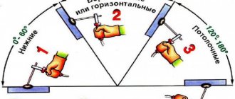
The bath welding method has proven itself excellent when used in the construction of massive structures made of reinforced concrete, complex reinforcement frames, and in the construction of critical buildings and structures. This method allows you to maintain the rigidity and strength parameters of a reinforced concrete structure along its entire height and length and guarantees the creation of a single load-bearing reinforcement frame. The pool welding method can be used for both horizontal and vertical connections, which greatly simplifies the process of connecting frame parts. This welding method can be performed with standard fixtures used in the standard electric arc welding process.
The main condition for ensuring high quality connections when using these welding methods is the precise alignment of the joints of the reinforcing bars. The use of bath technology implies the absence of displacement of the axes of the welded rods relative to each other. The maximum deviation is no more than half the cross-section of the rod. Achieving the required accuracy is ensured by the use of special jigs that fix the location of the rods and ensure the invariability of the geometric parameters of the reinforcing bars during the welding process.
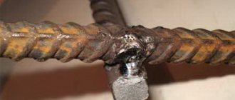
The basic principle of the welding method: at the junction of the reinforcing bars, a steel form (bracket-plate) is welded to them. By means of electric arc welding, a bath of metal in a molten state is formed in it. The ends of the reinforcement melt at high temperatures and thus form a single pool of welding seam material. When the metal cools in the bath, the required compound is formed.
Before welding, the ends of the rods and the side surface are thoroughly cleaned in order to remove dirt, scale and traces of corrosion. These activities are carried out with a stiff brush with steel bristles, then after cleaning the rods are placed coaxially with each other. It is necessary that there remains a gap between the ends of the rods, the size of which is no more than one and a half diameters of the reinforcing rods. When welding seams located vertically, the role of a bracket-plate is performed by a stamped sheet form. It is welded to the lower reinforcement rod without the use of filler materials, while simultaneously producing oscillatory gradual movements (in relation to the axes of the rods the oscillations are perpendicular) with an electrode, and thus the joint is melted along the entire section. Any excess slag masses that appear must be removed using a scoop designed for this purpose. After these activities are completed, the end of the upper reinforcing bar is joined to the lower one and the deposited metal is directed into the mold. The release of slag occurs by burning a hole in the wall of the mold with an electrode. Subsequently, the holes are welded.
How to weld reinforcement using the bath welding method - features.
There are three options for bath welding:
- in ceramic form (semi-automatic);
- single- and three-phase electric arc in a steel bracket-plate (manual method) - baths for welding reinforcement;
- in copper form (automatic slag bath).
The most economical method is considered to be welding without the use of overlays; in this case, no labor or material costs are required for their production. In addition, connecting the rods without using overlays guarantees a more compact joint. The connection of reinforcement by bath welding occurs at high currents, reaching a value of 450 amperes when using 5–6 mm electrodes. If the welding process occurs at low air temperatures, use a current 10 percent higher than the standard current. When performing work using the pool welding method, experts recommend using UONI-13/55 electrodes.
In the case of using three-phase electric arc welding, a gap of 2 cm greater than the diameter of the electrodes used should be left, but the misalignment of the axes of the reinforcing bars in this option should not be more than five percent of the diameter of the electrodes. Often, the ends of reinforcing bars become covered with slag during bath welding due to rapid heat dissipation. Slagging helps reduce the reliability of connections, but the likelihood and degree of slagging can be reduced by:
- warming up the ends of the rods before starting work;
- use metal molds made of heat-conducting components (copper).
In the bathtub method of welding the reinforcement, the joint is covered from below with a bracket-plate made of sheet steel with a low carbon content. The bracket holds the liquid metal, preventing it from leaking out.
2 Normative references
This standard uses normative references to the following standards:
GOST 5264-80 Manual arc welding. Welded connections. Main types, structural elements and dimensions
GOST 6727-80 Cold-drawn low-carbon steel wire for reinforcement of reinforced concrete structures. Specifications
GOST 8713-79 Submerged arc welding. Welded connections. Main types, structural elements and dimensions
GOST 10922-2012* Reinforcement and embedded products, their welded, knitted and mechanical connections for reinforced concrete structures. General technical conditions
________________
* On the territory of the Russian Federation, GOST R 57997-2017 “Welded reinforcement and embedded products, welded connections of reinforcement and embedded products of reinforced concrete structures” is in force. General technical conditions".
GOST 14771-76 Arc welding in shielding gas. Welded connections. Main types, structural elements and dimensions
GOST 27772-88 Rolled products for building structures. General technical requirements
GOST 34028-2016 Reinforcing bars for reinforced concrete structures. Specifications
Note - When using this standard, it is advisable to check the validity of the reference standards in the public information system - on the official website of the Federal Agency for Technical Regulation and Metrology on the Internet or using the annual information index "National Standards", which was published as of January 1 of the current year, and on issues of the monthly information index “National Standards” for the current year. If the reference standard is replaced (changed), then when using this standard you should be guided by the replacing (changed) standard. If the reference standard is canceled without replacement, then the provision in which a reference is made to it is applied in the part that does not affect this reference.
(Changed edition, Amendment No. 1), (Amendment. IUS No. 9-2019).
Single-electrode method algorithm
To carry out work on fastening various products from A500C reinforcement, the best way is welding using copper plates. This weld pool is made without grooves to hold the metal, but the inside is made with a smooth surface, which makes it easy to dock the reinforcement.
The method is used when installing structures exposed to static and vibration loads. Welding machines can be used with direct and alternating current power; the main thing is that they must be of sufficient power and performance.
Bath welding begins from one of the sides, gradually moving towards the center. The electrode should advance slowly, making circular or crescent movements. This method will ensure uniform filling of the bath cavity and heating of the base metal.
When melting, the electrode is lowered, ensuring the formation of the shortest arc. The metal rises to the top edge of the bath, completely covering the fittings. After this, the welding bath is considered completed. When the seam has cooled, you can adjust the parts.
When stopping welding, be sure to knock off the slag and light an arc at the finished edge of the seam. This will make it possible to reliably cover the place where the seam stops and is interrupted. The seam should be completed in the middle of the bath to prevent holes and voids. Such places need to be cleaned of slag and boiled again.
5 Technical requirements
5.1 When choosing rational types of welded joints and welding methods, you should be guided by Appendix A.
5.2 For the design of welded joints not provided for by this standard, working drawings should be developed with a technological description of welding conditions and a departmental regulatory document or enterprise standard that takes into account the requirements of current standards and approved in the prescribed manner.
5.3 In the manufacture of reinforced concrete structures, it is allowed to replace the types of connections and methods of their welding with equivalent ones in terms of performance in accordance with Appendix A.
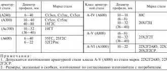
5.4 The chemical composition and carbon equivalent value of reinforcing steels of classes A240, A400S, A500S, A600S, Ap600S, A800S, A1000S welded according to this standard must comply with the requirements of GOST 34028.
(Changed edition, Amendment No. 1).
5.4.1 (Deleted, Amendment No. 1).
5.5 Cold-deformed reinforcement must meet the requirements:
— class B500С — current regulatory documents*;
__________________
* GOST R 52544 is in force in the Russian Federation.
— class Vr-1 — GOST 6727.
5.6 Reinforcement of unmeasured length of classes Ap600S, A800S and At1000S, as well as waste of this reinforcement, can be used in welded reinforcement products and embedded parts of reinforced concrete structures. In this case, the reinforcement is used as A400C class reinforcement without recalculating the cross-section.
Reinforcement of class A600C is allowed for use as anchors for embedded parts as reinforcement of class A500C without recalculating the cross-section.
(Changed edition, Amendment No. 1).
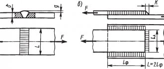
5.7 The designs of cross-shaped reinforcement connections, their dimensions before and after welding must correspond to those shown in Figure 1 and Tables 2-3.
Figure 1 - Cross-shaped connection made by resistance spot welding
5.8 The ratio of the diameters of the rods should be taken for connections of type K1 - from 0.25 to 1.00, type K3 - from 0.50 to 1.00.
5.9 For connections of type K1, the amount of settlement (see Figure 1) is determined by the formula
;
where: - total thickness of the rods after welding at the intersection, mm;
— total size of dents, mm.
The relative precipitation values for type K1 compounds must correspond to those given in Table 2.
5.10 The designs of reinforcement butt joints, their dimensions before and after welding must correspond to those given in Table 4-10.
5.11 The designs of lap joints of reinforcement, their dimensions before and after welding must correspond to those given in Tables 11-13.
5.12 Designs of T-joints of reinforcement with flat elements of embedded products, their dimensions before and after welding must correspond to those given in Tables 14-17.
5.13 The main types, structural elements and dimensions of welded joints made of sheet and shaped metal products used to connect flat elements of embedded parts during the installation of reinforced concrete structures must meet the requirements of GOST 5264, GOST 8713 and GOST 14771.
5.14. For the connections given in Tables 7-8, sheet steel of class C235-C255 according to GOST 27772 should be used as the material for the brackets.
Table 2 - Designs of cross-shaped connections of K1-Kt reinforcement
| Designation of connection type, welding method | Reinforcement connection | Reinforcement class | , mm | The value ensuring strength is not less than that required by GOST 10922 for connections with a diameter ratio | The minimum value providing non-standardized | |||||
| before welding | after welding | 1,00 | 0,50 | 0,33 | 0,25 | strength | ||||
| K1-Kt | VR-1 (B500) | 3-12 | 0,35-0,50 | 0,28-0,45 | 0,24-0,40 | 0,22-0,35 | 0,17 | 30°-90° | ||
| В500С | 4-12 | |||||||||
| A240 | 5,5-40 | 0,25-0,50 | 0,21-0,45 | 0,18-0,40 | 0,16-0,35 | 0,12 | ||||
| А400С | 6-40 | 0,40-0,80 | 0,35-0,70 | 0,30-0,62 | 0,28-0,55 | 0,20 | ||||
| А500С | 6-40 | 0,40-0,60 | 0,35-0,50 | 0,30-0,46 | 0,28-0,42 | |||||
| А600С | 10-40 | |||||||||
| Note - Values that do not coincide with those given should be rounded to the nearest value specified in this table. | ||||||||||
Table 3 - Designs of cross-shaped connections of K3-Rp and K3-Mp reinforcement
| Designation of connection type, | Reinforcement connection | Reinforcement class | ; , mm | , mm | , mm | |
| welding method | before welding | after welding | ||||
| K3-Rp, K3-Mp | A240 | 10-40 | 0.5, but not less than 8 | 0.35, but not less than 6 | ||
| A400 | 10-28 | |||||
| А500С | 10-40 | |||||
| А600С | ||||||
| Notes 1 The value of temporary shear resistance in connections K3-Rp and K3-Mp is not standardized. If it is necessary to make connections with standardized strength, the dimensions are specified experimentally based on the results of shear tests (GOST 10922) and are drawn up in accordance with 5.2. In this case, it is not allowed to make connections of the K3-Rp and K3-Mp types with standardized strength on the construction site. 2 When mechanized welding of joints of the K3-Mp type, it is allowed to use reinforcement with a diameter of () 6 and 8 mm, as well as reducing the ratio of the diameters of the welded rods to 0.33. The use of these provisions is permitted under increased requirements for the acceptance of welded joints and mandatory compliance with the requirements of 5.2. | ||||||
Table 4 — Design of butt joint of S1-Ko reinforcement
| Type designation | Reinforcement connection | Reinforcement class | , mm | , mm | 10 | |
| connection, welding method | before welding | after welding | ||||
| S1-Ko | A240 | 10-40 | 0,85-1,0 | 90° | ||
| А400С | ||||||
| Ap600S, A800S | 10-32 | |||||
| А1000С | 10-22 | |||||
| А500С | 10-40 | |||||
| А600С | ||||||
| В500С | 10-12 | |||||
Table 5 - Designs of butt joints of S5-Mf and S7-Rv reinforcement
| Designation of connection type, | Reinforcement connection | Reinforcement class | , mm | , mm | , mm | 10 | , mm | , mm | , mm | |||
| welding method | before welding | after welding | ||||||||||
| S5-Mf, S7-Rv | А240, А400С | 20-40 | 0,5-1,0 | 12-20 12-16 | 5-12 | 90° | 10°-15° | |||||
| Notes 1 Dimensions in the denominator refer to the C7-Rv connection. 2 At ratio 1, linear dimensions refer to a rod with a larger diameter. | ||||||||||||
Table 6 — Designs of butt joints of S8-Mf and S10-Rv reinforcement
| Designation of connection type, | Reinforcement connection | Reinforcement class | , mm | , mm | , mm | , mm | 10 | , mm | , mm | , mm | |||||
| welding method | before welding | after welding | |||||||||||||
| S8-Mf, S10-Rv | А240, А400С | 20-40 | 0,5-1,0 | 5-15 3-10 | 8-20 | 90° | 40°-50° | 10°-15° | 20°-25° | ||||||
| Notes 1 When single-electrode welding, cutting rods with a bevel of the lower rod should not be carried out. 2 Cutting with a reverse bevel of the lower rod should be used when welding rods with a diameter of 32 mm. 3 Dimensions in the denominator refer to the C10-Rv connection. 4 With a ratio of 1, the linear dimensions refer to a rod with a larger diameter. | |||||||||||||||
Table 7 — Designs of butt joints of S14-Mp and S15-Rs reinforcement
| Designation of connection type, | Reinforcement connection | Reinforcement class | , mm | , mm | , mm | , mm | , mm | , mm | |||
| welding method | before welding | after welding | |||||||||
| S14-Mp, S15-Rs | A240 | 20-40 | 0,5-1,0 | 10-20 | 8°-10° | (0,35-0,40) | |||||
| A400 | |||||||||||
| At500 | 20-32 | ||||||||||
| А500С | 20-40 | ||||||||||
| А600С | |||||||||||
| Note - For 20-25 mm 6 mm, for 28-40 mm 8 mm. | |||||||||||
Table 8 — Designs of butt joints of S17-Mp and S19-Rm reinforcement
| Designation of connection type, | Reinforcement connection | Reinforcement class | , mm | , mm | 10 | , mm | , mm | , mm | , mm | , mm | |||
| welding method | before welding | after welding | |||||||||||
| S17-Mp, S19-Rm | A240 | 20-40 | 0,5-1,0 | 6-8 | 90° | 30°-40° | (0,35-0,40) | ||||||
| А400С | |||||||||||||
| А500С | |||||||||||||
| А600С | |||||||||||||
| Note - For 20-25 mm 6 mm, for 28-40 mm 8 mm. | |||||||||||||
Table 9 — Designs of butt joints of S21-Rn and S21-Mn reinforcement
| Designation of connection type, | Reinforcement connection | Reinforcement class | , mm | , mm | , mm | , mm | , mm | |
| welding method | before welding | after welding | ||||||
| S21-Rn, S21-Mn | A240 | 10-40 | , but >10 | , but >8 | , but >4 | |||
| A400 | ||||||||
| A600 | 10-32 | |||||||
| A800 | ||||||||
| A1000 | 10-22 | |||||||
| А500С | 10-40 | |||||||
| А600С | ||||||||
| В500С | 10-12 | |||||||
| Notes 1 Connections of reinforcement of classes Ap600C, A800C, A1000C should be made with offset linings, applying seams in a checkerboard pattern. 2 Double-sided seams of length 4 are allowed for connections of reinforcement of classes A240, A400C. 3 For reinforcement with a diameter of 25-40 mm, it is allowed, instead of reinforcement linings, to use reinforced brackets of the type shown in tables 7 and 8, for classes A400C and A500C - at least 6 in length, for class A600C - at least 8 in length. Internal size of brackets - there must be at least 2 pads, while the minimum cross-sectional area of the bracket is determined by the formula , where is the minimum cross-sectional area of the bracket-plate; - nominal cross-sectional area of the connected reinforcement; and is the temporary resistance of the reinforcement and brackets normalized by the standards, respectively. | ||||||||
Table 10 — Designs of butt joints of S23-Re and S23-Me reinforcement
| Designation of connection type, | Reinforcement connection | Reinforcement class | , mm | , mm | , mm | , mm | |
| welding method | before welding | after welding | |||||
| S23-Re, S23-Me | A240 | 10-25 | , but 8 | , but 4 | |||
| A400 | |||||||
| А500С | 10-25 | ||||||
| А600С | |||||||
| В500С | 10-12 | ||||||
| Notes 1 It is allowed to use connections of rods with any combination of their diameters within the limits specified in this table, while the dimensions , and in the connection of rods are taken according to the smaller diameter. 2 Double-sided seams of length 4 are allowed for connections of class A240 reinforcement. | |||||||
Table 11 — Designs of lap joints of N1-Rsh and N1-Msh reinforcement
| Designation of connection type, | Connection of reinforcement to plate | Reinforcement class | , mm | , mm | , mm | , mm | , mm | |
| welding method | before welding | after welding | ||||||
| N1-Rsh, N1-Msh | A240 | 10-32 | , but 4 | , but 8 | , but 4 | |||
| А400С | ||||||||
| Ap600S | 10-32 | , | ||||||
| А800С | but 5 | |||||||
| А1000С | 10-22 | |||||||
| А500С | 10-32 | |||||||
| А600С | ||||||||
| В500С | 10-12 | |||||||
Table 12 — Design of lap joint of N2-Kr reinforcement
| Designation of connection type, | Connection of reinforcement to plate | Reinforcement class | , mm | , mm | , mm | , mm | , mm | , mm | , mm | 3 | |
| welding method | before welding | after welding | |||||||||
| N2-Kr | A240 | 6-16 | (0,10-0,15) | , but not less than 4 | 90° | ||||||
| А400С | |||||||||||
| А500С | |||||||||||
| А600С | |||||||||||
| В500С | 6-12 | ||||||||||
Table 13 — Design of lap joint of N3-Kr reinforcement
| Designation of connection type, | Connection of reinforcement to plate | Reinforcement class | , mm | , mm | , mm | , mm | , mm | , mm | , mm | 3 | |
| welding method | before welding | after welding | |||||||||
| N3-Kr | A240 | 12-16 | (0,10-0,15) | , but not less than 4 | 90° | ||||||
| A400 | |||||||||||
| А500С | |||||||||||
| А600С | |||||||||||
| В500С | 12 | ||||||||||
Table 14 — Design of T-connection of T1-Mf fittings
| Designation of connection type, | Connection of reinforcement to plate | Reinforcement class | , mm | , mm | , mm | , mm | ||
| welding method | before welding | after welding | ||||||
| T1-Mf | A240 | 8-40 | 4 | (1,8-2,5) | 0,1 | 15° | 0,50 | 85°-90° |
| А400С, А500С | 8-25 | 6 | 0,65 | |||||
| 28-40 | 0,75 | |||||||
| В500С | 8-12 | 4 | 0,65 | |||||
Table 15 — Design of T-connection of T2-Rf fittings
| Designation of connection type, | Connection of reinforcement to plate | Reinforcement class | , mm | , mm | , mm | , mm | ||
| welding method | before welding | after welding | ||||||
| T2-Rf | A240 | 8-40 | 4 | (1,8-2,5) | 0,3 | 15° | 0,50 | 85°-90° |
| А400С, А500С | 8-25 | 6 | 0,65 | |||||
| В500С | 8-12 | 4 | ||||||
Table 16 — Design of T-joint of T11-Mz reinforcement
| Designation of connection type, | Connection of reinforcement to plate | Reinforcement class | , mm | , mm | , mm | , mm | , mm | , mm | , mm | ||
| welding method | before welding | after welding | |||||||||
| T11-Mz | А240, А400С, А500С, А600С | 12 | 8 | 0,5 | 0-1 | 4-5 | 22-26 | ||||
| 14 | 26-30 | ||||||||||
| 16 | 28-32 | ||||||||||
| 18 | 10 | 0-2 | 5-6 | 30-35 | |||||||
| 20 | 35-42 | ||||||||||
| 22 | 12 | 38-44 | |||||||||
| 25 | 46-48 | ||||||||||
| Notes 1 For fittings of classes A400C, A500C and A600C, the value is 0.55. 2 When using embedded parts with anchors made of A600C steel, you should follow the instructions of 5.6. | |||||||||||
Table 17 — Design of T-connection of T12-Rz reinforcement
| Designation of connection type, method | Connection of reinforcement to plate | Reinforcement class | , mm | , mm | , mm | , mm, at | , mm | at 12±1, mm | ||||
| welding | before welding | after welding | 6-7 | 8-26 | ||||||||
| T12-Rz | A240 | 8-40 | 6 | 1-2 | 2-3 | 50° | 0,50 | 2 | 4 | |||
| А400С | 0,75 | |||||||||||
| А500С | 10-40 | 8 | ||||||||||
| А600С | ||||||||||||
| В500С | 8-12 | 6 | ||||||||||
| Notes 1 At 12 mm, it is allowed to make connections without a weld. 2 When using embedded parts with anchors made of steel class A600C, you should follow the instructions of 5.6. | ||||||||||||
Tables 2-17 (Changed edition, Amendment No. 1).
Advantages and disadvantages
The welding material and molten reinforcement metal fill the bath without spreading and form a reliable seam that can withstand significant loads. The material of the part itself serves as additional reinforcement for the seam.
Other advantages of pool welding include:
- minimal costs due to rational use of surfacing material;
- the technology for performing all operations ensures high quality welds under similar conditions to other welding methods;
- This method has been repeatedly tested and verified; there is a lot of literature and manuals on how to carry out the work;
- For every rod size, there is a suitable tray - this is due to the wide range of products.
There are also disadvantages to the bath method. The use of steel baths can only be one-time use due to welding to the base metal. Copper baths, although they can be used several times, are quite expensive. It is also necessary to carry out preparatory work, which takes time.
The disadvantages are purely subjective, so the bathroom connection method is the most common.