Types
Seams produced by manual arc welding in accordance with GOST 5264-80 are divided into types according to the location of the joined elements. The regulatory document identifies the following compounds:
- butt;
- corner;
- overlap;
- onlay.
The butt joint is considered classic and is more common than other types. It connects – joins the ends of parts, sheets and pipes. The connection is strong and can withstand tensile, torsional, and bending loads. As a result of butt welding, one element of a part smoothly flows into another and continues it.
A butt connection is used most often when a pipeline is laid and large flat parts, such as platforms, are created . The thickness of the connected elements can be the same or different. Depending on the thickness of the material, the edges are cut. Seams are manually welded in one or several layers.
The corner joint can have a mutual position of 90⁰, as well as an acute and obtuse angle between the elements being connected.
Application area
Installation of pipelines, creation of frame structures, ceilings, fences involves the arrangement of parts at right angles. Reinforcing elements are usually attached perpendicularly by welding: beams, channels, rolled profiles. Parts at an angle of 90° are connected by T-welding. Beginning welders at home try to avoid such joints because of the difficulty of fixing parts in a given position.
In production and construction, T-joints are often used. All types of connections are regulated by GOSTs for various types of welding. They can be single-sided or double-sided, with or without edge cutting. It all depends on the expected load, alloy, thickness of the parts being welded.
Types of T-welded joints
Edge shape
For sheet material whose thickness is less than 4 mm, welding according to GOST 5264-80 is carried out without cleaning the edges. Dirt, scale, and burrs are removed from the joined ends. A sheet of the same thickness is welded with a flange or with linings.
A plate up to 60 mm thick is welded by cutting one or both edges. The cutting has a rectilinear shape and is done on one or both sides, depending on the seam. When welding on one side, removable pads are used to form the root of the joint.
For plates over 60 mm, welds according to GOST 5264-80 are made with a curved bevel for multi-layer welding. Double-sided cutting of edges can be done identically on both sides in the shape of the letter V, which in cross-section looks like an X. Or a curved asymmetrical cutting is made, with less on the bottom side.
Advantages and disadvantages
Unlike other welding methods, T-joints have the following advantages:
- they form a reliable connection in hard-to-reach places;
- they do not require the use of reinforcing pads;
- used for welding workpieces of various thicknesses;
- withstand heavy load.
Flaws:
- to maintain perpendicularity, parts must be fastened before welding;
- one-sided seams are unreliable;
- when welding thin-walled parts, there is a high probability of thermal deformation;
- there is a high risk of internal defects (lack of penetration, discontinuities, craters).
Character of the seam
The document for manual welding according to GOST 5264-80 defines the nature of the weld as:
- unilateral;
- double-sided
A one-sided butt connection is made using various technologies for forming a root weld. One-way connections are divided:
- free;
- lined;
- castle
Corner, T and lap joints do not have options for making a root seam. They can be welded on one or both sides.
There are installation and main welding seams. The first is necessary to temporarily hold a steel part in a certain position. After all the reinforcement has been welded, the assembly joint is removed mechanically
We disassemble squares No. 2 and 3, types of seams according to GOST standards
Two standards closely deal with connection options: the already familiar GOST 14771-76 and the famous GOST 5264-80 on manual arc welding.
What is famous about the second standard: it was written many years ago - in 1981, and it was done so competently that this document still works perfectly.
An example of a drawing of welds according to GOST.
The types of welding joints are as follows:
C – butt seam. The metal surfaces to be welded are connected by adjacent ends, located on the same surface or in the same plane. This is one of the most common options, since the mechanical parameters of butt structures are very high. At the same time, this method is quite complex from a technical point of view; experienced craftsmen can do it.
T – T-seam. The surface of one metal workpiece is connected to the end of another workpiece. This is the most rigid design of all possible, but due to this, the T-bar method does not like and is not intended for bending loads.
N – lap seam. The surfaces to be welded are parallel offset and slightly overlap each other. The method is quite durable. But it carries less load than the butt options.
U – fillet weld. Melting occurs at the ends of the workpieces; the surfaces of the parts are kept at an angle to each other.
O – special types. If the method is not in GOST, a special type of welding is indicated in the drawing.
Both standards within the framework of the ECSD resonate well with each other and fairly divide responsibilities by type:
Options for depicting welds in drawings.
Manual arc connections according to GOST 5264-80:
- C1 – C40 butt
- T1 – T9 T-bar
- H1 – H2 overlap
- U1 – U10 corner
Gas shielded welding connections according to GOST 14771-76:
- C1 – C27 butt
- T1 – T10 tee
- H1 – H4 overlap
- U1 – U10 corner
In our abbreviation, in the second square, GOST 14771-76 is indicated, and in the third T3 - the double-sided T-bevel method without beveled edges, which is precisely indicated in this standard.
Cross-sectional shapes
In the cross-section of the welded joint, its shape is clearly visible. The metal of the electrode or additive, together with the molten edges, forms a cone that expands towards the top. The side boundaries partially follow the shape of the edges, but run in arcuate lines along the base metal.
On the reverse side, the root seam protrudes slightly beyond the plane of the parts being joined, forming an arc. The use of pads prevents metal from flowing out of the weld pool. The metal on the back side of the joint does not leak out and forms a smooth surface with the planes of the parts being connected. The edge is overlapped by the joint line.
Part thickness
The standard clearly distinguishes the types of edge preparation and the number of layers depending on the thickness of the parts . The main table indicates what shape the cut should be and the nature of the seam.
When producing welded joints in accordance with GOST 5264-80 with different wall thicknesses not exceeding the permissible dimensions of 1 - 4 mm, the parts are welded as having the same thickness. The joint may be located at an angle.
In the case of a greater difference in the thicknesses of the joined plates, the larger part is ground at an angle of 15⁰, to the thickness of the smaller part. Mechanical processing is carried out, if necessary, on both sides. The welding mode is selected according to the part with a smaller thickness.
In corner joints, the end of the welded plate may not be cut and welding is carried out from 2 sides according to the specified pattern. In this case, a gap is allowed - b. It increases in proportion to the thickness of the sheet and ranges from 1 mm to 4 mm, without trimming the edges.
Advantages
Like any other compound, there is a set of positive aspects that make it more popular in certain areas. The main advantages of the connection include the following:
- Allows you to provide connections in hard-to-reach places that would not be possible by other means;
- It is possible to scald the contact area on both sides, which will increase strength;
- Can be used to connect both thick and thin parts;
- There is no need to use additional pads, since if there is a reliable fixation, the seam can be simply butted;
- The structure can withstand quite heavy loads after treatment with such compounds.
Flaws
There are also specific disadvantages that make it difficult to use seams in certain areas. These include:
- The difficulty of making the connection, since the part to be welded must be fixed before welding (if this is not done reliably enough, the geometry of the structure will be disrupted);
- When welding a part on one side, the connection is not very reliable, since the impact on the opposite side acts as a lever for breaking the seam;
- Very thin parts become difficult to weld due to inconvenience and a high risk of deformation, especially when welding on both sides;
- A small contact area does not always ensure a reliable connection;
- When used in the professional field, an accurate preliminary calculation of the T-weld joint is always required so that breakdowns do not occur during operation.
Features of a T-joint
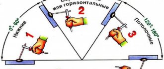
It allows you to easily connect parts of different thicknesses, since when connecting, one part serves as a smooth, flat surface and its thickness does not matter much. But when welding there are still small peculiarities, a larger part is welded to a smaller one or vice versa. If a smaller part is being welded, then when welding you need to hold the electrode at an angle of 60 degrees. If it’s the other way around, then you need to make sure that the bulk of the recess goes into the thicker part, so the electrode should be at an angle of more than 60 degrees.
If the structure can be rotated, then professionals advise securing the parts with tacks and tilting the structure so that welding takes place in the lower position “in a boat.” This will significantly improve the quality of the connection, so that a welder of even initial qualifications can now handle it. On an industrial scale, automatic welding machines are used that create T3 welds and other varieties without direct human intervention.
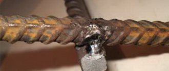
Appearance of T-joint
"Important!
In the vast majority of cases, the seam is completed in just one pass, since it is very important to avoid undercuts. Any undercut at the base of the seam negatively affects its quality.”
Types and parameters
There are several standard varieties that are regulated by generally accepted standards.
T3 weld table:
| Type of seam | Description |
| Single-sided seam with a bevel on one edge. | The bevel is made at an angle that depends on the thickness of the structure. |
| One-sided seam with a curved bevel of one edge. | A curved bevel is more difficult to make, but helps provide a more complex seam if the situation calls for it. |
| Double-sided seam with two symmetrical edge bevels. | As in a one-sided bevel, everything is done here at a certain angle. |
| Double-sided seam with two symmetrical curved edge bevels. | Standard bevels are made at a certain angle, while curved bevels have an uneven surface, beveled taking into account the design features. |
Designation on the drawing
Welding seam T3 and other varieties can often be found on drawings, but not everyone knows what these numbers and letters can mean. Decoding the T1 weld looks as simple as possible:
- T – T-joint;
- 1 – number in the classification.
Example of T-joint designation
The designation of T1 welds according to different GOSTs may be the same, since they only require a different type of creation, using manual arc or gas welding. The connections themselves, including the T6 weld, T4 weld and others will also be the same. The difference will lie in specific options that are not in one of the classifications, but will be present in the other. Inspection of T-welded joints is carried out on the basis of the classification taken here.
Conclusion
The T1 weld and other varieties are widely used in modern welding practice. For them, you need to use a special approach in terms of pre-processing the edges in order to achieve a high-quality result. The weld leg of a T-joint should also be positioned, each time adjusting to the working conditions, metal thickness, working material and other factors.
Legend
Welded seams in accordance with GOST 5264-80 are designated in the drawing indicating the characteristics of the connection, cutting and design option. The alphanumeric designation is located on the flange of the arrow that points to the seam. The transcript indicates:
- GOST according to which the part is manufactured.
- Alphanumeric designation.
- Welding method, apparatus.
- Leg.
- For intermittent seams, the length of the welded sections.
In the drawing, visible seams are drawn with a thick line, invisible ones with a dotted line. In the side image, the shape of the part of the seam protruding beyond the surface of the connected elements is drawn.
A letter with a number – designation of the nature of the electric arc welding joint:
- butt-connected, C1 – C25;
- ends at an angle, U1 – U10;
- tee, T1 – T11;
- lap and overhead, H1 – H3.
For seams made using semi-automatic machines, in protective gases and other methods, the type of connection is indicated by the same letters. The difference in welding technology is determined by numbers and is carried out according to other regulatory documents. For example, if shielding gas is used, GOST 14771-76 is indicated.
At the end of the marking, the characteristics of the connection, if necessary, establish additional designations. An inclined line characterizes the intermittent seam of a butt joint. Z is placed on a T-joint and an overhead joint with a staggered arrangement of welded sections.
The metal structure has closed and open connections along the contour. They are designated by a circle and a square without one side. The grade of the material being welded can be indicated in the marking or routing sheet.
Head of the design bureau for the design of large metal structures at the KhSMK plant Dolgopolov S.V.: “If the same type of seams is used in the manufacture of a part, the designation can be simplified to an arrow with a small flange. It may only have a schematic designation of the characteristics of the seam and may not even have a shelf, only an arrow. The easiest way to determine the location of the connection, on which side of the projection of the drawing it is located, is by marking: the visible seam is above the line, the invisible seam is GOST, and all the characteristics are written below the flange line.”
Techniques and features of welding T-joints
When making corner joints, they control the size of the suture leg and the appearance of the roller - they make it as flat as possible. To weld the T-joint evenly, do not make sudden movements with the holder. The arc during welding should not break off during the formation of the bead. The preparatory stage includes:
- stripping of metal in the work area;
- laying workpieces at the desired angle while maintaining the required gap size;
- fixing elements with clamps or tacks.
Pipe welding
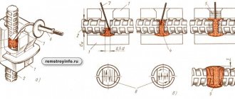
When RDS of plugs, flanges, shut-off valves in pipelines is carried out, they are guided by the requirements of GOST 16037-80. It is also used when inserting pipes of smaller diameter. On thick-walled workpieces, preliminary cutting of seams is carried out. Then tacks are made in 4 places, they are arranged in pairs symmetrically around the circumference, dividing it into 4 parts. Then a fillet seam is made.
When inserting, the end of the pipe is adjusted to fit the pipe so that it fits tightly to the surface without forming large gaps. Pipes of small diameter are “finished” with a grinder. When cutting large workpieces for welding, reamer stencils or standard templates are used.
When there are rotary tables, rotary position welding technology is used. The seam forms faster and is even. It is more difficult to weld fixed seams; the bead is formed along curved lines. In this case, welding is carried out in several stages, in sections. The second one begins on the resulting roller, overlapping, so that the T-joint becomes airtight. Depending on the wall thickness, the pipe is welded in one pass or several. Such T-joints must be checked using non-destructive testing methods.
Yield strength
The quality of the welded joint is determined by visual inspection and examination of macro- and micro-structure and mechanical properties . Steel has its own yield point - the load at which deformation begins. Control is carried out using a destructive method. Cut out a fragment of the seam with the metal it connects. The mechanical qualities of the weld metal and welded elements are checked for tension, bending and other indicators.
The strength and yield strength of the weld should not exceed those of the base metal . Using the table, select the type of electrode whose connection will meet the requirements for strength and fluidity.
Small cubes with sides of 10 mm are cut out from the area under study. After grinding and acid etching, they show a grain structure and microcracks formed during tension to the yield point.
Minimum leg of a conditional seam
When welding an I-joint, the leg is taken according to the smallest dimension of the inscribed triangle. The surface of the deposited metal can have a convex or concave shape. The curve should not deviate from a straight line by more than 30%.
The minimum value of the leg relative to the thicker element is determined from the table, based on the fluidity of the steel. The values are divided into yield strength up to 400 MPa and above this value.
For a thin part, the leg should not exceed 1.2 times its thickness.
Table of the dependence of the leg on the resistance.
Square No. 5, seam dimensions
These are the required seam dimensions. It is most convenient to indicate the length of the leg, since we are talking about a T-type version with a perpendicular connection at a right angle. The leg is determined depending on the yield strength.
It should be noted that if the drawing shows a connection of standard sizes, the length of the leg is not indicated. In our drawing designation, the leg is equal to 6 mm.
Classification of welds.
Additional connections are:
- SS one-sided, for which the arc or electrode moves on one side.
- BS double-sided, the melting source moves on both sides.
The third participant in our drawing and welding party comes into play - GOST 2.312-72, which is dedicated to images and symbols.
According to this standard, seams are divided into:
- Visible, which are depicted as a solid line.
- Invisible, indicated in the drawings by a dotted line.
Now let's go back to our original seam. We are able to translate this welding symbol into simple text that is understandable to the human ear:
Double-sided T-seam by manual arc welding in protective carbon dioxide with edges without bevels, intermittent with a staggered arrangement, weld leg 6 mm, length of the welded area 50 mm, pitch 100 mm, remove the convexities of the seam after welding.