Semi-automatic welding technologies
Butt. This is a continuous spot weld.
Overlapping. In this case, a small piece of metal is placed on the seam and scalded in two ways. These are: continuous seam or spot welding.
Welding on prepared holes.
During the entire process, gas and electricity interact
This forces the welder to pay special attention to the safety system
Welding GOST 14771-76 is the main quality standard for this type of welding work. GOST includes a list of various gases, materials and work techniques. If all technical characteristics meet established standards, then the work will be performed at the proper level.
Used auxiliary signs
- - used when there is a requirement to level the joint surface;
- — ensure a smooth transition to the main surface through mechanical grinding of metal smudges and irregularities;
- — permanent connection is made along an open circuit;
- , — the joint is made in the form of a closed continuous contour;
- — carry out the welding operation when fitting the part in place;
- — intermittent connection with a periodic type of location of the weld pool;
- — discontinuous joint, staggered arrangement of the weld pool.
Welding designations (excerpts from regulatory documentation) for different methods of operation (manual electric arc, argon) are summarized in the table:
Methods for making a weld are reflected in GOST:
- A - automatic joining with flux in the absence of a lining, pillow, without a preliminary seam;
- Af - automatic welding using flux and a pad based on it;
- IN - docking is carried out using a refractory tungsten alloy electrode in a cloud of gases without adding additional material;
- INp - docking is performed with a tungsten electrode in a cloud of inert gases with the addition of additional material;
- IP - the use of a melting electrode in a cloud of gases;
- UP is a connection in a carbon monoxide environment through a melting electrode.
In general, deciphering and reading the designation of welds in documentation is almost the same as learning to read the ABC or Primer. It is required to remember the regulatory documents (GOST) and correctly decipher the symbols shown on the drawings.
Semi-automatic welding process
The welder independently moves the electrode along the edge manually. The molten metal of the electrode falls into a special bath. The welding wire is fed through a flexible hose to the welding site. The feed rate should not be less than the melting rate. For this type of welding, wire with a diameter of 0.8 to 1.6 millimeters is used.
Equipment for semi-automatic welding
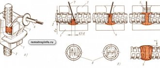
Welding of reinforcement, GOST provides for the use of certain equipment.
- Welding rectifiers. This equipment is used to convert current. There are three classes of rectifiers: based on the number of posts served and power phases. The third class depends on the type of valve.
- Semi-automatic welding.
- A cylinder filled with a special protective gas.
- Gearbox.
- Hoses.
Types of Welding Wire
- Steel welding.
- Steel surfacing.
- Wire made of aluminum or alloys.
- Cast iron rods.
- Flux cored and alloyed wire.
Designation of welding methods in standards
Designation of welding methods in standards (for main types, structural elements and sizes made in various ways)
1. Manual arc welding of joints made of steels, as well as iron-nickel-based alloys, is carried out in accordance with GOST 5264. The standard does not establish designations for this welding method. The thickness of the welded metal is from 1 to 175 mm.
2. Arc welding in shielding gases of welded joints made of steels, as well as alloys on iron-nickel and nickel bases, is carried out in accordance with GOST 14771. The following designations of welding methods are adopted in the standard: IN - in inert gases with a non-consumable electrode without filler material (metal thickness from 0.5 to 6.0 mm), INP - in inert gases with a non-consumable electrode with filler material (metal thickness from 0.8 to 20 mm), IP - in inert gases and their mixtures in carbon dioxide and oxygen with a consumable electrode (metal thickness from 0.5 to 120 mm), UP - in carbon dioxide with a consumable electrode (metal thickness from 0.5 to 120 mm).
3. Arc welding of spot welded joints made of steel, copper, aluminum and nickel alloys is carried out in accordance with GOST 14776 (lap joints). The standard uses the following designations for welding methods: F - submerged arc (top sheet thickness - 0.8...5.0 mm, sheet thickness with a round hole - 3.5...14 mm), UP - in carbon dioxide with a consumable electrode (top sheet thickness - 0.8...6.6 mm , sheet thickness with a round hole - 4.5...30 mm), UN - in carbon dioxide with a non-consumable electrode (thickness of the top sheet - 0.4...3.3 mm, thickness of the sheet with a round hole - 4.5...30 mm), IP - in inert gases with a consumable electrode ( thickness of the top sheet - 0.8...6.6 mm, thickness of the sheet with a round hole - 4.5...15 mm), IN - in inert gases with a non-consumable electrode (thickness of the top sheet - 0.4...3.3 mm), PP - consumable coated electrode with forced non-through penetration and formation (top sheet thickness – 0.8…12 mm without edge preparation).
4. Submerged arc welding of welded joints made of steels, as well as alloys on iron-nickel and nickel bases, is carried out in accordance with GOST 8713. The following designations of welding methods are adopted in the standard: AF - automatic on a flux pad (metal thickness - 2.0 ... 60 mm), AFm - automatic on a flux-copper lining (thickness - 3.0...30 mm), AFo - automatic on the remaining lining (thickness - 2.0...60.0 mm), AFP - automatic on a copper slide (thickness - 5.0...20 mm), MF - mechanized on weight (thickness - 1.5...30 mm).
5. Electroslag welding of welded joints made of steel is carried out in accordance with GOST 15164. The following designations of welding methods are adopted in the standard: ШЭ - wire electrode (metal thickness - 30...450 mm), ШМ - consumable nozzle (thickness more than 30 mm), ШП - electrode, the cross-section of which corresponds in shape to the cross-section of the welding space (gap), thickness - 30...800 mm.
6. Welded connections of steel pipelines are made in accordance with GOST 16037. The following designations of welding methods are adopted in the standard: ZP – shielded gas arc welding with a consumable electrode, ZN – shielded gas arc welding with a non-consumable electrode, R – manual arc welding, F-arc welding submerged arc, G – gas welding.
Welding of GOST reinforcement – semi-automatic welding
SNiP - welding can be performed in two main ways. These are: submerged and using protective gases.
In this case, all work is done both manually and automatically. The welding wire is fed automatically. In this case, the specialist must set the required wire feed speed on the welding equipment. The welder moves the torch on his own.
During this type of material connection, the arc is in a “cloud” of shielding gas, which is delivered to the welding site using special equipment. Argon, carbon dioxide and a wide variety of mixtures of various substances are used for welding.
The principle of choosing a welding method and type of connection
About 150 types of welding are used to join parts. One thing they have in common is the designation of seams in welded joints. Any development involves carrying out calculations established by the technical specifications for it. To determine the method of fastening parts, designers perform calculations that determine the geometry of the joints and the thickness of the structures being welded.
Calculations allow you to determine the type of welding that should be used: manual using electrodes, arc with shielding gases, etc. In your work, you must be guided by the requirements of standards containing the necessary information.
GOST 14771-76 – semi-automatic welding, work technique
During work, shielding gas displaces air from the place where the connecting work is performed. Using special rollers, the wire is fed to the junction of the parts. The rollers are rotated by a special motor, which is located in the inside of the welding machine. Since the melting of the wire occurs under the influence of current, it must be delivered to the welding site.
This happens using a special bent contact. Gas is supplied to the site from a cylinder. Feed rate and dosage are performed automatically. In addition, in some cases, gas supply and adjustment can be done manually.
The molten metal of the electrode and wire is fed to the junction through a nozzle. The liquid substance is supplied in the form of drops and steam.
General principles
The ESKD includes GOST 2.312-72, “Conventional images and designations of seams of welded joints.”
On its pages, the design engineer will find all the necessary information and it will not be difficult to show the welding symbol in the working documentation.
Indeed, there is nothing complicated in designating seams in the drawings, especially if you follow the requirements described in the specified GOST.
For detailed designation of seams in the drawing, a leader line with a shelf is used, on which the seam parameters, conditions for additional processing, etc. are indicated.
The visible part of the welding joint in the drawing is conventionally depicted using the main line, the invisible part is shown with a dashed line.
If the joint is made in several passes, then in the section it is permissible to show each layer as a separate contour. Moreover, each of them must be assigned a letter designation. Thus, when reading the drawing, it will become clear that layer A is applied first, layer B second, and so on.
We recommend! Argon welding of stainless steel
Types of welded joints and seams
Welding of ferrous metals and stainless steel, defined by GOST 14771 76, provides for the following main types of welded joints:
- butt;
- T-bars;
- overlap;
- corner.
Butt
Two sheet or pipe blanks are in the same plane, the seam fills the small gap between them. This is the most common type. It ensures minimal consumption of welding materials and labor intensity. The seam can be one-sided, welded only from the top, or double-sided, which is welded sequentially (or simultaneously) on both sides.
When welding workpieces of medium and large thickness (more than 4 mm), to ensure deep penetration, the edges of the workpieces are cut, chamfering them. The type of cutting depends on the one-sidedness of the seam and the thickness of the sheet
With a sheet thickness of 12 mm or more, it is recommended to use a double-sided seam and an x-shaped groove. This improves penetration and saves welding materials.
Tavrovoe
Connects two sheets (or strips) of the same or different thickness. Depending on it, a one-sided or two-sided seam is used, with or without cutting.
For better penetration of metal workpieces when making such a weld, the workpieces are placed at an angle of 45° to the vertical
Recommended position for welding T-joints and corner joints.
The T-joint should be welded on both sides. When the workpiece thickness is more than 4 mm, cutting is used. In industrial conditions, welding is carried out mechanized on special stands.
Angular
The connection is used in the assembly of various bodies and vessels. If possible, it is also recommended to weld the internal seam at an angle of 45°, just like the T-seam.
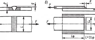
overlap
Used to increase the strength of the joint, in this case it is boiled on both sides. It is also used for the repair of pipelines and steel vessels, using a one-sided seam.
Classification according to other criteria
Welding seams GOST 14771-76 are also divided according to other parameters.
According to the degree of profile convexity, they are divided into categories such as:
- convex;
- ordinary;
- concave.
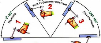
According to spatial position, they are distinguished:
- bottom: most convenient for forming a high-quality seam;
- horizontal, there is a risk of melt leakage;
- vertical: medium risk of leakage;
- ceiling: the most complex, special modes, techniques and materials are used.
Welding positions.
The lower position also achieves the highest welding speed and overall productivity. No highly qualified worker is required.
What are welding joints, their types
Welding processes refer to technological operations that result in the formation of monolithic joints. A weld is a zone in which melting and solidification of the materials of the parts being fastened occurs.
Features of the design of welding fasteners influence the physical and mechanical characteristics of the structure and the consumption of electrode material. When making convex seams, in almost all cases, additional processing is necessary in the form of removing unevenness, which is done mechanically. Based on the shape of the surface, welding seams and their defects are distinguished.
The current standards define several types of joints, for recognition of which the letter designations of the seams of welded joints are used.
Designation of welded joints
Butt view
The letter “C” is used to mark seams. Using this method, parts located in the same plane are welded by joining adjacent ends. These types are among the most durable and durable; they are widely used in the manufacture of metal structures classified as critical. To perform fastening, it is necessary to thoroughly prepare the surface.
Types of butt joints
End mount
And they are designated by the letter "C". The formation of these joints is carried out at the ends of the workpieces. The end joint is often used for welding thin metal products. Using this fastening, reliable fixation of parts is ensured.
Lap view
The joints are marked with the letter “H”. When carrying out welding work using such techniques, less stringent requirements are imposed on the quality of work. But the strength characteristics and load capacity of the joints are much worse than those of the two previous options. To carry out fastening, the parts are arranged in parallel, offset relative to each other and partially overlapping.
T-mount
The letter “T” is used to designate the seams of welded joints. Docking using the T-joint method is one of the most durable and rigid, but it does not tolerate bending loads well. To carry out the work, one of the parts is located in a horizontal plane, and the second is vertical, and is welded end-to-end.
Types of T-Joints
Angle view
Joints are designated by the letter “U”. These types are used less frequently than others. They are reliable and durable. Depending on the need, the parts are located relative to each other at different angles.
Welding joints of all types can be made single-sided, when welding is performed on only one side of the workpiece (marked “SS”), and double-sided, marked “BS”. In the latter case, the parts are welded on both sides.
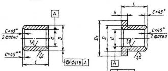
Edge processing
When carrying out welding work, it is necessary to separate the edges. Correct fitting allows you to achieve:
- minimal consumption of materials;
- optimal time for welding performed in one pass;
- the strength of the joint, which is not inferior in its characteristics to the base metal.
Many options are used, differing in angles, gap size, etc. The cutting shape is selected depending on the welding method and the thickness of the metal workpiece. To ensure proper fastening, a gap of 4 mm should be left between the edges.
Edge cutting can be done:
- At right angles.
This option is used for single-sided welding of metal with a thickness of no more than 3 mm, double-sided fastening of metal with a thickness of no more than 8 mm, and for joining steel with a thickness of 4...8 mm.
- In a V-shape (one-sided bevel). The metal thickness can be 4…26 mm.
- In an X-shape (double-sided bevel). This cutting is used when fastening parts with a thickness of 12...40 mm.
- At an angle of 45 degrees. This option is used for metals with a thickness of 2 cm.
Types of edges
Penetrant control
It is based on the property of superfluid liquids to penetrate through capillaries - the smallest holes in the seam material
The method has the following advantages:
- ease of use;
- cheapness;
- safety;
- rapidity.
The method also has disadvantages:
- a limited list of defects is identified;
- a certain orientation of the test product in space is required, which can be difficult when it is large;
- High purity consumables are required.
The capillary control method is used by both industrial enterprises and small workshops and even home craftsmen. It does not require special training or expensive equipment, such as ultrasonic or laser testing. Complex and dangerous radiation-related equipment, organization of its safety, required by GOST for radiographic control, is not required
The standard describes the following stages of control:
- Cleaning the surface being tested. It is necessary to remove both mechanical impurities (chips, scale, dust) and completely clean the surface of oil and fat deposits that prevent the penetration of the indicator liquid into the material of the product.
- Drying.
- Application of a penetrating compound, or penetrant. The composition is usually colored red or blue. It is necessary to observe the temperature conditions specified in the instructions. Usually it is from +5 to +50°C.
- Removing excess composition, drying the product with compressed air.
- Application of the developing component. Usually this composition is white.
- Visual inspection of the surface. In places where defects are located, the layer of developing composition is painted. The size and location of the defect are judged by the shape of the spots and the intensity of the color.
- Documenting the test results, washing the surface from traces of indicator and developing compounds.
After completion of the repair work, in accordance with the requirements of GOST, in order to detect defects in welds, the capillary inspection is carried out again.
What is a welded joint
The welding process is a technological operation of forming a monolithic joint. The area where the material of the joined parts melted and solidified is called a weld.
Kinds
The welded joint is divided into:
- Stykova. The connection is formed along the end surfaces of the parts. It is carried out with or without edge processing. Marking "C".
- Overlapping. The planes of the parts are parallel to each other and partially overlap one another. Marking "N".
- Tavrovy. The end of the part is adjacent to the plane of another part at an angle. The seam is located along the joint. Marking "T".
- Angular. The main planes of the joined parts in the welding zone are located at an angle to each other. Marking "U".
- Tortsovy. The semi-finished product is pressed against the side surfaces. The seam is formed by fusing metal onto the ends of the products.
The seam is performed:
- Unilateral. Deposition is carried out on one side of the connection (joint).
- Bilateral. Processing occurs on both sides.
Necessity of welding designation
Any structure consists of individual parts (assemblies) connected to each other in one way or another.
One of them is welding. The joint has its own characteristics that affect the performance of the product as a whole. The welding designation in the drawing is an explanation of the joining method, the shape of the seam and its geometric parameters, the method of execution and other additional information. A competent engineer will gain additional information:
- about strength - the connection is continuous or intermittent; in addition, thermal stresses are formed in the weld zone;
- about the size and shape of the deposited metal;
- joint tightness;
- time of connection - before installation or during its process, and others.
Checking welds for leaks with kerosene
When installing vessels and pipelines, it is necessary to check the tightness of each welded joint. Seams on other structures also need to be checked for tightness and the absence of microdefects. Such checks are regulated by GOST 3242-79, entitled “Welded joints, methods of quality control”. The kerosene test method uses the unique property of this substance - very high fluidity. Kerosene has a low viscosity, dissolves fatty films and is able to penetrate into the smallest pores and cracks.
A finely dispersed indicator composition (for example, chalk) is applied to one side of the seam, and the other is moistened with a small amount of kerosene. The liquid seeps through the leaks of the welded joint and colors the indicator powder. This way you can localize defects that are not visible to the naked eye, without resorting to hardware non-destructive testing methods.
Several types of kerosene flaw detection method are used:
- conventional: indicator composition and liquid are applied under atmospheric pressure;
- pneumatic: the joint being tested is blown with compressed air, accelerating the penetration of kerosene into the pores;
- vacuum: on the side of the indicator composition, a vacuum is created that “pulls” the indicator medium out of the pores and cracks;
- vibration: in the controlled product, high-frequency vibrations (ultrasound) are excited using piezoelectric vibrators; they also increase the permeability of the suture material for kerosene molecules.
If it is necessary to increase the resolution of the method, kerosene colored with various colored pigments is used - color flaw detection. In this way, cracks and pores up to one tenth of a millimeter in size are detected. The thickness of the tested parts reaches 25 mm.
The accuracy of the method is greatly influenced by the degree of purification of the kerosene-based indicator liquid. Contaminants, especially oil and fat, significantly reduce its penetrating ability and the ability to check the seam. Therefore, special highly purified kerosene is used for control, and the surface of the product is thoroughly degreased.
Designation of seams in the drawing
In the production of any structures, parts are joined in various ways. One method is welding. The resulting seam has certain properties that affect the performance characteristics of the entire product.
It is important to correctly designate the weld on the drawing so that the connection methods, joint shapes, geometric parameters, etc. are clear. A competent specialist can glean information from the drawing about the strength, tightness of the joint, and the time of work.
Arrows, letters, numbers and auxiliary icons are used to indicate metal connections.
Full joint markings include:
- auxiliary signs;
- reference to the standard;
- alphanumeric designation;
- indication of the type of welding;
- leg sizes;
- values of the length of the welded area or the diameter of the point;
- additional signs.
Full seam designation on the drawings
Standard seam designation structure
In the numbered cells, the designer must indicate the main characteristics of the seam.
We recommend! Direct and indirect plasma welding
So, in the first cell it is necessary to show additional signs shown in the figure. In the second, the designer prescribes GOST for the welding method. The third should contain the designation of the seam, for example, T4. Next, the size of the seam leg must be indicated. This designation indicates the parameters of the intermittent seam and other auxiliary signs.
The data placed on the drawings serve as the basis for control of finished products. That is, an employee of the technical control department, guided by the requirements of working documentation and technical specifications, must carry out the appropriate measurements. Let's say he can check the leg size using a traditional measuring tool. The quality of welding can be checked using technical control tools, such as ultrasound.
If a product uses many joints of the same type, the designer has the right to draw up a table of parts connections indicating the welding parameters and seam number.