Today, many devices are manufactured with the ability to adjust the current. Thus, the user has the ability to control the power of the device. These devices are capable of operating in networks with alternating and direct current. The design of the regulators is quite different. The main component of the device can be called thyristors.
Also integral elements of regulators are resistors and capacitors. Magnetic amplifiers are used only in high-voltage devices. Smooth adjustment in the device is ensured by a modulator. Most often you can find their rotary modifications. Additionally, the system has filters that help smooth out noise in the circuit. Due to this, the output current is more stable than the input.
Simple regulator circuit
The current regulator circuit of a conventional type of thyristors assumes the use of diodes. Today they are characterized by increased stability and can last for many years. In turn, triode analogues can boast of their efficiency, however, they have little potential. For good current conductivity, transistors are used of the field type. A wide variety of boards can be used in the system.
In order to make a 15 V current regulator, you can safely choose a model marked KU202. The supply of blocking voltage occurs due to capacitors, which are installed at the beginning of the circuit. Modulators in regulators are usually of the rotary type. They are quite simple in design and allow you to change the current level very smoothly. In order to stabilize the voltage at the end of the circuit, special filters are used. Their high-frequency analogues can only be installed in regulators above 50 V. They cope with electromagnetic interference quite well and do not put a large load on the thyristors.
Operating principle of the regulator relay
Thanks to built-in resistors and special circuits, the relay is able to compare the amount of voltage generated by the generator. After which, too high a value leads to the relay being turned off, so as not to overcharge the battery and damage electrical appliances connected to the on-board network.
Any malfunctions lead to precisely these consequences: the battery becomes faulty or the operating budget increases sharply.
Summer/winter switch
Regardless of the season and air temperature, the operation of the generator is always stable. As soon as its pulley begins to rotate, electric current is generated by default. However, in winter the insides of the battery freeze, and it replenishes the charge much worse than in summer.
The summer/winter switches are either on the body of the voltage regulator, or the corresponding connectors are marked with this designation, which you need to find and connect the wiring to them depending on the season.
Rice. 19 Voltage regulator with winter and summer terminals
There is nothing unusual in this switch, these are just rough settings of the regulator relay, which allows you to increase the voltage at the battery terminals to 15 V.
Connection to the generator's on-board network
If, when replacing a generator, you connect a new device yourself, you need to take into account the following nuances:
- First you should check the integrity and reliability of the contact of the wire from the car body to the generator housing
- then you can connect terminal B of the regulator relay with the “+” of the generator
- Instead of “twists” that begin to heat up after 1–2 years of operation, it is better to use soldering of wires
- the factory wire must be replaced with a cable with a minimum cross-section of 6 mm2 if, instead of a standard generator, an electrical appliance rated for a current of more than 60 A is installed
- The ammeter in the generator/battery circuit shows which power source is currently higher in the on-board network
Rice. 20 Connecting a generator using the example of a VAZ
Ammeters are necessary devices with which you can determine the battery charge and the performance of the generator. It is not recommended to remove them from the scheme without special reasons.
Remote controller connection diagrams
An external generator voltage regulator relay is installed only after determining which wire it should be connected to. For example:
- on old RAFs, Gazelles and Bullheads, relays 13.3702 are used in a polymer or steel case with two contacts and two brushes, mounted in a “–” open circuit, the terminals are always marked, “+” is usually taken from the ignition coil (B-VK terminal) , contact Ш of the regulator is connected to the free terminal of the brush assembly
- in “Zhiguli” relay regulators 121.3702 of white and black colors are used, there are double modifications in which, if one device fails, the operation of the second device continues by simply switching to it, mounted in the “+” gap with terminal 15 to the terminal of the ignition coil B-VK, terminal 67 is attached to the brush assembly with a wire
Car enthusiasts call built-in relay regulators “chocolate bars”, labeled Y112. They are mounted in special brush holders, pressed with screws and additionally protected with a cover.
On VAZ cars, relays are usually built into the brush assembly, full marking Y212A11, connected to the ignition switch. If the owner replaces the standard generator on an old domestic VAZ with an AC device from a foreign car or a modern Lada, the connection is made according to a different scheme:
- The car owner decides on the issue of fastening the body independently.
- The analogue of the “plus” terminal here is contact B or B+; it is connected to the on-board network via an ammeter
- Remote relay regulators are usually not used here, but built-in ones are already integrated into the brush assembly, from them comes a single wire marked D or D+, which is connected to the ignition switch (to the coil terminal B-VK)
Rice. 21 Replacing the standard relay with a three-level regulator
For diesel internal combustion engines, generators may have a W terminal, which is connected to the tachometer; it is ignored when installed on a car with a gasoline engine.
Checking the connection
After installing a three-level or other relay regulator, a performance check is necessary:
- the engine starts
- The voltage in the on-board network is controlled at different speeds
After installing the alternator and connecting it according to the above diagram, the owner can expect a “surprise”:
- when the internal combustion engine is turned on, the generator starts, the voltage is measured at medium, high and low speeds
- after turning off the ignition with the key... the engine continues to run
In this case, you can turn off the internal combustion engine either by removing the excitation wire, or by releasing the clutch while simultaneously pressing the brake. It's all about the presence of residual magnetization and constant self-excitation of the generator winding. The problem is solved by installing the light bulb's exciting wire into the gap:
- it lights up when the generator is not running
- goes out after it starts
- the current passing through the lamp is insufficient to excite the generator winding
This lamp automatically becomes an indicator that the battery is charging.
DC devices
The DC regulator circuit is characterized by high conductivity. At the same time, heat losses in the device are minimal. To make a constant current regulator, the thyristor requires a diode type. The pulse supply in this case will be high due to the rapid voltage conversion process. The resistors in the circuit must be able to withstand a maximum resistance of 8 ohms. In this case, this will minimize heat losses. Ultimately, the modulator will not overheat quickly.
Modern analogues are designed for approximately a maximum temperature of 40 degrees, and this should be taken into account. Field-effect transistors are capable of passing current in a circuit only in one direction. Taking this into account, they must be located in the device behind the thyristor. As a result, the level of negative resistance will not exceed 8 ohms. High-frequency filters are rarely installed on a DC regulator.
DIY crafts for car enthusiasts
We have already looked at many voltage regulator circuits for a variety of purposes, today I will show you three simple DC regulator circuits that are worth adopting, as they are universal and can be used not only in chargers, but also in many home-made designs , including laboratory power supplies.
The current regulator, in theory, is not much different from the voltage regulator; it is worth noting that there is the concept of a current stabilizer.
Unlike a regulator, it maintains a stable output current regardless of the input voltage and output load.
Today we will look at a couple of stabilizer options and one regulator for general use. A current stabilizer is an integral part of any normal laboratory power supply or charger; it is designed to limit the current supplied to the load.
An important point... in all three options, shunts are used as a current sensor, essentially low-resistance resistors; to increase the output current of any of the listed circuits, it will be necessary to reduce the shunt resistance experimentally.
By the way, you will find links to all printed circuit boards at the end of the article. The required current value is set manually, usually by rotating a variable resistor.
All three options that we will consider today operate in linear mode, which means the power element is a transistor. Under heavy loads it will heat up and need cooling.
I will try to explain the principle of operation of the circuits in as simple words as possible...
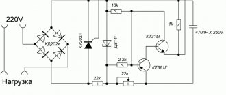
The first circuit is characterized by maximum simplicity and accessibility of components, only two transistors, one of them is the control one, the second is the power one, through which the main current flows.
The current sensor or shunt is a low-resistance wire-wound resistor; when an output load is connected, a certain voltage drop is formed across this resistor; the more powerful the load, the greater the drop.
This voltage drop is enough to trigger the control transistor; the greater the drop, the more this transistor is slightly open.
Resistor R1 sets the bias voltage for the power transistor; it is thanks to it that the main transistor is in the open state.
Current limitation occurs due to the fact that the voltage at the base of the power transistor, which was formed by resistor R1, is roughly damped or shorted to the power supply positive through the open junction of the low-power transistor. This will close the power transistor, therefore the current flowing through it decreases down to complete zero.
Resistor R2 is essentially an ordinary voltage divider, with which we can set the degree of openness of the control transistor, and therefore control the power transistor, limiting the current flowing through it.
The total switching current of this circuit can be increased by using additional power transistors connected in parallel.
Since the characteristics of even identical transistors will differ, resistors are added to their collector circuit; they are designed to equalize the currents through the transistors so that the latter are loaded evenly.
The second circuit is built on the basis of an operational amplifier; it has been repeatedly used in chargers for car batteries; unlike the first option, this circuit is precisely a current stabilizer.
As in the first circuit, there is also a current sensor or shunt, the operational amplifier records the voltage drop across this shunt, all according to the circuit already familiar to us.
The amplifier compares the voltage on the shunt with the reference voltage, which is set by a zener diode.
With a variable resistor we artificially change the reference voltage, the operational amplifier, in turn, will try to balance the voltage at the inputs by changing the output voltage.
The output of the operational amplifier is controlled by a high-power field-effect transistor.
That is, the principle of operation differs little from the first circuit, except that there is a reference voltage source in the form of a zener diode.
This circuit also operates in linear mode and the power transistor will get very hot under heavy loads and needs a heatsink; by the way, it is possible to use bipolar transistors.
The latest circuit is built on the basis of the popular LM317 stabilizer integrated circuit; it is a linear voltage stabilizer, but it is possible to use the chip as a current stabilizer.
The required current is set by a variable resistor. The disadvantage of the circuit is that the main current flows precisely through the previously indicated resistor and naturally it needs a powerful one; the use of wirewound resistors is highly desirable.
Enter your email and receive emails with new crafts.
The maximum permissible current for the LM317 microcircuit is about one and a half amperes, it can be increased with an additional power transistor,
in this case, the microcircuit will already act as a control chip, therefore it will not heat up.
In return, the transistor will heat up and there is no escape from this.
Archive for the article;
Author; AKA Kasyan
Popular;
- Simple voltage regulator on LM317, circuit
- Voltage converter +U to -U on CD4049 microcircuit, circuit.
- Voltage stabilizer with adjustable load for charger
- Charger circuits (using LM317, LM338)
- Low-power laboratory power supply based on LM317
- Current stabilizer for LEDs
- Three power supplies for the car from 24 to 12 volts.
- Simple voltage stabilizer for the charger
AC Models
The AC regulator differs in that thyristors are used only of the triode type. In turn, transistors are standardly used in the field-field type. Capacitors in the circuit are used only for stabilization. You can find high-frequency filters in devices of this type, but rarely. Problems with high temperatures in models are solved using a pulse converter. It is installed in the system behind the modulator. Low-frequency filters are used in regulators with a power of up to 5 V. Control of the cathode in the device is carried out by suppressing the input voltage.
Stabilization of the current in the network occurs smoothly. In order to cope with high loads, reverse zener diodes are used in some cases. They are connected by transistors using a choke. In this case, the current regulator must be able to withstand a maximum load of 7 A. In this case, the level of maximum resistance in the system must not exceed 9 Ohms. In this case, you can hope for a quick conversion process.
Homemade battery chargers
Assembling a charger for a car battery with your own hands is realistic and not particularly difficult. To do this, you need to have basic knowledge of electrical engineering and be able to hold a soldering iron in your hands.
Simple 6 and 12 V device
This scheme is the most basic and budget-friendly. Using this charger, you can efficiently charge any lead-acid battery with an operating voltage of 12 or 6 V and an electrical capacity of 10 to 120 A/h.
The device consists of a step-down transformer T1 and a powerful rectifier assembled using diodes VD2-VD5. The charging current is set by switches S2-S5, with the help of which quenching capacitors C1-C4 are connected to the power circuit of the primary winding of the transformer. Thanks to the multiple “weight” of each switch, various combinations allow you to stepwise adjust the charging current in the range of 1–15 A in 1 A increments. This is enough to select the optimal charging current.
For example, if a current of 5 A is required, then you will need to turn on the toggle switches S4 and S2. Closed S5, S3 and S2 will give a total of 11 A. To monitor the voltage on the battery, use a voltmeter PU1, the charging current is monitored using an ammeter PA1.
The design can use any power transformer with a power of about 300 W, including homemade ones. It should produce a voltage of 22–24 V on the secondary winding at a current of up to 10–15 A. In place of VD2-VD5, any rectifier diodes that can withstand a forward current of at least 10 A and a reverse voltage of at least 40 V are suitable. D214 or D242 are suitable. They should be installed through insulating gaskets on a radiator with a dissipation area of at least 300 cm2.
Capacitors C2-C5 must be non-polar paper with an operating voltage of at least 300 V. Suitable, for example, are MBChG, KBG-MN, MBGO, MBGP, MBM, MBGCh. Similar cube-shaped capacitors were widely used as phase-shifting capacitors for electric motors in household appliances. A DC voltmeter of type M5−2 with a measurement limit of 30 V was used as PU1. PA1 is an ammeter of the same type with a measurement limit of 30 A.
The circuit is simple, if you assemble it from serviceable parts, then it does not need adjustment. This device is also suitable for charging six-volt batteries, but the “weight” of each of the switches S2-S5 will be different. Therefore, you will have to navigate the charging currents using an ammeter.
With continuously adjustable current
Using this scheme, it is more difficult to assemble a charger for a car battery with your own hands, but it can be repeated and also does not contain scarce parts. With its help, it is possible to charge 12-volt batteries with a capacity of up to 120 A/h, the charge current is smoothly regulated.
The battery is charged using a pulsed current; a thyristor is used as a regulating element. In addition to the knob for smoothly adjusting the current, this design also has a mode switch, when turned on, the charging current doubles.
The charging mode is controlled visually using the RA1 dial gauge. Resistor R1 is homemade, made of nichrome or copper wire with a diameter of at least 0.8 mm. It serves as a current limiter. Lamp EL1 is an indicator lamp. In its place, any small-sized indicator lamp with a voltage of 24–36 V will do.
Read also: Kinematic diagram of a planetary gearbox
A step-down transformer can be used ready-made with an output voltage on the secondary winding of 18–24 V at a current of up to 15 A. If you don’t have a suitable device at hand, you can make it yourself from any network transformer with a power of 250–300 W. To do this, wind all windings from the transformer except the mains winding, and wind one secondary winding with any insulated wire with a cross-section of 6 mm. sq. The number of turns in the winding is 42.
Thyristor VD2 can be any of the KU202 series with the letters V-N. It is installed on a radiator with a dispersion area of at least 200 sq. cm. The power installation of the device is done with wires of minimal length and with a cross-section of at least 4 mm. sq. In place of VD1, any rectifier diode with a reverse voltage of at least 20 V and withstanding a current of at least 200 mA will work.
Setting up the device comes down to calibrating the RA1 ammeter. This can be done by connecting several 12-volt lamps with a total power of up to 250 W instead of a battery, monitoring the current using a known-good reference ammeter.
From a computer power supply
To assemble this simple charger with your own hands, you will need a regular power supply from an old ATX computer and knowledge of radio engineering. But the characteristics of the device will be decent. With its help, batteries are charged with a current of up to 10 A, adjusting the current and charge voltage. The only condition is that the power supply is desirable on the TL494 controller.
To create a car charger with your own hands from a computer power supply, you will have to assemble the circuit shown in the figure.
The step-by-step operations required for finalization will look like this:
- Bite off all the power bus wires, with the exception of the yellow and black ones.
- Connect the yellow and separately black wires together - these will be the “+” and “-” chargers, respectively (see diagram).
- Cut all traces leading to pins 1, 14, 15 and 16 of the TL494 controller.
- Install variable resistors with a nominal value of 10 and 4.4 kOhm on the power supply casing - these are the controls for regulating the voltage and charging current, respectively.
- Using a suspended installation, assemble the circuit shown in the figure above.
If the installation is done correctly, then the modification is complete. All that remains is to equip the new charger with a voltmeter, an ammeter and wires with alligator clips for connecting to the battery.
In the design it is possible to use any variable and fixed resistors, except for the current resistor (the lower one in the circuit with a nominal value of 0.1 Ohm). Its power dissipation is at least 10 W. You can make such a resistor yourself from a nichrome or copper wire of the appropriate length, but you can actually find a ready-made one, for example, a 10 A shunt from a Chinese digital tester or a C5-16MV resistor. Another option is two 5WR2J resistors connected in parallel. Such resistors are found in switching power supplies for PCs or TVs.
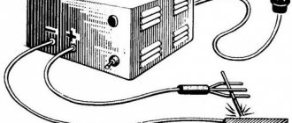
How to make a regulator for a soldering iron?
You can make a current regulator for a soldering iron with your own hands using a triode-type thyristor. Additionally, bipolar transistors and a low-pass filter are required. Capacitors in the device are used in quantities of no more than two units. The decrease in the anode current in this case should occur quickly. To solve the problem with negative polarity, pulse converters are installed.
They are ideal for sinusoidal voltage. The current can be directly controlled using a rotary regulator. However, push-button analogues are also found in our time. To protect the device, the case is heat-resistant. Resonant converters can also be found in models. They differ, in comparison with conventional analogues, in their low cost. On the market they can often be found labeled PP200. The current conductivity in this case will be low, but the control electrode should cope with its responsibilities.
Low Noise AC Power Regulator with NM1041 and NM1042 Kits
Vyacheslav Chulkov
This article describes an AC power controller that produces virtually no interference. The device can be used both as a power regulator for electric heaters and as a power regulator for asynchronous AC motors. Thanks to the use of original circuit solutions and modern element base, it was possible to create a structurally very compact and lightweight device. These devices can be purchased as MASTER KIT kits. The kit includes a printed circuit board and all the necessary parts to assemble a power controller and thermostat.
The kits received the following numbers: “Power controller with low noise level” - NM1041 and “Thermoregulator with low noise level” - NM1042.
Why did this development come about?
The impetus for the emergence of this development was a very specific task. To ventilate the office, a powerful fan based on an asynchronous motor was installed and, to control the ventilation, it was necessary to install an electronic power regulator on the electric motor. For these purposes, a classic thyristor power regulator with phase control was tested. Such a regulator provided power regulation, but due to the supply of supply voltage to the electric motor in the form of pulses with steep edges, the latter produced significant acoustic noise and got hot. In addition, for the same reason, the control system emitted a high level of electrical noise. It was necessary to find another solution.
In Radio magazines, circuits of power regulators that do not create interference were found [1, 2]. In these circuits, power control was carried out by supplying the load with an integer number of periods of the supply voltage, switching them at the moment the supply voltage passes through zero. However, these devices supplied a constant pulse voltage to the load and, in addition, provided only discrete control. Therefore, a new device was developed that uses a similar control principle and provides smooth, stepless power control of the load.
The schematic diagram of the developed device is shown in Fig. 1, and the list of elements is given in Table 1. A powerful field-effect transistor is used as a regulating element. Compared to thyristors, modern high-power field-effect transistors provide a lower forward voltage drop and, as a result, less heat generation. In addition, they require significantly less control circuit power. Additionally, in this circuit, by switching the transistor at zero drain voltage, the effect of dynamic input capacitance is eliminated, which further simplifies the requirements for the control circuit. As a result, it turned out to be possible to power the gate of a field-effect transistor directly from a CMOS chip.
Resistor R4 at the non-inverting input of comparator DA2 sets the required power level. To the other input of the comparator, through the integrating circuit R9C2 (contacts X4 and X5 are closed), a control signal is supplied to the gate of the field-effect transistor. The voltage at the output of the integrating circuit is directly proportional to the on time of the transistor and, consequently, to the output power. The mismatch signal from the output of the comparator is supplied to the input of the field-effect transistor through the latch trigger DD1. The counting input of this trigger receives a strobe signal from optocoupler DA1, which ensures that the trigger switches and the control voltage at the gate of the field-effect transistor changes only when the mains voltage crosses zero. The trigger state is rewritten once for each full period of the mains voltage. This ensures the elimination of switching noise and the absence of a DC component on the load. In the original version of the circuit, the signal to the trigger's counting input was supplied through a resistor divider directly from the power wire. This circuit worked well for a resistive load, but when working with a reactive load, such as an electric motor, it malfunctioned. Therefore, we had to use optocoupler isolation.
Fig.1. Schematic diagram of the power regulator.
Elements R2, VD2, VD4, C1 provide supply voltage for the microcircuits. The VD3 LED is an indication element, simultaneously providing an increase in the comparator supply voltage by approximately 2 V, which is necessary for its normal operation over the range of common-mode input voltages. When using the circuit as a power regulator, a jumper is installed between contacts X4 and X5, instead of resistors R3 and R5, jumpers are also installed, and resistor R8 is not installed.
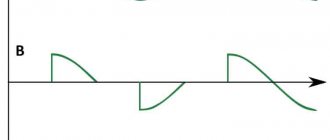
With the indicated elements, the regulator, with an input voltage of 220 V, can regulate power of about 650 W. If it is necessary to work with high powers, you need to install the transistor on a radiator and use diodes VD5-VD8 for a higher permissible current. Figure 2 shows example load voltage diagrams at 25%, 50% and 75% of maximum output power.
In addition to the task of regulating power in the load, the circuit is convenient to use as a noise-free thermostat. In this case, the jumper is not installed between contacts X4 and X5. Between contacts X3 and X4, a thermistor R11 with a nominal resistance at an operating temperature of 10-100 kOhm is connected (for example, MMT-1 or MMT-4), resistor R8 is installed with a value equal to the value of the thermistor, and resistors R3 and R5 are selected experimentally, so that provide the necessary temperature control limits. For example, with ratings R11=R8=22 kOhm and R3=R5=15 kOhm, temperature control was provided in the range from +5°C to +35°C.
Rice. 2. Diagrams of voltage across the load, at different positions of the regulator.
Design.
The regulator is assembled on a printed circuit board measuring 45x67 mm and placed in a standard plastic case of type G025 with dimensions 72x50x21 mm. Due to the small size and weight of the regulator, it can be installed in the break of the power cord without additional fastening. A photograph of the assembled device is shown in Figure 3, and the printed circuit board and arrangement of elements are shown in Figures 4 and 5. Possible replacement elements are shown in Table 1.
Table 1. List of elements.
| Position | Denomination | Note (possible replacement) | Quantity |
| R1 | 100 kOhm | 0.25 W | 1 |
| R2 | 43 kOhm | 0.5 W | 1 |
| R3 | * | Selected during adjustment | 1 |
| R4 | 33 kOhm | Variable, linear | 1 |
| R5 | * | Selected during adjustment | 1 |
| R6, R9 | 47 kOhm | 0.125 W | 2 |
| R7 | 100 kOhm | 0.125 W | 1 |
| R8 | * | Selected during adjustment | 1 |
| R10 | 100 Ohm | 0.125 W | 1 |
| C1 | 100 µF, 16 V | 100 µF, 25 V | 1 |
| C2 | 1.0 µF, 50 V | 1.0 µF, 63 V | 1 |
| DA1 | 4N35 | (4N36, 4N37) | 1 |
| DA2 | LM393 | (HA17393) | 1 |
| DD1 | K561TM2 | (CD4013) | 1 |
| VT1 | IRF740 | (IRF740A) | 1 |
| VD1, VD2 | 1N4004 | (1N4005, 1N4006, 1N4007) | 1 |
| VD3 | LED 3mm | Red LED 3mm | 1 |
| VD4 | BZX55C 12V | Zener diode 12 V | 1 |
| VD5…VD8 | 1N5404 | (1N5406, 1N5407, 1N5408) | 4 |
Fig.3. External view of the power regulator.
Fig.4. Regulator printed circuit board.
Fig.5. Arrangement of elements on the printed circuit board.
A power regulator correctly assembled from serviceable parts does not require adjustment. The thermostat may require selection of resistors R3 and R5. The upper (R5) and lower (R3) temperature control limits depend on these resistors. Since these values are interdependent, when experimentally selecting resistor values, the operation must be repeated several times. When using the regulator at high powers, it is recommended to install transistor VT1 on a small radiator.
Conclusion
The Master Kit division has prepared two kits that include printed circuit boards and all the necessary parts to assemble the power controller and thermostat. The kits received the following numbers: “Power controller with low noise level” - NM1041 and “Thermoregulator with low noise level” - NM1042.
Attention!
Since the device contains high voltages that are dangerous to life, safety regulations must be strictly observed during installation and setup.
Since the thermistor in the thermostat does not have galvanic isolation from the network, in order to avoid electric shock, it is necessary to ensure its reliable insulation!
Literature:
1. A. Evseev. Low noise power regulator. Radio N4, 1986, pp. 46, 47.
2. S. Lukashenko. No-interference power regulator. Radio N12, 1987 pp. 22, 23.
Charger devices
To make a current regulator for the charger, only triode type thyristors are needed. The locking mechanism in this case will be controlled by the control electrode in the circuit. Field-effect transistors are used quite often in devices. The maximum load for them is 9 A. Low-pass filters are not uniquely suitable for such regulators. This is due to the fact that the amplitude of electromagnetic interference is quite high. This problem can be solved simply by using resonant filters. In this case, they will not interfere with signal conduction. Thermal losses in the regulators should also be insignificant.
A simple current stabilizer charger made from scrap materials
There are a huge number of ready-made circuits and designs that allow you to charge a car battery. This article is on the topic of converting a computer power supply to an automatic car battery charger. It tells how to assemble an automatic current stabilizer with the ability to adjust the output current.
The stabilizer circuit used in our assembled charger is quite simple and is based on an open-loop operational amplifier (OP-amp) with a high gain.
The LM358 microcircuit is used as such an operational amplifier, or it would be more correct to call it a comparator. The image shows that it has:
- two inputs (inverting and non-inverting);
- one exit.
The job of the LM358 is to balance the output by increasing or decreasing the voltage at the inputs.
A charger or simple stabilizer is a device that:
- smoothes out network ripples;
- maintains a straight line of the current graph at the same level.
How is this done? In our case, a reference voltage is supplied to one input, set using a zener diode. The second input is connected after the shunt, intended to act as a current sensor. When a discharged battery is connected to the output, the current in the circuit increases and, accordingly, a voltage drop occurs across the low-resistance resistor. On the LM358 chip, a voltage difference appears between the two inputs. The device seeks to balance this difference, thereby increasing the output parameters.
Looking at the diagram, we see that a field-effect transistor is connected to the output, which controls the load. As the battery charges, the voltage at the terminals of the device begins to increase, therefore, it begins to increase at one of the inputs of the op-amp. A voltage difference arises between the inputs, which the op-amp tries to equalize by reducing the output voltage, thereby reducing the current in the main circuit.
As a result, the battery is charged to the required voltage, that is, the set value at the charger terminals. The voltage drop across resistor R3 becomes minimal or will not exist at all. When the voltage at the inputs is equalized, the transistor closes, thereby disconnecting the load from the charger.
Regulators for resistive loads
The current regulator circuit for the active load of thyristors assumes the use of a triode type. They are capable of transmitting signals in both directions. The anode current in the circuit is reduced by lowering the limiting frequency of the device. On average, this parameter fluctuates around 5 Hz. The maximum output voltage should be 5 V. For this purpose, resistors are used only of the field type. Additionally, conventional capacitors are used, which on average can withstand a resistance of 9 ohms.
Pulse zener diodes are not uncommon in such regulators. This is due to the fact that the amplitude of electromagnetic oscillations is quite large and needs to be dealt with. Otherwise, the temperature of the transistors quickly increases and they become unusable. To solve the problem with the falling pulse, a wide variety of converters are used. In this case, specialists can also use switches. They are installed in regulators behind field-effect transistors. However, they should not come into contact with the capacitors.
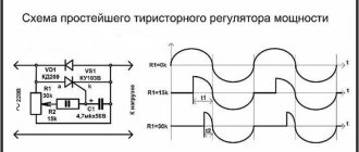
220 volt voltage regulator circuit
Figure 1. Diagram.
The circuit consists of a triac, BTA41-800B, by its name you can determine its current and voltage parameters. For example, BTA is the designation of a triac, 41 is its current in amperes and 800V is its voltage. The triac can be replaced with a weaker current; for this you need to divide the power of your heater by the voltage, for example: 2 kW divided by the network voltage of 220 volts, we get the current we need 2000/220 = 9.1 Amperes. In this case, we can use another BTA12-600B triac, but since the triac will operate almost at the limits of its capabilities, it will heat up and we will have to attach it to a radiator, otherwise it may fail.
Figure 2. Circuit with voltmeter.
Note : Any triac of at least 600V and current depending on the heating element used can be used in the circuit. In any case, to facilitate the operation of the triac, it should be placed on a cooling radiator. Additionally, you can put a voltmeter at the output of the circuit to see the voltage change clearly and put a 16-25 ampere machine at the input.
Details for the diagram:
1. We select a triac depending on the load, but you can, as in my case, the more the better BTA8-600b, BTA12-600b, BTA16-600b, BTA20-600b, BTA24-600b, BTA25-600b, BTA26-600b, BTA40-600b, BTA41- 600b.
2. The potentiometer can be set in the range from 470 kOhm to 1 megaohm (MOhm). I advise you to set the potentiometer to 1 MOhm since it has a larger adjustment range, you can actually adjust it to zero. At the beginning, I assembled a circuit with a 500 kOhm potentiometer and later soldered it to 1 mOhm.
3. DB3 dinistor has no polarity, solder it as we want.
4. Resistor 10 kOhm.
5. Ceramic capacitor 0.1 µF.
How to make a phase model of a regulator?
You can make a phase current regulator with your own hands using a thyristor marked KU202. In this case, the supply of blocking voltage will proceed unhindered. Additionally, care should be taken to ensure the presence of capacitors with a maximum resistance of over 8 ohms. The fee for this case can be charged PP12. In this case, the control electrode will provide good conductivity. Pulse converters in regulators of this type are quite rare. This is due to the fact that the average frequency level in the system exceeds 4 Hz.
As a result, a strong voltage is applied to the thyristor, which provokes an increase in negative resistance. To solve this problem, some suggest using push-pull converters. The principle of their operation is based on voltage inversion. It is quite difficult to make a current regulator of this type at home. As a rule, it all comes down to finding the necessary converter.
Pulse regulator device
To make a pulse current regulator, the thyristor will need a triode type. It supplies control voltage at high speed. Problems with reverse conductivity in the device are solved using bipolar transistors. Capacitors in the system are installed only in pairs. A decrease in the anode current in the circuit occurs due to a change in the position of the thyristor.
The locking mechanism in regulators of this type is installed behind the resistors. To stabilize the limiting frequency, a wide variety of filters can be used. Subsequently, the negative resistance in the regulator should not exceed 9 ohms. In this case, this will allow it to withstand a large current load.
Regulator characteristics
Depending on their type, devices can be manufactured in portable or stationary versions. They can be installed in any position: vertical, ceiling, horizontal.
The devices can be mounted using a DIN rail or built into various units and devices. Structurally, the regulators can be manufactured either in a housing or without being placed in a housing.
The main characteristics of the devices include the following parameters:
- Smooth adjustment. Indicates the minimum step with which the potential difference at the output changes. The smoother it is, the more accurately you can set the output voltage value.
- Operating power. It is characterized by the value of current that can pass through the device for a long time without damaging its electronic connections.
- Maximum power. The peak value that a device can withstand for a short time while maintaining its functionality.
- Input voltage range. These are the input signal values with which the device can operate.
- The range of the variable signal at the device output. Indicates the potential difference that the device can provide at the output.
- Type of adjustable signal. Both alternating and direct voltage can be supplied to the input of the device.
- Terms of Use. Indicates conditions under which the controller characteristics do not change.
- Control method. The output signal level can be set by the user manually or without his intervention.
Soft start models
In order to design a thyristor current regulator with soft start, you need to take care of the modulator. Rotary analogues are considered to be the most popular today. However, they are quite different from each other. In this case, much depends on the board used in the device.
If we talk about modifications of the KU series, they work on the simplest regulators. They are not particularly reliable and do cause some glitches. The situation is different with regulators for transformers. There, as a rule, digital modifications are used. As a result, the level of signal distortion is significantly reduced.
Electronics for everyone
| Triac BT139 |
| Connection diagram from datasheet on MOC3041 |
If you look at it on your fingers, then a thyristor is similar to a diode , even the designation is similar. It allows current to flow in one direction and does not allow it to flow in the other. But it has one feature that fundamentally distinguishes it from a diode - control input . If opening current , then the thyristor will not pass current even in the forward direction. But as soon as you give even a brief impulse, it immediately opens and remains open as long as there is direct voltage. If the voltage is removed or the polarity is changed, the thyristor will close .
The polarity of the control voltage should preferably match the polarity of the anode voltage. If you connect two thyristors back-to-back in parallel , you get a triac - an excellent thing for switching loads on alternating current.
On the positive half-wave of the sinusoid one passes, on the negative half-wave the other. Moreover, they pass only if there is a control signal. If the control signal is removed, then in the next period both thyristors will shut down and the circuit will break. Beauty and nothing more. So it should be used to control household loads.
But there is one subtlety here - we are switching a high-voltage power circuit, 220 volts. And our controller is low-voltage , it operates at five volts. Therefore, in order to avoid excesses, it is necessary to make a potential decoupling . That is, make sure that there is no direct electrical connection between the high-voltage and low-voltage parts. For example, make optical separation . There is a special assembly for this - triac optodriver MOC3041 . Wonderful thing! Look at the connection diagram - just a few additional parts and you have the power and control parts separated from each other. The main thing is that the voltage for which the capacitor is designed is one and a half to two times higher than the voltage in the outlet. You don’t have to worry about power interference when you turn the triac on and off. In the optodriver itself, the signal is supplied by an LED, which means you can safely light it from the microcontroller pin without any additional tricks.
In general, it is possible without decoupling and it will also work, but it is considered good form to always make a potential decoupling between the power and control parts. This includes the reliability and safety of the entire system. Industrial solutions are simply filled with optocouplers or all sorts of isolating amplifiers.
BT139 as a triac - with a good radiator, this thing can easily carry a current of 16A through itself