Let us recall that a triac is usually called a modification of a thyristor that plays the role of a semiconductor switch with a nonlinear characteristic. Its main difference from the basic device is two-way conductivity when switching to the “open” operating mode, when current is supplied to the control electrode. Thanks to this property, triacs do not depend on voltage polarity, which allows them to be used effectively in circuits with alternating voltage.
In addition to the acquired feature, these devices have an important property of the base element - the ability to maintain conductivity when the control electrode is disconnected. In this case, the “closing” of the semiconductor switch occurs when there is no potential difference between the main terminals of the device. That is, when the alternating voltage crosses the zero point.
An additional bonus from this transition to the “closed” state is the reduction in the amount of interference during this phase of operation. Please note that a regulator that does not create interference can be created under the control of transistors.
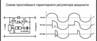
Thanks to the properties listed above, it is possible to control the load power through phase control. That is, the triac opens every half-cycle and closes when crossing zero. The delay time for turning on the “open” mode, as it were, cuts off part of the half-cycle, as a result, the shape of the output signal will be sawtooth.
Signal shape at the output of the power regulator: A – 100%, B – 50%, C – 25%
In this case, the signal amplitude will remain the same, which is why it is incorrect to call such devices voltage regulators.
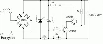
Vacuum cleaner smooth adjustment diagram
Thyristors are often used in devices for continuously regulating the power of active loads such as heating elements (to control the temperature of the heater); commutator motors (to change the rotation speed); incandescent lamps (to change the brightness and color temperature, as well as for smooth switching on in order to increase service life). Despite the inherent disadvantages of thyristor regulators (non-sinusoidal output voltage; high level of noise), they have a simple design and low cost. The best performance can be obtained in PWM control devices with transistor switches. But to work with loads of comparable power, you will need an incomparably more complex circuit containing a key transistor, the price of which is currently several times higher than the price of a thyristor capable of controlling a similar load.
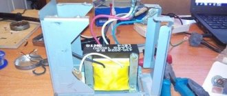
Operating principle of the power regulator
Rice. %img:i1
The basic idea of thyristor power control in an alternating current circuit is that in each period of the supply alternating current, the thyristor is in the open (conducting) state only part of the time. The current flows through the load only when the thyristor is open, and the average power over the period turns out to be less, the smaller the part of the period the thyristor is open. The thyristor is opened by a pulse on the control electrode, which is supplied with a delay relative to the beginning of the period (we take the beginning of the positive half-wave of the supply voltage as the beginning of the period). The delay value determines what part of the period the thyristor will be in the open state, and therefore the average load power. Most types of thyristors used are non-latching, i.e. using the control output they can only be opened; They go into the closed state when a reverse voltage is applied between the anode and cathode or the forward current decreases below a certain level. This can happen, for example, when the supply voltage passes through zero. That is, in this case, the thyristor closes itself at the end of the half-cycle. During those half-cycles when the thyristor is biased in the reverse direction, it is always in the closed state (it is assumed that a triode thyristor is used, which does not conduct in the reverse direction - this is the most common type of thyristor).
Using a tester
Checking the functionality of a triac with a multimeter or tester is based on knowledge of the operating principle of this device. Of course, it will not give a complete picture of the condition of the part, since it is impossible to determine the performance characteristics of the triac without assembling the electrical circuit and taking additional measurements. But often it will be enough to confirm or refute the functionality of the semiconductor junction and its control.
To check the part, you need to use a multimeter in resistance measurement mode, that is, as an ohmmeter. The contacts of the multimeter are connected to the working contacts of the triac, and the resistance value should tend to infinity, that is, be very large.
After this, the anode is connected to the control electrode. The triac should open and the resistance should drop to almost zero. If this is what happened, most likely the triac is operational.
When the contact with the control electrode is broken, the triac should remain open, but the parameters of the multimeter may not be enough to provide the so-called holding current, at which the device remains conductive.
The device can be considered faulty in two cases. If, before voltage appears at the contact of the control electrode, the resistance of the triac is negligible. And the second case, if when voltage appears at the contact of the control electrode, the resistance of the device does not decrease.
Regulator for soldering iron on a microcircuit
The option is not simple, but it has its advantages. Smooth voltage regulation at the load from 0 to 2 kW and no interference. When operating at high power, it is necessary to install a radiator on VS1.
Homemade soldering iron regulator without interference
K561LA7 - K176LA7. KD503A - KD514A, KD522A. KT361V - KT326V, KT361A.
A simple circuit for a 36 volt soldering iron
This scheme is quite working with a minimum of details.
A simple circuit for a low-voltage AC soldering iron regulator
There are similar schemes for regulating the mains voltage. There is only a smaller adjustment limit here.
Using a battery and a light bulb
There is an option to test a triac with a simple tester, which is an open single-line circuit with a power source and a test lamp. You will also need an additional power source for testing. Any battery can be used as it, for example type AA with a voltage of 1.5 V.
The details must be called in a certain order. First of all, it is necessary to connect the contacts of the tester with the working contacts of the triac. The control lamp should not light up.
Then it is necessary to apply voltage between the control and working electrodes from an additional power source. The working electrode is supplied with a polarity corresponding to the polarity of the connected tester. When connected, the indicator lamp should light up. If the triac transition is configured for the appropriate holding current, then the lamp should light even when the additional power source is disconnected from the control electrode until the tester is turned off.
How to connect a regulator to an angle grinder
To connect a homemade power regulator, no special knowledge is required, and any home craftsman can cope with this task. The module is installed in the gap of one wire, through which power goes to the angle grinder. That is, one wire remains intact, and a regulator is soldered into the gap of the second.
In the same way, you can connect a factory power regulator that costs about 150 rubles, which is often purchased by craftsmen in China.
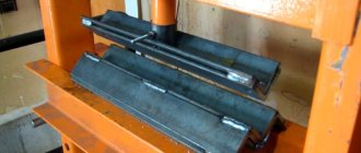
If there is very little space in the grinder, then the regulator can be placed outside the tool, as shown in the following photo.
Also, the regulator can be placed in a socket and used to reduce the speed not only of an angle grinder, but also of other electrical appliances (drill, sharpener, wood milling or lathe, etc.). This is done as follows.
- Purchase a junction box from an electrical goods store (suitable with dimensions 65x65x50 mm).
- You should also buy a small outdoor socket and a power cable with an electrical plug.
- Drill a hole in the side wall of the junction box to insert a variable resistor regulator into it.
- The factory regulator board or a homemade device is placed inside the junction box. All protruding parts in the box that interfere with installation can be cut off.
- The socket should be secured to the cover of the distribution box, having first pulled the wires inside the latter.
- In the figure above you can see that the wires of the network cable touch the radiator, which heats up during operation. That's why it's wearing a PVC tube. But it’s better if you drill a hole for the network cable in a different place to prevent it from coming into contact with the radiator.
The regulator is connected as described above - at a break in one of the wires of the power cable.
The following photos show what a finished socket will look like, having a built-in speed controller for an angle grinder, which can also be used for other electrical appliances.
Using a tester
Checking the functionality of a triac with a multimeter or tester is based on knowledge of the operating principle of this device. Of course, it will not give a complete picture of the condition of the part, since it is impossible to determine the performance characteristics of the triac without assembling the electrical circuit and taking additional measurements. But often it will be enough to confirm or refute the functionality of the semiconductor junction and its control.
To check the part, you need to use a multimeter in resistance measurement mode, that is, as an ohmmeter. The contacts of the multimeter are connected to the working contacts of the triac, and the resistance value should tend to infinity, that is, be very large.
After this, the anode is connected to the control electrode. The triac should open and the resistance should drop to almost zero. If this is what happened, most likely the triac is operational.
When the contact with the control electrode is broken, the triac should remain open, but the parameters of the multimeter may not be enough to provide the so-called holding current, at which the device remains conductive.
The device can be considered faulty in two cases. If, before voltage appears at the contact of the control electrode, the resistance of the triac is negligible. And the second case, if when voltage appears at the contact of the control electrode, the resistance of the device does not decrease.
Operating principle of the speed controller
The speed controller is a device consisting of the following three main subsystems:
- AC motor;
- Main drive controller;
- Drive and additional parts.
When the AC motor is started at full power, current is transferred with the full power of the load, this is repeated 7-8 times. This current bends the motor windings and generates heat that will be generated for a long time. This can significantly reduce engine longevity. In other words, the converter is a kind of step inverter that provides double energy conversion.
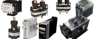
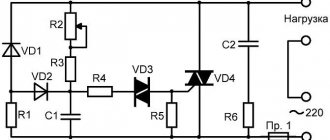
Photo - regulator diagram for a commutator motor
Depending on the incoming voltage, the frequency regulator of the speed of a three-phase or single-phase electric motor rectifies the current of 220 or 380 volts. This action is carried out using a rectifying diode, which is located at the energy input. Next, the current is filtered using capacitors. Next, PWM is generated, the electrical circuit is responsible for this. Now the windings of the induction motor are ready to transmit the pulse signal and integrate them into the desired sine wave. Even with a microelectric motor, these signals are issued, literally, in batches.
How to choose a regulator
There are several characteristics by which you need to choose a speed controller for a car, machine electric motor, or household needs:
- Control type. For commutator motors, there are regulators with a vector or scalar control system. The former are more often used, but the latter are considered more reliable;
- Power. This is one of the most important factors for choosing an electrical frequency converter. It is necessary to select a frequency generator with a power that corresponds to the maximum permissible on the protected device. But for a low-voltage motor it is better to choose a regulator more powerful than the permissible watt value;
- Voltage. Naturally, everything here is individual, but if possible, you need to buy a speed controller for an electric motor, the circuit diagram of which has a wide range of permissible voltages;
- Frequency range. Frequency conversion is the main task of this device, so try to choose a model that will best suit your needs. Let's say, for a manual router, 1000 Hertz will be enough;
- According to other characteristics. This is the warranty period, the number of inputs, the size (there is a special attachment for desktop machines and hand tools).
Why adjust the rotation speed of the grinder disc at all?
- When cutting metal of different thicknesses, the quality of work greatly depends on the speed of rotation of the disk. If you are cutting hard and thick material, you must maintain maximum rotation speed. When processing thin sheet metal or soft metal (for example, aluminum), high speeds will lead to melting of the edge or rapid blurring of the working surface of the disk;
- Cutting and sawing stone and tile at high speed can be dangerous. In addition, the disk, which rotates at high speeds, knocks small pieces out of the material, making the cutting surface chipped. Moreover, different speeds are selected for different types of stone. Some minerals are processed at high speeds;
- Grinding and polishing work is in principle impossible without adjusting the rotation speed. By setting the speed incorrectly, you can damage the surface, especially if it is a paint coating on a car or a material with a low melting point;
- The use of discs of different diameters automatically implies the presence of a regulator. Changing a disk Ø115 mm to Ø230 mm, the rotation speed must be reduced by almost half. And holding a grinder with a 230 mm disc rotating at a speed of 10,000 rpm is almost impossible to hold in your hands;
- Polishing of stone and concrete surfaces, depending on the type of crowns used, is carried out at different speeds. Moreover, when the rotation speed decreases, the torque should not decrease;
- When using diamond discs, it is necessary to reduce the number of revolutions, since their surface quickly fails due to overheating. Of course, if your grinder works only as a cutter for pipes, angles and profiles, you won’t need a speed controller. And with the universal and versatile use of angle grinders, it is vital.
Using a battery and a light bulb
There is an option to test a triac with a simple tester, which is an open single-line circuit with a power source and a test lamp. You will also need an additional power source for testing. Any battery can be used as it, for example type AA with a voltage of 1.5 V.
The details must be called in a certain order. First of all, it is necessary to connect the contacts of the tester with the working contacts of the triac. The control lamp should not light up.
Then it is necessary to apply voltage between the control and working electrodes from an additional power source. The working electrode is supplied with a polarity corresponding to the polarity of the connected tester. When connected, the indicator lamp should light up. If the triac transition is configured for the appropriate holding current, then the lamp should light even when the additional power source is disconnected from the control electrode until the tester is turned off.
Since the device must pass current in both directions, for reliability, you can repeat the test by changing the polarity of connecting the tester to the triac to the opposite one. It is necessary to check the functionality of the device when the current flows in the opposite direction through the semiconductor junction.