Simple power regulator circuit
The very first devices whose task was to control and regulate power were based on Ohm's law. These are the simplest circuits that made it possible to regulate only one voltage source per device.
Ohm's law states that the power of electricity is directly equal to the square of the current. The device used was called a rheostat.
The rheostat can be connected either in series or obliquely, i.e. in the opposite direction. By changing the resistance, you can adjust the voltage power, everything is quite simple.
Solder the power wires according to the diagram
Before turning it on for the first time, you need to ring the entire circuit and make sure that it is assembled correctly. After making sure that the assembly is correct, we connect the load to the output. A light bulb can serve as a visual load to determine the correct operation of the regulator.
By changing the position of the potentiometer slider, we make sure that the intensity of the lamp glow changes.
The circuit works and can be used to regulate the power of any load.
Features of the rheostat
When current enters the rheostat, it begins to divide between the device and the load itself. If a sequential switching circuit is selected, then the voltage and current are monitored. When using a parallel connection circuit, the potential difference is controlled.
The rheostat itself can be completely different.
- Coal
- Liquid
- Metal
- Ceramic
When using a rheostat, you must remember the laws of physics. So the electricity that will be taken cannot simply evaporate. The rheostat will convert it into heat.
This must be taken into account in case you plan to supply large values to the device. In the case of a large load and heat generation, the need to remove excess heat must also be taken into account.
As a cooling system for the rheostat, you can use a blower or a container with oil in which the rheostat is placed. Both options have both advantages and disadvantages.
The rheostat is quite an interesting device; you can assemble a power regulator circuit with your own hands. However, it has one rather significant drawback: it is not possible to use a small device to pass large amounts of electricity through it.
Features of regulators for primary transformers
The battery charging current is 10% of its capacity. This means that a battery with a capacity of 60Ah is charged with a current of no more than 6A. The charging voltage when the car is running is 14.5V. Given the required margin, the charger should be capable of delivering 10A at 16V.
A voltage reserve is necessary to regulate and limit the charging current.
In different models of devices it is done in different ways:
- Additional resistances. They turn on after the diode bridge. The simplest design, but with the largest dimensions.
- Transistors. High adjustment accuracy, but the most complex circuit that requires good cooling of power transistors.
- Thyristor control. Simple diagrams. The adjustment is carried out by a thyristor switch in the primary winding circuit or by thyristors installed instead of diodes in the rectifier bridge.
Modern devices
With the development of semiconductor technology, it was possible to make a significant step from the rheostat to more technologically advanced equipment, which is devoid of the disadvantages of its predecessor. Today, it is possible to use radioelements with an efficiency of 80%, which is very high in comparison with the same rheostat.
The use of such elements makes it quite easy and simple to use modern devices on networks with a voltage of 220 V, which is very convenient. At the same time, modern devices do not require large and complex cooling systems, as was the case in the past.
With the invention of integrated circuits, it was actually possible to make the power control device as miniature as possible, and at the same time increase the value of the maximum voltage that it can pass through itself.
Completion
In conclusion, it would be useful to remind you of a few things. First, be careful when testing the regulator. There is high voltage there, which can, if not kill a person, then lead to burns and pain. Secondly, be careful when selecting a triac from analogues. Consider load power, current and voltage. Thirdly, when manufacturing regulators according to this scheme for a more powerful load, it is worth abandoning the hinged installation. The parts must be soldered on the board and placed in a separate case.
Varieties
Instructions on how to make a power regulator will depend on the specific type of this device chosen. Let's look at what types of devices there are today.
- Phase. One of the most common, used in lamps. Its task is to control the brightness of incandescent or halogen lamps.
- A triac power regulator is a device that regulates power by changing the number of voltage half-cycles, which are the ones that affect the load.
- Tristor. They are not very popular, but in some cases they can become an indispensable thing. The operating principle is based on a certain delay in turning on the tristor switch in the system during the half-cycle of the current.
Travel regulator. One of the most high-tech. Allows you to smoothly change voltage levels, reducing or increasing the electrical power that is supplied to the electric motor or elsewhere.
Practical examples for review
The most popular among radio amateurs are circuits designed to control the brightness of a lamp and change the power of a soldering iron. Such circuits are easy to repeat and can be assembled without the use of printed circuit boards by simple overhead mounting.
Circuits made independently are in no way inferior in performance to factory ones, since they do not require settings and, with working radio components, are immediately ready for use. If you are unable or want to make the device yourself from scratch, you can purchase kits for self-production. Such kits contain all the necessary radio elements, a printed circuit board and a circuit with assembly instructions.
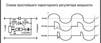
Dominant scheme
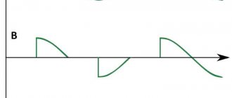
The easiest way to assemble such a device is with a thyristor. The operation of the circuit is based on the ability of the thyristor to open when the input sinusoid passes through zero, as a result of which the signal is cut off and the voltage across the load changes.
The circuit for replicating the thyristor power regulator is based on the use of thyristor VS1, which is used as KU202N. This radio element is made of silicon and has a pnp type structure. Used as a symmetrical switch for medium power signals and switching AC power circuits.
Adjustment
It is worth understanding that the adjustment of the device does not depend on the shape of the input signal. Based on the type of placement, devices are divided into stationary and mobile.
- The differences are obvious, the first type is securely attached to a specific place.
- The second option, on the contrary, has the ability to be in any place where it is convenient for the master.
The voltage regulation device is currently an electrical circuit, thanks to which it becomes possible to regulate the voltage in a particular building if everything is connected correctly.
Work order
First of all, a printed circuit board is prepared from a piece of foil PCB. On the purchased piece of PCB we mark the location of the circuit elements, mark the required dimensions of the board and cut it out.
We degrease the foil, clean it with fine sandpaper, and draw with a pencil a wiring diagram of the regulator that corresponds to the circuit diagram.
Use varnish (you can use nail polish) to outline the pencil drawing. After the varnish has dried, we lower the board into a bath of ferric chloride and etch out the copper foil that is not involved in the operation of the circuit.
- How to fix a laptop that won't charge
Insulated dielectric screwdrivers up to 1000V - tips on how to choose the best manufacturer
- Dielectric insulated tool for work - which one is better to choose? Review of manufacturers, photos + video
We install a triac or thyristor on the radiator to remove heat.In the places where the circuit elements are installed, we drill holes, apply a film of flux to the remaining foil and tin the tracks and areas, creating current-carrying connections. When the board is ready to install the elements, we complete the installation by installing and soldering them.
Recommendations
If you do not have experience and knowledge of how to handle electrical appliances, then it is best not to touch them. If the wiring is incorrect, the network can receive a short circuit, as a result of which this device, as well as several others that were connected to the network, burned out.
Using the services of professionals significantly saves time and money, which you would still have to spend on a specialist if you did everything yourself. During the work, you can ask a professional about the manipulations being carried out.
He will tell you in detail what and how to connect and connect. Will share tips and tricks, conduct a practical lesson with devices.
What does its power depend on?
Next we will talk about the nuances, of which there are only three, and on which the power of a dimmer, both factory and homemade, can depend.
The first nuance is the power reserve of the triac.
It should be about 30% for high-quality work, and the difference in their price will be insignificant.
For example, we can take a standard situation - you order a triac from a seller, who, in turn, will claim that its power reaches 4 kW.
At the same time, he will use various tricks, for example, he will take a close-up photo to deceive the eye and the heat sink will appear larger than it actually is.
Of course, if you turn on such a dimmer for half a minute, it can and will withstand it.
However, usually incandescent lamps or heating elements are connected to it, which work for hours at this power.
Such regulators will not withstand it, even at 3 kW they will heat up to the maximum, and then they will simply burn out.
You must understand what 40 kW is, and also that the regulator will have to pass 18 amperes through itself and what cross-section the wires must have in order to pass such a current.
The second nuance was touched on a little in the last paragraph, but still - the cross-section of the wires is more expensive than the printed circuit board.
The wider and thicker the cross-section of wires and tracks, the better, and the shorter the tracks and wires themselves, the better.
When soldering them, you must tin them with tin or solder a copper core along the tracks.
Additionally, if you are working with a device of 3,000 W or more, then it is better to abandon the various clamp terminals and any connectors.
After all, these places become vulnerable areas - if the contact weakens a little, then they heat up, and then the wires burn, which, of course, is undesirable.
Source stroykadoma.org
The third nuance is the heat sink.
If the heat sink for your home-made dimmer is not large enough, then after long-term use the entire device will become extremely hot (the temperature can reach 90 degrees Celsius and higher), it will be a real oven.
Therefore, I advise you to use a radiator from a computer with a cooler as a heat sink.
Such replacements for the heat sink, even small ones, will show good results during long-term operation at a power of 4,000 W, while Chinese radiators in the heat sinks will allow the device not to fail in the next few minutes after starting at such power.
Additionally, I’ll tell you a little about glass fuses.
Briefly about the main thing! I do not advise.
I somehow brought the fuse holder with a cap to the rear panel, set the fuse to 15 amperes, the load was about 3 kW.
As a result, the entire assembly became so hot that you couldn’t touch it with your hand.
Therefore, it is better to install automatic switches instead of glass fuses (if the load is 3,000 W, then a 16-amp switch).
Source evse.com.ua
Photo of a homemade power regulator
What is a phase regulator
Typically, a phase generator is a small device with a rotating mechanism that allows you to reduce or increase the power supplied to devices. The operation of such devices is based on one small semiconductor device called a triac. It allows you to change the configuration and phase of the signal, which also changes the power of the devices.
What is a phase regulator
Note! You can buy such a device in a store or assemble it yourself for your own circuit. It is used for single- and three-phase networks with slight differences in design.
Triac
Specifications
The phase power regulator has several important characteristics, the change of which entails changes in the operation of the entire circuit. You can understand these characteristics using the example of PR brand regulators, which are among the most popular:
- circuit voltage 220 V;
- AC frequency 50 Hz;
- power regulation ranging from 0 to 97% of the original value;
- the maximum permissible load level is 1500 W;
- current at the anode from 7 A at an operating temperature of 80 °C to 2 A at 100 °C;
- operating temperature limits (on the body) from −10 °C to 100 °C;
- voltage fluctuation amplitude 1.75 V;
- weight up to 15 g.
Model PR
Different applications and circuits require regulators with different characteristics. Depending on the circuit, a different regulator power, voltage rating, or current frequency may be required.
Important! For any power control device, you need to pay attention to the temperature limits, especially the upper limit. During operation, the device itself generates a large amount of heat, and high ambient temperatures can cause damage to the circuit and even fire.
How to use it correctly
The safety and success of the regulator depends on compliance with several rules:
- compliance with temperature conditions. The device may become very hot, especially if the surrounding environment is also hot. In this case, it is worth taking care of the presence of cooling;
- you need to select a regulator taking into account all network parameters;
- the current strength in the circuit should not be equal to the maximum permissible for the regulator;
- When assembling it yourself, it is necessary to provide the device with protection from electric shock by enclosing it in a housing.
Purpose
The power regulator is useful in circuits containing the following electrical devices:
Regulator with motor
- electric motors;
- devices that use compressors in their work;
- household appliances: washing machines, fans, vacuum cleaners;
- electrical tools of various kinds;
- various lighting devices.
A simple example of using a regulator in lighting
. Important! It is not recommended to use a phase regulator in circuits that include refrigerators, computers, televisions and other fine-tuned consumers, changes in the nature of whose operation can lead to damage to the device or other unpredictable consequences.