Today, many devices are manufactured with the ability to adjust the current. Thus, the user has the ability to control the power of the device. These devices are capable of operating in networks with alternating and direct current. The design of the regulators is quite different. The main component of the device can be called thyristors.
Also integral elements of regulators are resistors and capacitors. Magnetic amplifiers are used only in high-voltage devices. Smooth adjustment in the device is ensured by a modulator. Most often you can find their rotary modifications. Additionally, the system has filters that help smooth out noise in the circuit. Due to this, the output current is more stable than the input.
Simple regulator circuit
The current regulator circuit of a conventional type of thyristors assumes the use of diodes. Today they are characterized by increased stability and can last for many years. In turn, triode analogues can boast of their efficiency, however, they have little potential. For good current conductivity, transistors are used of the field type. A wide variety of boards can be used in the system.
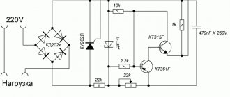
In order to make a 15 V current regulator, you can safely choose a model marked KU202. The supply of blocking voltage occurs due to capacitors, which are installed at the beginning of the circuit. Modulators in regulators are usually of the rotary type. They are quite simple in design and allow you to change the current level very smoothly. In order to stabilize the voltage at the end of the circuit, special filters are used. Their high-frequency analogues can only be installed in regulators above 50 V. They cope with electromagnetic interference quite well and do not put a large load on the thyristors.
Features of the rheostat
When current enters the rheostat, it begins to divide between the device and the load itself. If a sequential switching circuit is selected, then the voltage and current are monitored. When using a parallel connection circuit, the potential difference is controlled.
The rheostat itself can be completely different.
- Coal
- Liquid
- Metal
- Ceramic
When using a rheostat, you must remember the laws of physics. So the electricity that will be taken cannot simply evaporate. The rheostat will convert it into heat.
This must be taken into account in case you plan to supply large values to the device. In the case of a large load and heat generation, the need to remove excess heat must also be taken into account.
As a cooling system for the rheostat, you can use a blower or a container with oil in which the rheostat is placed. Both options have both advantages and disadvantages.
The rheostat is quite an interesting device; you can assemble a power regulator circuit with your own hands. However, it has one rather significant drawback: it is not possible to use a small device to pass large amounts of electricity through it.
DC devices
The DC regulator circuit is characterized by high conductivity. At the same time, heat losses in the device are minimal. To make a constant current regulator, the thyristor requires a diode type. The pulse supply in this case will be high due to the rapid voltage conversion process. The resistors in the circuit must be able to withstand a maximum resistance of 8 ohms. In this case, this will minimize heat losses. Ultimately, the modulator will not overheat quickly.
Modern analogues are designed for approximately a maximum temperature of 40 degrees, and this should be taken into account. Field-effect transistors are capable of passing current in a circuit only in one direction. Taking this into account, they must be located in the device behind the thyristor. As a result, the level of negative resistance will not exceed 8 ohms. High-frequency filters are rarely installed on a DC regulator.
What should be the charging current?
If very strong is used, it may degrade the performance of the charger. In cases where it is too small, charging will occur slowly. It is generally accepted that for car batteries with electrolytes, the optimal current value depends on the capacity, expressed in ampere-hours. It is believed that the maximum permissible current strength is a tenth of this value, and the minimum is a twentieth. An example is a capacity of 60 Ah. In this case, the highest charging current will be 6 A, and the lowest - 3 A.
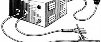
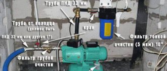
Charger for car battery Source tj-service.ru
AC Models
The AC regulator differs in that thyristors are used only of the triode type. In turn, transistors are standardly used in the field-field type. Capacitors in the circuit are used only for stabilization. You can find high-frequency filters in devices of this type, but rarely. Problems with high temperatures in models are solved using a pulse converter. It is installed in the system behind the modulator. Low-frequency filters are used in regulators with a power of up to 5 V. Control of the cathode in the device is carried out by suppressing the input voltage.
Stabilization of the current in the network occurs smoothly. In order to cope with high loads, reverse zener diodes are used in some cases. They are connected by transistors using a choke. In this case, the current regulator must be able to withstand a maximum load of 7 A. In this case, the level of maximum resistance in the system must not exceed 9 Ohms. In this case, you can hope for a quick conversion process.
How to increase the current in a circuit?
There are situations when it is necessary to increase I, which flows in the circuit, but it is important to understand that measures need to be taken to protect electrical appliances; this can be done using special devices.
Let's look at how to increase the current using simple devices.
To complete the work you will need an ammeter.
Option 1.
According to Ohm's law, current is equal to voltage (U) divided by resistance (R). The simplest way to increase force I, which suggests itself, is to increase the voltage supplied to the input of the circuit, or to reduce the resistance. In this case, I will increase in direct proportion to U.
For example, when connecting a 20 Ohm circuit to a power source with U = 3 Volts, the current value will be 0.15 A.
If you add another 3V power source to the circuit, the total value of U can be increased to 6 Volts. Accordingly, the current will also double and reach a limit of 0.3 Amperes.
The power supplies must be connected in series, that is, the plus of one element is connected to the minus of the first.
To obtain the required voltage, it is enough to connect several power sources into one group.
In everyday life, constant U sources combined into one group are called batteries.
Despite the obviousness of the formula, practical results may differ from theoretical calculations, which is due to additional factors - heating of the conductor, its cross-section, the material used, and so on.
As a result, R changes towards an increase, which leads to a decrease in force I.
Increasing the load in the electrical circuit can cause overheating of the conductors, burnout, or even a fire.
That is why it is important to be careful when operating devices and take into account their power when choosing a cross-section.
The value of I can be increased in another way by reducing the resistance. For example, if the input voltage is 3 Volts and R is 30 Ohms, then a current of 0.1 Ampere passes through the circuit.
If you reduce the resistance to 15 Ohms, the current strength, on the contrary, will double and reach 0.2 Amperes. The load is reduced to almost zero during a short circuit near the power source, in this case I increases to the maximum possible value (taking into account the power of the product).
Resistance can be further reduced by cooling the wire. This effect of superconductivity has long been known and is actively used in practice.
To increase the current in a circuit, electronic devices are often used, for example, current transformers (as in welders). The strength of variable I in this case increases with decreasing frequency.
If there is active resistance in the AC circuit, I increases as the capacitance of the capacitor increases and the inductance of the coil decreases.
In a situation where the load is purely capacitive in nature, the current increases with increasing frequency. If the circuit includes inductors, the force I will increase simultaneously with the decrease in frequency.
Also read - how electric current acts on the human body.
Option 2.
To increase the current strength, you can focus on another formula, which looks like this:
I = U*S/(ρ*l). Here we only know three parameters:
- S—wire cross-section;
- l is its length;
- ρ is the electrical resistivity of the conductor.
To increase the current, assemble a chain containing a current source, a consumer and wires.
The role of the current source will be performed by a rectifier, which allows you to regulate the EMF.
Connect the chain to the source, and the tester to the consumer (pre-set the device to measure current). Increase the EMF and monitor the indicators on the device.
As noted above, as U increases, it is possible to increase the current. A similar experiment can be done for resistance.
To do this, find out what material the wires are made of and install products that have lower resistivity. If you cannot find other conductors, shorten the ones already installed.
Another way is to increase the cross-section, for which it is worth mounting similar conductors parallel to the installed wires. In this case, the cross-sectional area of the wire increases and the current increases.
If we shorten the conductors, the parameter we are interested in (I) will increase. If desired, options for increasing the current can be combined. For example, if the conductors in the circuit are shortened by 50% and U is raised by 300%, then the force I will increase 9 times.
How to make a regulator for a soldering iron?
You can make a current regulator for a soldering iron with your own hands using a triode-type thyristor. Additionally, bipolar transistors and a low-pass filter are required. Capacitors in the device are used in quantities of no more than two units. The decrease in the anode current in this case should occur quickly. To solve the problem with negative polarity, pulse converters are installed.
They are ideal for sinusoidal voltage. The current can be directly controlled using a rotary regulator. However, push-button analogues are also found in our time. To protect the device, the case is heat-resistant. Resonant converters can also be found in models. They differ, in comparison with conventional analogues, in their low cost. On the market they can often be found labeled PP200. The current conductivity in this case will be low, but the control electrode should cope with its responsibilities.
Magnetic flux change
This control method is used in transformer welding machines. By changing the magnetic flux, the efficiency of the transformer is changed, this in turn changes the value of the welding current.
The regulator operates by changing the gap of the magnetic circuit, introducing a magnetic shunt or moving the windings. By changing the distance between the windings, the magnetic flux is changed, which accordingly affects the parameters of the electric arc.
On older welding machines there was a handle on the lid. As it rotated, the secondary winding was raised or lowered by a worm gear. This method has practically become obsolete; it was used before the proliferation of semiconductors.
Charger devices
To make a current regulator for the charger, only triode type thyristors are needed. The locking mechanism in this case will be controlled by the control electrode in the circuit. Field-effect transistors are used quite often in devices. The maximum load for them is 9 A. Low-pass filters are not uniquely suitable for such regulators. This is due to the fact that the amplitude of electromagnetic interference is quite high. This problem can be solved simply by using resonant filters. In this case, they will not interfere with signal conduction. Thermal losses in the regulators should also be insignificant.
Automation ideas drive progress
One of the branches of electronics is automation and control of electronic and electrical devices.
Switching devices – thyristors, divided into types:
- silicon controlled rectifier;
- tetroid thyristor;
- symmetrical (bidirectional) triode thyristor or triac;
- diode thyristor - dinistor;
- symmetrical dinistor.
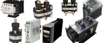
Various household appliances and electrical tools use a triac power regulator to regulate power.
Regulators for resistive loads
The current regulator circuit for the active load of thyristors assumes the use of a triode type. They are capable of transmitting signals in both directions. The anode current in the circuit is reduced by lowering the limiting frequency of the device. On average, this parameter fluctuates around 5 Hz. The maximum output voltage should be 5 V. For this purpose, resistors are used only of the field type. Additionally, conventional capacitors are used, which on average can withstand a resistance of 9 ohms.
Pulse zener diodes are not uncommon in such regulators. This is due to the fact that the amplitude of electromagnetic oscillations is quite large and needs to be dealt with. Otherwise, the temperature of the transistors quickly increases and they become unusable. To solve the problem with the falling pulse, a wide variety of converters are used. In this case, specialists can also use switches. They are installed in regulators behind field-effect transistors. However, they should not come into contact with the capacitors.
How to increase the current in the power supply?
On the Internet you can often come across the question of how to increase I in the power supply without changing the voltage. Let's look at the main options.
Situation No. 1.
A 12 Volt power supply operates with a current of 0.5 Amperes. How to raise I to its maximum value? To do this, a transistor is placed in parallel with the power supply. In addition, a resistor and stabilizer are installed at the input.
Find out more - how to check a transistor with a multimeter for serviceability.
When the voltage across the resistance drops to the required value, the transistor opens, and the rest of the current flows not through the stabilizer, but through the transistor.
The latter, by the way, must be selected according to the rated current and a radiator installed.
In addition, the following options are possible:
- Increase the power of all elements of the device. Install a stabilizer, a diode bridge and a higher power transformer.
- If there is current protection, reduce the value of the resistor in the control circuit.
Situation No. 2.
There is a power supply for U = 220-240 Volts (at the input), and at the output a constant U = 12 Volts and I = 5 Amperes. The task is to increase the current to 10 Amps. In this case, the power supply should remain approximately the same dimensions and not overheat.
Here, to increase the output power, it is necessary to use another transformer, which is converted to 12 Volts and 10 Amps. Otherwise, the product will have to be rewound yourself.
In the absence of the necessary experience, it is better not to take risks, because there is a high probability of a short circuit or burnout of expensive circuit elements.
The transformer will have to be replaced with a larger product, and the damper chain located on the DRAIN of the key will also have to be recalculated.
The next point is replacing the electrolytic capacitor, because when choosing a capacitance you need to focus on the power of the device. So, for 1 W of power there are 1-2 microfarads.
It is also recommended to change the diodes with rectifiers. In addition, it may be necessary to install a new rectifier diode on the low side and increase the capacitor capacity.
After such a modification, the device will heat up more, so installing a fan is not necessary.
How to make a phase model of a regulator?
You can make a phase current regulator with your own hands using a thyristor marked KU202. In this case, the supply of blocking voltage will proceed unhindered. Additionally, care should be taken to ensure the presence of capacitors with a maximum resistance of over 8 ohms. The fee for this case can be charged PP12. In this case, the control electrode will provide good conductivity. Pulse converters in regulators of this type are quite rare. This is due to the fact that the average frequency level in the system exceeds 4 Hz.
As a result, a strong voltage is applied to the thyristor, which provokes an increase in negative resistance. To solve this problem, some suggest using push-pull converters. The principle of their operation is based on voltage inversion. It is quite difficult to make a current regulator of this type at home. As a rule, it all comes down to finding the necessary converter.
Recommendations
If you do not have experience and knowledge of how to handle electrical appliances, then it is best not to touch them. If the wiring is incorrect, the network can receive a short circuit, as a result of which this device, as well as several others that were connected to the network, burned out.
Using the services of professionals significantly saves time and money, which you would still have to spend on a specialist if you did everything yourself. During the work, you can ask a professional about the manipulations being carried out.
He will tell you in detail what and how to connect and connect. Will share tips and tricks, conduct a practical lesson with devices.
Pulse regulator device
To make a pulse current regulator, the thyristor will need a triode type. It supplies control voltage at high speed. Problems with reverse conductivity in the device are solved using bipolar transistors. Capacitors in the system are installed only in pairs. A decrease in the anode current in the circuit occurs due to a change in the position of the thyristor.
The locking mechanism in regulators of this type is installed behind the resistors. To stabilize the limiting frequency, a wide variety of filters can be used. Subsequently, the negative resistance in the regulator should not exceed 9 ohms. In this case, this will allow it to withstand a large current load.
Resistor or inductance
Adjusting the welding current using a resistance or inductor is the simplest and most reliable. A powerful resistor or inductor is connected in series to the welding electrode holder. Due to this, the active or inductive resistance of the load changes, which leads to a voltage drop and a change in the welding current.
Regulators in the form of resistors are used to improve the current-voltage characteristics of the welding machine. A set of powerful wire resistances or one resistor made of thick nichrome wire in the form of a spiral is used.
To change the resistance, they are connected to a specific turn of wire using a special clamp. The resistor is made in the form of a spiral to reduce its size and ease of use. The resistor value should not exceed 1 ohm.
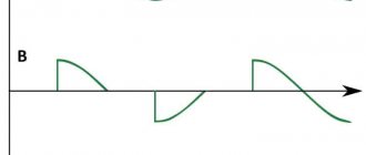
Alternating current at certain times has zero or close to it values. At this time, a short-term arc extinguishing occurs. When the gap between the electrode and the part changes, sticking or complete extinguishing may occur.
To soften the welding mode and, accordingly, obtain a high-quality seam, a regulator is used in the form of a choke, which is connected in series with the holder in the output circuit of the device.
The additional inductance causes a phase shift between the output current and voltage. At zero or close to zero values of alternating current, the voltage has a maximum amplitude and vice versa. This allows you to maintain a stable arc and ensures reliable ignition.
The choke can be made from an old transformer. Only its magnetic core is used, all windings are removed. Instead, 25-40 turns of thick copper wire are wound.
This regulator was widely used when using AC transformer devices due to its simplicity and availability of components. The disadvantages of the welding current throttle regulator are the small control range.
Soft start models
In order to design a thyristor current regulator with soft start, you need to take care of the modulator. Rotary analogues are considered to be the most popular today. However, they are quite different from each other. In this case, much depends on the board used in the device.
If we talk about modifications of the KU series, they work on the simplest regulators. They are not particularly reliable and do cause some glitches. The situation is different with regulators for transformers. There, as a rule, digital modifications are used. As a result, the level of signal distortion is significantly reduced.
Adjustment
It is worth understanding that the adjustment of the device does not depend on the shape of the input signal. Based on the type of placement, devices are divided into stationary and mobile.
- The differences are obvious, the first type is securely attached to a specific place.
- The second option, on the contrary, has the ability to be in any place where it is convenient for the master.
The voltage regulation device is currently an electrical circuit, thanks to which it becomes possible to regulate the voltage in a particular building if everything is connected correctly.