Electrical machines › DC electric machines
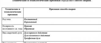
An element of the armature winding is a section , which at its ends is attached to two collector plates. Sections can be single-turn or multi-turn . The grooved sides of the sections are located in the grooves of the armature core. The distance between the groove sides of the section is approximately equal to the pole division.
where Da is the diameter of the armature core.
Usually the armature windings are made of two layers . Depending on the order in which the sections are connected to the collector plates, the windings are divided into wave and loop, simple, complex and combined.
Simple wave winding
In a simple wave winding, the ends of each section are connected to commutator plates located at a distance called the commutator winding pitch,
where K is the number of collector plates in the collector.
In Fig. Figure 13.5 shows a diagram of a simple armature wave winding. The winding sections form two parallel branches (2a = 2). The number of parallel branches in the winding and the number of sections in each branch determine the current Ia and EMF Ea of the armature winding:
where S is the number of sections in the armature winding; ec is the EMF of one section; Iс is the permissible current value in the section.
Contents Previous § Next
4.7. Armature windings of DC machines
4.7.1. Features of the design of armature windings
The armature windings of DC machines are two-layer, in machines with a power of up to 30 - 40 kW they are made of round wire, in machines of higher power or for special purposes - from rectangular winding wire. The main element of the winding is a section that consists of one or more turns. A winding with single-turn sections is called a core winding. The output ends of each section are connected to the collector plates. Since each collector plate is connected to the beginning of one and the end of the second section, the number of collector plates K
equal to the number of sections
S
in the armature winding.
Several sections, the groove sides of which are placed in one layer of the groove and have a common body insulation, form a winding coil. The coil has as many pairs of output ends as there are sections it consists of. Examples of filling armature slots with conductors (sectional sides) and winding insulation from round and rectangular wires are shown in Fig. 4.25.
Armature windings can be loop or wave, simple or complex.
IN)
Rice. 4.25. Examples of filling the armature slots of DC machines with conductors
windings and insulation:
A
— semi-oval semi-closed groove, round wire winding;
b - rectangular open slot, winding made of rectangular wire (np = 3, ws
= 2);
c -
rectangular open groove, rod winding
(ip =
3,
ws =
1);
/ - body insulation; 2
- winding conductors;
3 -
spacer between layers;
4
— gasket under the wedge;
5 — groove wedge, b —
wire bandage; 7 — gasket for the bandage;
8 —
gasket for the bottom of the groove
Rice. 4.26. Designations of armature winding steps:
A
- loop;
b -
wave
They are characterized by two partial steps, a step along the collector and along the grooves (Fig. 4.26). Partial steps (first yv
the second
ang
and the resulting
y)
are measured in the so-called elementary grooves and have no equivalent in linear dimensions.
By elementary we mean a conditional groove in which one sectional side is located in each layer. Hence the number of elementary grooves of the armature z3 = S
=
K = zun,
where
un is
the number of sections in the armature coil.
The step along the collector uk
is measured by the number of collector divisions and determines the distance between the beginning and end of the section along the circumference of the collector.
The distance between the sides of the coil in the slot divisions of the armature determines the pitch of the winding along the slots ang.
The step along the grooves and the first partial step are related by the ratio ug
=
y\/ish.
In most windings!
/and„
is an integer.
In this case, the winding is equal-sectional. If yt/u„
is not an integer, then the winding is stepped. Step windings are avoided whenever possible due to the technological difficulties of their implementation.
4.7.2. Armature loop windings
IN
simple loop windings
y
=
yk = = ±
1 and
U = U1-U2 -
Windings with y, = + 1 are more widespread (Fig. 4.27),
since when yk = -
1, the frontal parts of the sections are somewhat lengthened and additional crossing occurs in the frontal parts of the winding.
The first partial step of the loop winding is close to the pole division: y1 = = z3/2p ± %,
where
\ is
a fraction in which
y1 is
an integer.
The value £
characterizes the shortening (lengthening) of the pitch
yt
compared to the pole division. Windings with shortened pitches are more common.
The loop winding requires the installation of brushes through each pole division, i.e. on 2p brush bolts. In this case, 2p parallel branches are formed in the winding. Thus, in a simple loop winding, the number of parallel branches is always equal to the number of poles, i.e. 2a
=
2r.
The asymmetry of the EMF and the resistance of parallel branches causes the possibility of the occurrence of equalizing currents, overloading the brush contacts and worsening switching.
Therefore, in armatures with loop windings of machines with 2p>2,
equalizing connections of the first kind must be installed.
In Fig. Figure 4.27 conventionally shows only two equalizing connections. On machine anchors, several connections are usually installed for each pair of poles or one connection for each armature slot. In high-power machines with difficult commutation, each section of the armature winding is connected by an equalizing connection. Structurally, equalizing connections are located under the frontal parts of the armature winding on the commutator side or on the side opposite to the commutator (Fig. 4.28). The installation of equalizing connections leads to a complication of the manufacturing process and an increase in the cost of the machine, therefore loop winding is used only in those machines in which a simple wave winding cannot be performed.
In machines with large rated armature currents, a complex loop winding is used to increase the number of parallel branches. Number of parallel branches in a complex loop winding 2a
= 2pm, and the step along the collector
uk - t,
where
t
is the number of winding strokes.
Depending on the K/t
a complex loop winding can be short-circuited or m-short-circuited.
In complex loop windings, it is necessary to install equalizing connections not only of the first, but also of the second kind, connecting points of theoretically equal potential belonging to different simple windings combined into a complex one.
Rice. 4.27. Scheme of a simple armature loop winding, z=
14,
K
= 42,
ia =
3
Rice. 4.28. Examples of constructive implementation of equalizing connections of the first kind:
A
- fork on the collector side;
b -
fork on the side opposite to the collector;
c -
ring; G
— involute;
/ - collector plates; 2 —
bandage of equalizing connections;
3
—
equalizing connections; 4 —
frontal parts of the armature winding; 5 — winding holder
ii |i li |ih |i I! |i |i ii |i |i |i |ii li Ii Ii Ii Ii Ii Ii Ii Ii Ii Ii Ii Ii Ii Ii Ii Ii
/ 2 3 H 5 6 7 S 9 10 tl 12 IS 14 IS 16 17 18 19 20
19\20\1 \2\3\q\S\6\7 \v\9\10\11\12\13\Ш15\16\17\16
Rice. 4.29. Scheme of a two-pass loop winding of the armature at Kip,
equal to an even number (k = 20, 2р = 4), with equalizing connections
In double-closed two-pass (t = 2) loop windings at K/p,
equal to an even number, points of theoretically equal potential are located on different sides of the armature. In a simplified diagram of such a winding (Fig. 4.29), equalizing connections of the second type are shown to the left of the diagram. In such machines, equalizing connections of the second type must be passed under the armature magnetic wire along the shaft or through the bushing (Fig. 4.30).
With K/r,
equal to an odd number, in two-way doubly closed loops
12J
Rice. 4.30. Location of equalizer connections of the second type at anchor: 1
— collector;
2
- equalizing connections of the first kind;
3 -
armature winding;
4
— armature magnetic circuit;
5
- equalizing connections of the second kind
On the left windings, equalizing connections of the first kind simultaneously serve as equalizing connections of the second kind, since they connect sections of different simple windings (Fig. 4.31). In the figure shown, two sections connected by equalizer connections are highlighted with thick lines. The same applies to two-way single-closed loop windings, since they always have K/p
equal to an integer.
4.7.3. Armature wave windings
IN
in machines with a rated armature current of no more than 500-600 A, wave windings have become more widespread (Fig. 4.32).
In simple wave windings y = y^+yr
and
2a = 2
, regardless of the number of poles of the machine. The advantages of simple wave windings are the absence of equalizing connections and the ability to operate the machine with an incomplete number of brush bolts. The latter winding feature is used, for example, in a number of traction motors due to limited space to accommodate a full set of (2p) brush bolts.
18
|
1
|
2
|
3 | 4 \S
|
6- | 7 | 8\9
|
?g| 11
|
/^ 173 \14 \i5\16\n
Fig. 4.31. Scheme of a two-pass loop winding of an armature at K/r,
equal to an odd number
with equalizing connections
Rice. 4.32. Scheme of a simple wave armature winding, z = 17, K=
51,
And"
= 3
Rice. 4.33. Schemes of wave asymmetrical windings of armatures:
a-winding with a “dead” section, g = 18, K=P,
2/> = 4; b - artificially closed winding, z=18,
*=18, 2р = 4
The step along the collector of a simple wave winding (Fig. 4.32) is equal to uk = (K
+ 1)
/р
(with the “+” sign, the winding is obtained with intersecting frontal parts, so the “-” sign in the formula is the main one).
If yk
is not equal to an integer, then the winding cannot be made symmetrical. In individual machines, for example, in widespread machines with 2p = 4, with even z or even CP, an asymmetrical wave winding with a “dead” section is sometimes made (Fig. 4.33, a). The collector is like this
machine contains one plate less than the number of elementary slots or the number of all sections in the winding. When K >
100 asymmetry in such machines has practically no effect.
When uk,
not equal to an integer, it is also possible to use an artificially closed wave winding (Fig. 4.33, b), in which the number of sections is one more than the numbers
z3
and
K.
The section of this winding, for which there is “no place” in the armature slots, degenerates into a connecting conductor , closing co-
Rice. 4.34. Scheme and sequence of laying a two-chord armature winding, r = 9, 2р = 2,
K=9:
a - winding diagram;
b -
sequence of laying turns in the grooves of the armature
end of the last section with the beginning of the first section of the winding.
In special-purpose machines, complex wave windings with t >
1. For them,
yay.
= (K +
t)/2r.
The number of parallel branches of a complex wave winding
is 2a ~ 2t.
In them, as well as in complex loop windings, it is necessary to install equalizing connections of the second type.
In a number of medium-power machines, to reduce the current in parallel branches and to avoid the need to install equalizing connections, a combined, so-called frog winding is used, the coils of which consist of sections of wave and loop windings and sections of both loop and wave windings are connected to each collector plate.
Thus, in the grooves of the armature there are, as it were, two independent windings - wave and loop. The number of parallel branches of these windings must be the same, so the wave winding must be complex. The number of parallel branches of the frog winding is 2 times greater than the loop winding for this machine.
Equalizing connections in combined windings are not required, since the wave winding sections play the role of equalizing connections for the loop winding, and the loop sections act as equalizing connections for the complex wave winding. Thanks to this, frog winding has become widespread despite the technological complexity of manufacturing its coils.
Laying conventional two-layer armature windings cannot be mechanized due to the need to raise the pitch at the final stage of this operation. Therefore, in anchors intended for mechanized laying, slightly modified circuits are used, for example, a two-chord winding (Fig. 4.34).
Contents Previous § Next
Simple loop winding
In low voltage (significant current) DC machines, an armature winding with a large number of parallel branches is required. Loop windings have this property. In a simple armature loop winding (Fig. 13.7), each section is connected to two adjacent collector plates, and the number of parallel branches is equal to the number of poles, i.e. 2a = 2p.
Electric cars
Ministry of Education and Science of the Russian Federation
Omsk State Technical University
Department of “Theoretical and General Electrical Engineering”
Lecture notes
Electric cars
LECTURE: “Types of armature windings. EMF of the armature winding. Electromagnetic moment. ”
Omsk 2005
1. Classification of windings
The armature winding is an important element of a DC machine; an EMF is induced in it, the load current flows through it, and it determines the nominal values: voltage, current and power of the machine. Various designs of these windings are possible.
One type of armature winding is a ring winding, an example of which is the winding shown in Fig. 40.1. In such windings, the conductors located on the inner surface of the armature core do not participate in creating the EMF of the machine, which reduces the use of the winding wire. In order to make these conductors active, they should be placed on the outer surface of the armature under a pole of a different polarity. With this placement, each turn of the winding will consist of conductors located under poles of different polarities, and the EMF of the turn is equal to the sum of the EMF of these conductors, i.e. it will be 2 times greater than that of a ring winding. Windings in which all conductors are located on the outer surface of the armature are called drum windings.
Rice. 1. Transition from ring winding to drum winding
Modern DC machines have drum windings at the armature. The windings consist of sections that are laid in the armature slots in two layers: one side of the section is laid in the top layer of one slot, and the other in the bottom layer of another slot. If in each layer of the groove there is one side of the section, then such a groove is called elementary (Fig. 2). In real machines, most often in each layer there is not one, but u
P sectional sides, where
u
P = 2, 3, 4... We will consider such a real groove to consist of
u
P elementary ones.
For example, in Fig. 3 real groove consists of u
П = 3 elementary grooves.
Before laying in the groove, u
P sections are covered with general insulation, resulting in the formation of an armature winding coil.
Sections in the winding are connected to each other in a certain sequence. Depending on this, the windings of DC machines are divided into loop, wave and combined. Loop and wave windings, in turn, are divided into simple and complex (multi-pass). The number of its parallel branches will depend on the type of winding, which determines the scope of its application.
The sequence of connecting the sections to each other and to the collector plates is specified by winding steps. To do this you need to have the following steps (Fig. 4):
y1
- the first partial step, equal to the distance between the sides of the section. This step determines the width of the section. The side of the section lying in the upper part of the groove is called the initial side, and the other side lying in the lower part of the corresponding groove is called the final side;
y
2 - second partial step, equal to the distance between the end side of this section and the start side of the subsequent section to which it must be connected;
at
— the resulting step, equal to the distance between the beginnings of sections following each other according to the connection diagram;
| Rice. 2. Elementary groove | Rice. 3. Real groove, consisting of three elementary ( u P=3) | Rice. 4. Connection of loop winding sections |
y
K is the step along the collector, equal to the distance between the points of connection of the section conductors to the collector.
Winding pitches are measured in elementary slots, and the pitch along the commutator is measured in commutator divisions.
Step y
1 is chosen so that the beginning and end of the section are located under poles of different polarities, i.e., so that the width of the section is equal to the pole division.
Then, when the armature rotates, the EMF induced in the sides of the section will have opposite directions, and in the circuit of the section they will be summed up. Step y
1 must be equal to an integer, it is determined by the formula
where z
E is the number of elementary grooves;
p
—number of pole pairs;
ε
is a proper fraction in which
y
1 is equal to an integer (the value of k can be taken with a plus or a minus sign, most often
ε
is taken with a minus sign, since in this case the wire consumption per winding is reduced).
If it is an integer, then the winding pitch is called full or diametrical ( τ
n - polar division expressed in elementary grooves).
When the winding will have a shortened pitch. For all windings used in DC machines, step y
1 is determined by (1).
The values of other steps depend on the type of winding. If, for example, step 1
= 6, then this means that one side of the section lies in the first elementary groove, and its other side lies in the seventh.
The number of elementary slots zе number of sections S
and the number of collector plates K
in
DC machines are related to each other by certain relationships. Since each section has two sides and two sectional sides are also placed in the elementary groove, and conductors from two sectional sides approach the collector plate, then
Since conductors are connected to each collector plate from the end of this section and from the beginning of the next section according to the winding diagram, we can assume that y
K is the distance in commutator divisions between the beginnings of successive sections. Then we can assume that
When depicting windings, it is customary to use sweep diagrams. On the development, elementary grooves are applied in the form of two lines: solid (upper sectional side) and dashed (lower sectional side). To simplify drawing the circuit, it is usually assumed that the sections consist of one turn ( wS
=l).
Let's move on to a specific consideration of the various windings. In order not to complicate the drawing when constructing winding diagrams, the number of elementary slots and sections will be taken to be reduced compared to the number that is usually found in real machines.
2. Simple loop windings
A loop winding is obtained by connecting adjacent sections in series (Fig. 4). The winding got its name due to the fact that when sections of the winding are connected in series, they form a loop shape.
Let's build a sweep circuit for the loop winding at z
E=18 and
2p
=4. The winding steps will have the following values;
Let us number the elementary grooves in order and assume that the upper sectional side of the beginning of the section has the groove number, and the bottom side (end of the section) has the number of the groove with the line. Let's start connecting the conductors from the first groove.
The sequence of connecting the winding conductors can be represented as
In Fig. 5 a schematic diagram is constructed. The winding is connected to the collector. Two conductors approach each collector plate: from the end of one section and the beginning of the next according to the section connection diagram.
Rice. 5. Scheme of a simple loop winding with zе=S=K=18, 2р
=4
Let us agree to assign the collector plate the number of the section to which it is connected.
To place the brushes on the commutator, you need to know the location of the poles. Let us outline the contours of the poles in the figure, for which we arbitrarily divide the armature into 2p equal parts (in this case, four). We will take the dividing lines between the parts as geometric neutrals (GN). Then the distance between adjacent neutrals will be equal to the pole division τP
.
In the middle part of this division, at an equal distance from the neutrals, the poles are placed, which usually occupy (0.75-0.85) τP
.
The fingers with brushes on the commutator are placed in such a way that the brushes come into contact with the plates to which the sections located close to the neutrals are connected. With a symmetrical shape of the frontal parts, the brushes are geometrically located along the axis of the poles. However, in this case, they say that the brushes are installed on a geometric neutral, meaning that they come into contact with sections located in or near the neutral.
The number of brush fingers is taken equal to the number of poles. The brush fingers are placed at the same distance from each other. As can be seen from Fig. 5, some brushes will overlap two adjacent commutator plates and short-circuit the section connected to those plates. Such sections are called short-circuited or switched.
When the armature rotates, an emf will be induced in the conductors of its winding, the direction of which is shown in Fig. 5 arrows. The EMF in conductors located under adjacent poles has the opposite direction due to the different polarity of the poles. In short-circuited sections, EMF will not be induced, since the sides of these sections lie near the neutrals, where the magnetic field induction is practically zero. If the machine operates as a generator, then the direction of the current in the conductors coincides with the direction of the EMF.
As can be seen from Fig. 5, the emf between adjacent brushes is equal to the sum of the emf of the conductors connected between them, and the brushes have alternating polarity. Brushes of the same polarity are connected to each other, and a network is connected to their common points.
In relation to the terminals, the armature winding is divided into several parallel branches, the diagram of which is shown in Fig. 6. Comparing Fig. 6 from fig. 5 we find that each parallel branch includes sections whose beginnings are located under the same pole.
Rice. 6. Diagram of parallel branches of the winding shown in Fig. 5
Therefore, in the general case, the number of parallel branches of the winding is 2 a
(
a
- the number of pairs of parallel branches) is related to the number of poles 2p of the machine by the relation 2
a
= 2
p
This ratio is a characteristic feature of loop windings.
In this case, 2 p
=4, therefore 2
a
=4.
3. Complex loop windings
Complex loop windings are used to increase the number of parallel branches. They are a collection of m simple windings laid on the same armature. In this case 2 a
=2
r m
.
When forming a complex loop winding, they are connected in series not to adjacent sections, as was the case in the previous case, but to sections spaced from each other by m
elementary grooves, i.e.
y
= m.
Accordingly yK
=m.
The partial winding steps are:
Complex windings consisting of m simple ones are called m-running. The greatest practical application is found in windings at t
=2 (
y
=2,
y
K=2).
In this case, if z
E is an even number, the complex winding will consist of two identical independent windings, one of which will consist of sections, the beginnings of which will be located in odd slots, and the other of sections, the beginnings of which will be located in even slots.
Such a winding is called a complex two-way double-closed winding. Let's construct a sweep diagram of such a winding according to the following data: z
E = 18,
2p
= 4,
t
= 2. Winding steps: The diagram of this winding is shown in Fig. 7.
If the number of elementary slots is an odd number, then the complex winding will be a two-way, single-closed winding.
Rice. 7. Scan diagram of a complex loop winding with z e= S =
K =18
,
2 p
=4
When performing it, in the first bypass of the armature, sections are connected, the beginnings of which lie in odd slots, and then, without interrupting the winding, they perform a second bypass of the armature and connect sections whose beginnings lie in even slots. After the second bypass, the winding is closed with the original section. In general, if z E
and
y
have a common greatest divisor
q
, then the winding
q
-fold closed. If zE and y are mutually prime numbers, then the winding is single-closed.
4. Simple wave windings
In wave windings, sections are connected in series, the beginnings of which lie under successive poles of the same name (Fig. 8). With this connection, the resulting pitch is approximately equal to two pole divisions. After p
steps, the winding makes a wave-like circuit around the armature, and so that during the first circuit it does not short-circuit to the original section, it must approach an elementary groove located on the left or right next to the original one, i.e.
from where we find the resulting pitch of the wave winding:
Usually in (3) the unit is taken with a minus sign, since with this step the winding wire consumption is slightly reduced due to a decrease in the length of the end connections.
Rice. 8. Connection of wave winding sections
Since the number of sections is equal to the number of elementary grooves, S
=
z
E, then
In accordance with Fig. 8 y2=y—y1
, and the step along the collector
y K
=
y
.
Let's construct a sweep diagram of the wave winding using the following data: z
E=21,
K
=21,
2p
= 4. Find the steps:
y1
=5,
y
=10,
y
2=5,
yK
=10.
Connection diagram
The winding layout is shown in Fig. 9. The arrangement of brushes on the commutator is carried out in the same way as with loop windings - the brushes must be in contact with the plates to which the sections located on or near the neutral are connected.
Fig. 9. Scan diagram of a simple wave winding with z
E=21,
2p
= 4
For any number of poles, the number of parallel branches of the wave winding is equal to two. Using the example of the considered winding, it can be established that all sections, the beginnings of which are located on the pole divisions of south polarity, will be included in one parallel branch, and in the other - north polarity.
Since the wave winding has two parallel branches, the number of brush bolts in the machine can be reduced to two. The distribution of sections along parallel branches in this case remains practically the same as with a full set of brushes.
To perform a wave winding, it is necessary that the step y be equal to an integer. However, this cannot be achieved for any value of z
E
and
S. For example, according to (3) in a four-pole machine (p=2) with even values of z E
and S,
the step In such cases, it is necessary to use “dead” sections to perform the winding. “Dead” sections are those laid in the armature slots, but not connected to the winding circuit. They are left at the anchor so as not to disturb its mechanical balancing. Wave windings with a “dead” section are sometimes used in machines with a power of up to several tens of kilowatts. The production of such windings is associated with the desire to use the existing stamp of armature sheets for the manufacture of machines with a different number of poles.
5. Complex wave windings
Complex wave windings are used to increase the number of parallel branches. These windings are a combination of m simple windings laid on one armature. In this case 2a=2 m
.
When making such windings, after p
resulting steps around the armature, the conductor must approach not the one adjacent to the original groove, but the groove spaced from it by
t
elementary grooves.
The missing t 1 slots
This condition can be written as the equality
whence, taking into account the fact that z
E=
S
, follows
Step along the collector
K=
y
.
Second partial step y
2 =
y - y 1
.
Complex wave windings can be single-closed or multiple-closed.
6. Winding symmetry conditions
When designing windings, they strive to make them symmetrical. By symmetrical we mean an armature winding in which, for any moment in time, the EMF and the resistance of its parallel branches will be the same. If these conditions are not met, equalizing currents will flow through the winding and brushes, which can cause deterioration in the performance of the brush contact and an increase in losses in the armature.
The conditions for winding symmetry can be formulated based on the following reasoning. First of all, it is necessary that in each real groove of the armature there is the same number of sectional sides, i.e.
where z
— number of real grooves.
An electric machine with an armature winding having 2a
parallel branches can be represented as consisting of elementary machines connected in parallel, each of which has two parallel branches. In order for a elementary machines to be identical, each of them must have the same integer number of sections and collector plates:
For a symmetrical arrangement a
machines in a magnetic field is necessary
Relations (4) - (7) represent the conditions for symmetry of the windings.
Condition (7) is always satisfied in simple loop and wave windings, since for the first a=p
, and for the second a
1 .
In complex loop windings a=tr
, therefore, this condition is satisfied only at
m=2
, and in complex wave windings symmetry is possible at
2p/t
=
integer,
since for these windings a
m .
In some cases, some deviation from the symmetry conditions is possible.
7. Equalizing connections
To improve the operation of DC machines, equalizing connections are used in some types of armature windings. They are divided into equalizing connections of the first and second kind. Equalizing connections of the first kind are used for loop windings, and of the second kind - for all complex windings.
Equalizing connections of the first kind are used to weaken the influence of magnetic asymmetry on the operation of the machine. Since in a loop winding each parallel branch is located under a pair of corresponding poles, then in the presence of magnetic asymmetry arising due to unequal air gaps, inhomogeneity of steel, etc., the fluxes of different poles, and therefore the EMF of the parallel branches will be unequal. As a result, equalizing currents arise in the winding, which will be closed through the brushes of the same polarity and the conductor connecting them, causing additional losses and heating of the winding, and superimposed on the load current, will overload the brushes and cause them to spark.
To prevent these consequences, the winding is equipped with special equalizing connections or equalizers. Equalization connections are conductors that connect points inside the winding that theoretically have the same potential. These points belong to sections that are in the same conditions in the magnetic field, that is, they will be shifted relative to each other by two pole divisions
In the presence of such connections, equalizing currents are closed through them, bypassing the brushes and commutator. These currents will be variable.
In complex windings, parallel branches of different strokes are electrically connected to the external network through the same brushes. Since the contact resistance across the width of the brush may not be the same, this can lead to uneven distribution of the load current along the parallel branches of the winding. As a result, losses in the winding will increase and the voltage drop between adjacent commutator plates will increase, which can lead to sparking of the brushes. In order to obtain a uniform distribution of current along the parallel branches, regardless of the state of the brush contact, equalizing connections of the second type are made in complex windings, which connect points belonging to different winding strokes and theoretically having the same potential.
8. Selecting the type of armature winding
When choosing a winding type, a number of conflicting requirements must be taken into account. The most preferable are windings with a smaller number of conductors, since in this case the volume of required insulation and groove dimensions are reduced, the use of active materials is increased, and the labor intensity and cost of manufacturing the winding are reduced. The fewer number of parallel branches it has, the smaller the number of conductors in the winding will be.
However, according to the conditions of spark-free operation of the brush contact (switching) and manufacturability, the current of the parallel branch should not exceed 300-350 A. Therefore, with an increase in the power of the machine and its current, it is necessary to increase the number of parallel branches of the winding.
From a switching point of view, it is necessary that the average voltage between adjacent collector plates
where U
HOM - the rated voltage of the machine, V, did not exceed 20-25 V.
The number of collector plates increases with the number of parallel branches of the winding, therefore, to reduce UK , CP
In some cases it is necessary to choose a winding with a large number of parallel branches. When increasing the number of collector plates, it should be borne in mind that, according to technological capabilities, the width of the collector plate should not be less than 3-4 mm.
Taking into account the stated requirements, the following recommendations can be made for the selection of armature windings of a DC machine:
1. In two-pole machines, a simple loop winding should be used (2a = 2)
.
2. In multi-pole machines with armature current I
≤700 A, a simple wave winding
(2a=2)
.
3. In multi-pole machines with armature current I
>700A loop winding should be used
(2a=2p)
.
If in the latter case the number of collector plates is too large, then a complex wave winding is used (2a = 2t)
. Complex loop windings and frog windings are used in large DC machines when, with a simple loop winding, the current in the parallel branch will exceed 300-350 A or the voltage between adjacent collector plates will be unacceptably high.
9. EMF of the armature winding
When the armature rotates in the magnetic field of the poles, an EMF will be induced in the conductors of the armature winding. The distribution of magnetic field induction in the air gap between the armature and the pole when the machine is idling (when the armature current is zero) is shown in Fig. 1. EMF induced in conductors having an active length l
δ and rotating with peripheral speed
υ
a, will be equal to:
where Вδх
—induction at a given point of pole division.
As noted, the emf between brushes of opposite polarity of machine E
is equal to the emf of one parallel branch.
The parallel branch includes N /2a conductors
(
N
is the total number of active armature conductors).
Then, assuming that the winding has a diametric pitch ( y
1=
τП
), we obtain
Rice. 10. Field pattern in the air gap of a DC machine at idle
Let us replace curve 1 (Fig. 10) of the induction distribution with straight line 2, parallel to the abscissa and having ordinate B
CP.
The value of B
CP is determined based on the equality of flows, which will be proportional to the areas of the figures bounded by curve 1 and line 2. Then we can write
If you imagine
and take into account that the pole flux, then
or
here n
— armature rotation speed, rpm;
Da
—outer diameter of the anchor, m; — pole division, m; is the structural constant of the machine.
Formula for EMF E
can be represented in a different form, for which we multiply the right side of (42.2) and divide by 2π, then
where is the angular velocity of the anchor; .
From (42.3) and (42.4). it follows that the armature emf E
is proportional to the rotational speed (or angular velocity), the main flow and does not depend on the shape of the induction distribution in the air gap of the machine.
Under the flow F
in (42.2) - (42.4) we should understand the flow coupled with the section when it is symmetrically located relative to the pole.
With a shortened step ( y 1 < τ П
), the flux coupled to the section decreases (it is proportional to the shaded area in Fig. 42.2), according to which the emf
E
. However, with the actually applied step shortening in the windings of DC machines, the reduction in EMF is insignificant, and therefore, when determining it, formulas (42) are also used
10. Electromagnetic torque
When the machine is loaded, current flows through the conductors of the armature winding ( Ia
- armature circuit current). When this current interacts with a magnetic field, an electromagnetic force arises, which for one conductor of the winding is equal to:
We will assume that the induction Bδx
retains its value along the entire active length of the conductor.
fx
force creates torque
All N
conductors of the armature winding will create an electromagnetic torque
Since the length l δ
of all conductors is the same and the same current
i
a flows through them, then
If we accept, as before, that the induction at all points of polar division τ
is equal to:
then we get
Substituting (42.7) into (42.5), and also taking into account (42.6), in final form we obtain
From (42.8) it follows that the electromagnetic torque of a DC machine will be proportional to the magnetic flux and armature current.
With a constant direction of rotation of the armature, the direction of the moment depends on the operating mode of the machine. When the machine operates in generator mode, the EMF induced in the armature winding will be greater than the voltage at the machine terminals, therefore the current in the armature circuit has the same direction as the EMF.
11. Test questions and homework.
| № | Content | Literature |
| 1 | ||
| 2 | ||
| 3 | ||
| 4 | ||
| 5 | ||
| 6 | ||
| 7 | ||
| 8 | ||
| 9 | ||
| 10 |
12. Literature
1. Tokarev machines. – M.: Energoatomizdat, 1990, 624 p.
2. Kopylov machines - M.: Logos, 2000, 607 p.
3. Woldek machines. – L.: Energy, 1978. – 832 p.
Complex loop winding
If it is necessary to obtain an even larger number of parallel branches, a complex armature loop winding is used (Fig. 13.8). Such a winding contains two simple loop windings (m = 2), so the number of parallel branches is doubled , i.e. 2a = 2 * 2p = 4p . Such windings are necessary in machines of significant power at low network voltage: 12; 24; 48 V.
In order for the distribution of currents in the parallel branches of the armature winding to be the same, it is necessary that the electrical resistance of these branches does not differ from each other and that the emf induced in the sections that make up each parallel branch are the same. If these conditions are not met, equalizing currents appear between the parallel branches, disrupting the operation of the brush-collector contact.
The exception is a simple wave winding , the sections of which are evenly distributed under all poles of the machine, so the magnetic unsymmetry of the machine does not cause equalizing currents to appear in this winding. As for simple loop and all types of complex armature windings, there are always reasons for the appearance of equalizing currents in them. This leads to the need to use so-called equalizing connections in these windings, through which equalizing currents are closed, relieving the brush-collector contact from overload. Equalizing connections complicate the manufacture of the armature winding and lead to additional consumption of winding copper.
§28. Armature windings
The principle of connecting individual conductors into a winding.
Modern DC machines use drum armatures, in which the winding conductors are placed in grooves on the outer surface of the cylindrical armature.
When making the winding, the conductors located in the grooves of the armature should be connected in such a way that e. d.s. formed in them. To do this, the two conductors forming a turn of the winding must be connected as shown in Fig. 92, a, that is, conductor A, located under the north pole, must be connected to conductor B, located under the south pole.
Rice. 92. The principle of winding a drum armature
The distance between the conductors making up the turn must be equal to or slightly different from the pole division m - the distance between the axes of adjacent poles. Under this condition, the turn will cover the entire magnetic flux of the pole and e. d.s arising in it when the armature rotates will have the greatest value.
For a visual representation of the windings, the cylindrical surface of the armature together with the winding is unfolded into a plane and all conductor connections are depicted as straight lines on the drawing plane (Fig. 92b).
The armature winding consists of separate sections. A section is the part of the winding located between two collector plates, following one after the other along the winding. The number of sections S in the winding is equal to the number of collector plates K. A section can consist of one or several turns connected in series. In the first case, the sections are called single-turn (Fig. 93, a, see Fig. 85, b), in the second - multi-turn (Fig. 93, b, see Fig. 85, a).
Rice. 93. Schemes of single-turn (a) and multi-turn (b) sections: 1 - active conductors; 2 — frontal part; 3 - active side; 4 - collector plates
Single-turn sections consist of two active conductors that directly cross the magnetic flux; active conductors are located in the grooves of the armature and are connected by frontal parts lying outside the armature core. Frontal parts in induced e. d.s. practically do not participate.
Multi-turn sections consist of two active sides, each of which combines several active conductors. Some high-power machines use anchor coils made of split sections (see Fig. 85, in §27). The armature winding, consisting of such sections, is called a rod winding.
In some cases, for design reasons and to reduce power losses in the armature winding, when manufacturing sections, instead of one solid conductor of the required cross-section, several conductors of a smaller cross-section are taken. These conductors are usually placed in a slot on top of each other and connected to the same collector plates.
All winding sections usually have the same number of turns. In winding diagrams, sections are always depicted as single-turn for simplicity. The winding section is placed in the grooves so that one of its active sides is in the top layer, and the other is in the bottom. In the diagrams, the sides of the sections located in the upper layer are shown with solid lines, and those in the lower layer with dashed lines.
When combining several sections into an anchor coil, each side of the anchor coil is in most cases placed in one common groove. In order for e. d.s, induced in individual sections, were added up; when connecting them, they are guided by the same rule as when connecting conductors into turns: the distance between the connected parts of the sections should be approximately equal to the distance between the axes of the poles.
Armature windings are divided into two main groups: loop (parallel) and wave (series).
Simple wave winding.
With a simple wave winding, sections lying under different poles are connected in series (Fig. 94).
Rice. 94. General view of the wave winding (a) and connection diagram of its sections (b)
In this case, after one round of the armature circle, i.e., after a sequential connection of p sections, they come to the collector plate located next to the original one.
For example, the beginning of section 1 is connected to the collector plate KP1, and its end is connected to the collector plate KP10 and the beginning of section 2, which is located under the next pair of poles; then the end of section 2 is connected to the other collector plate and to the beginning of the next section. After completing a full circuit of the armature circle, the end of the corresponding section is connected to the collector plate KP2 and the beginning of section 3, then in the same way with the collector plate KP11 and section 4, etc. until the winding is closed, i.e. will come to the beginning of section 1.
The anchor coil in the wave winding has the shape of a wave (Fig. 95, a), which is where it got its name.
Rice. 95. Shape of anchor coils with wave (a) and loop (b) windings: 1, 4 - groove parts (upper and lower sides); 2, 5 — rear and front frontal parts; 3 - rear head; 6 - ends of sections soldered to the collector
To make a winding, you need to know its resulting step y (see Fig. 94, b), the first y1 and second y2 partial steps, as well as the step along the collector uk. These steps are usually expressed in the number of sections passed (the step along the collector is expressed in the same units, since the number of collector plates is equal to the number of sections).
In a simple wave winding, the number of parallel branches of winding 2a is always equal to two and does not depend on the number of poles:
2a = 2 (56)
In Fig. 96, and as an example, a diagram of a simple wave winding of the armature of a four-pole machine having 19 sections, unfolded in a plane, is given, and in Fig. 96, b - equivalent diagram of this winding, showing the sequence of connecting its sections and the resulting parallel branches. The numbers 1, 2, 3, etc. indicate active conductors lying in the upper layer of each slot, and 1′, 2′, 3′, etc., in the lower layer.
Rice. 96. Schemes of a simple wave winding of a four-pole machine
With wave winding, only two brush fingers can be installed in the machine. However, this is done only in low-power machines; in more powerful machines, a full set (2p) of brush fingers is usually installed to reduce the current density under the brushes and improve current collection.
Simple loop winding.
With a simple loop winding, each section is connected to adjacent collector plates (Fig. 97).
Rice. 97. General view of the loop winding (a) and connection diagram of its sections (b)
For example, the beginning of the 1st section is connected to the collector plate KP1, and its end is connected to the adjacent collector plate KP2 and the beginning of the adjacent 2nd section. Next, the end of the 2nd section is connected to the next collector plate and to the beginning of the adjacent section, etc. until the winding is closed, i.e., until they come to the beginning of the 1st section. In this winding, each subsequent section is located next to the previous one, and the armature coil has the shape of a loop (Fig. 95, b), which is where the winding gets its name.
In a simple loop winding, the sections located under each pair of poles form two parallel branches, so the number of parallel branches throughout the entire winding 2a is equal to the number of poles 2p:
2a = 2p (56′)
Condition 2a = 2p expresses the main property of a simple loop winding: the greater the number of poles, the more parallel branches the winding has, therefore, the more brush fingers there should be in the machine.
In Fig. 98, and as an example, a diagram of a simple loop winding of the armature of a four-pole machine having 24 sections, unfolded in a plane, is given, and in Fig. 98, b - equivalent diagram of this winding, showing the sequence of connecting its sections and the resulting parallel branches (the designation of conductors and collector plates is the same as in Fig. 96).
Rice. 98. Schemes of the loop winding of a four-pole machine (UR - equalizing connections)
Application of loop and wave windings.
Each of the windings - loop and wave - has its own advantages. With the same number of conductors in the armature winding and the same number of poles, a simple loop winding will have p times more parallel branches than a wave winding. Consequently, it can pass a significantly larger current Iа = 2aiа than the wave winding (here Iа is the current in the parallel branch) (Fig. 99).
Rice. 99. Diagrams of parallel branches in a four-pole machine with loop (a) and wave (b) windings: 1 - collector plates; 2 - winding sections
The number of turns in each parallel branch with a loop winding is p times less than with a wave winding. Since the voltage of the machine is determined by the number of turns connected in series in each parallel branch, in a machine with a loop winding the voltage will be p times less than with a wave winding.
From the above it follows that in machines designed to operate at high voltages, it is advisable to use a wave winding. Such a winding is available in most auxiliary machines of electric locomotives and electric trains, which are designed to operate at a voltage of 1500-3000 V, and in some traction motors of electric trains.
In machines designed to operate at high currents, it is advisable to use a loop winding. Traction motors of electric and diesel locomotives, as well as electric locomotive excitation generators used for recuperation, have such a winding. Low power DC machines are usually made with two poles. With two poles, the loop and wave windings do not differ.
Equalizing connections.
In a simple loop winding e. d.s, induced in each parallel branch, is created by the magnetic flux of a certain pair of poles. E.m.f. E induced in all parallel branches of the winding should theoretically be equal (Fig. 100, a).
Rice. 100. E.m.f. induced in parallel branches of the armature winding with equality (a) and inequality (b) of the magnetic fluxes of individual poles
However, practically due to technological tolerances in the value of the air gap under different poles, casting defects in the core and other reasons, the magnetic fluxes of individual poles are somewhat different, as a result of which unequal e.m. operate in parallel branches. d.s.
If two parallel connected sources have unequal e.g. d.s. (Fig. 101), then some additional current will flow through the circuit formed by the two sources, due to the difference in e. d.s. E1-E2 sources.
Rice. 101. Occurrence of equalizing current with inequality e. d.s. two sources
This current is called equalizing current. The equalizing current Iur circulates inside the sources, does not do any useful work, but creates only losses of electrical energy in both sources. It causes uneven loading of individual sources, overloading the source with higher e. d.s. and unloading the source with less e. d.s.
In DC machines with inequality e. d.s. in separate parallel branches, the resulting equalizing currents will overload the brushes and impair the operation of the machines.
For example, with inequality e. d.s. E1 and E2 in the parallel branches of the armature winding 3 (Fig. 100, b) an equalizing current Iur will pass through the winding and through brushes 1 (A - D). The difference between e. d.s. E1 and E2 is 3-5%, but due to the small resistance of the armature winding, this is enough for quite significant equalizing currents to pass through the parallel branches, which contribute to the occurrence of sparking under the brushes.
In order for equalizing currents to be closed in addition to the brushes, equalizing connections are provided in the loop windings, which connect winding points that have theoretically equal potentials. Such points are the beginnings and ends of the armature winding conductors, located one from the other at a distance equal to double pole division 2t. The ideal would be to connect all such winding points. However, a large number of equalizing connections greatly increases the cost of the winding, so it is practically sufficient to have one or two equalizing connections for each group of sections lying in the same armature slot.
From a production point of view, it is convenient to connect equalizing connections to collector plates 2 (see Fig. 100, b). Usually they connect every third to fifth collector plate (Fig. 102).
Rice. 102. Scheme of making equalizing connections I, II, III in the loop winding.
The cross-sectional area of the wires used to make equalizing connections is 3-5 times less than the cross-sectional area of the armature winding conductors. Equalizing connections are most often located under the frontal parts of the armature winding next to the collector; in this case, they are outside the magnetic field of the main poles and no emission is induced in them. d.s.
Complex windings.
When the machine power is more than 1000 kW, complex multi-pass armature windings are used, which are several simple loop or wave windings wound on a common armature, offset relative to each other and connected to one collector. The use of multi-pass windings makes it possible to increase the number of parallel branches with a constant number of poles, an increase in which in some cases is impossible. However, these windings require complex equalization connections.
One type of complex winding is the parallel-series winding, used in some traction generators. It is a combination of simple loop 1 (Fig. 103, a) and multi-pass wave 2 windings.
Rice. 103. Diagram of a parallel-series winding (a), the location of its conductors in the grooves (b) and the shape of the armature coil (c)
Both windings are laid in the same slots and have common collector plates. For equality e. d.s. parallel branches formed by the loop and wave windings, the number of parallel branches of these windings must be the same.
The parallel-series winding is made in four layers (Fig. 103, b), since two two-layer windings are placed in the armature slots. This winding was called “frog” because of the shape of its anchor coil (Fig. 103, c). The winding in question does not require equalizing connections, which distinguishes it from other windings. The ability to reduce the voltage acting between adjacent collector plates by half compared to simple windings is an important advantage of parallel-series winding.
Combined winding
In electrical machines with a significant current in the armature winding, simple wave windings are not applicable, since in these windings the number of parallel branches cannot be more than two . To increase the number of parallel branches and avoid the undesirable use of equalizing connections in machines with high current loads, use a combined winding . Such a winding consists of sections of wave and loop windings, and the number of parallel branches in it is equal to the sum of the parallel branches of the loop and wave windings
.
It is necessary that the number of parallel branches of the wave winding be equal to the number of branches of the loop winding . Therefore, in a four-pole machine, the combined winding is made of simple loop (2a = 2p = 4) and complex wave (m = 2) windings. In this case, the number of parallel branches of the combined winding is 2comb = 4 + 4 = 8. In such a winding, the branches of one of the component windings serve as equalizing connections for the other. As a result, a combined winding with such a number of parallel branches turns out to be simpler than a complex loop winding.
Theory of armature windings of DC machines
The armature winding is a closed system of insulated conductors that ensures the required EMF and the passage of a given current. In modern DC machines, two-layer drum armature windings are mainly used. In accordance with the purpose of the machine, a number of requirements are imposed on the windings. The winding must have the lowest possible copper consumption while ensuring the highest possible EMF and efficiency, be as symmetrical as possible, and have sufficient electrical, thermal and mechanical strength. The winding consists of individual turns and sections. A turn is two conductors connected in series. Several turns connected in series form a section. Sections can be single-turn or multi-turn, Figure 1.1.
The section has two active sides located in the grooves of the armature under the opposite poles of the machine, with the left active side placed in the upper layer of the groove, and the right one in the lower layer. As a result, the electromotive forces of the active sides of the section are added, and the winding turns out to be two-layer. The end of one section is connected to the beginning of the next section and at the same time to the collector plate, as a result of which all sections of the winding are connected in series and form a closed circuit. The active sides make up the groove part of section 1, and those parts that serve to connect the active sides with each other and with the collector plates are called frontal parts 2. The ends of sections 3,4 can be brought together (see Fig. 1.1, a) or separated (see Fig. 1.1, b).To obtain the highest EMF value, the distance between the active sides of the section, called the first partial winding step, must be equal to the pole division. The upper active side of one section and the lower active side of the other section located underneath it form an elementary groove. Since each section consists of two active sides, and the ends of two sections are attached to each collector plate, then in the armature winding the number of sections S is equal to the number of elementary grooves and the number of collector plates K
In a real armature groove there can be several elementary ones, therefore the number of real grooves Z is less than the number of elementary ones and is equal to
The distances between the active sides of the sections are measured by the number of elementary grooves. Since the width of the sections should be approximately equal to the pole division, the first partial pitch of the winding is determined by the expression
where 2p is the number of poles. Since it is not always an integer, the first partial step is rounded to the nearest integer, i.e.
Here is a fraction at which it becomes an integer. If the pole division is also measured by the number of elementary slots, then the formula for determining it will have the form
The first partial step at is called full or diametrical; if then the first step is called shortened; in this case the first step is called shortened; when - the step is elongated. The winding with a full step has the highest EMF. Shortening or lengthening the first partial step leads to a decrease in the EMF, since at any moment of time the active sides of the sections will be in unequal magnetic conditions. For a more visual representation of the winding diagram, the cylindrical surface of the armature, together with the winding, collector and poles, is conventionally cut along the axis of the machine and unfolded in plane, and all connections in the diagram are represented by straight lines. In this case, the diameter of the collector is taken to be equal to the diameter of the armature, and the poles are considered to be located above the plane of the drawing. The grooves are drawn not real, but elementary. Sections are considered single-turn
A winding circuit made in this form is called expanded. When depicting the winding diagram, the serial numbers of the collector plate, the section connected to this collector plate with the left active side, and the elementary groove, in the upper part of which the left active side of this section is located, are assumed to be the same.
According to the connection method and appearance of the winding sections, they are divided into:
• loop;
• wave;
• combined.
A simple loop winding is such a winding, the ends of each section of which are connected to two adjacent collector plates (Fig. 1.2.). In this case, the winding can be right-handed with non-crossing frontal parts (see Fig. 1.2, a) or left-handed with intersecting frontal parts (see Fig. 1.2, b). To implement an expanded winding circuit, it is necessary to determine its steps.
The primary partial step is determined by the formula
The resulting pitch of a simple winding y, which is the distance between the same active sides of two sections following each other according to the winding diagram, is equal to (+) for a right-hand winding, and the sign (-) for a left-hand winding.
The second partial winding pitch is the distance between the right active side of the section and the left active side of the section that follows the winding diagram. It is equal to The step along the collector for a simple loop winding is equal to
From this it is clear that
With the help of brushes, the armature winding is divided into parallel branches. For a simple loop winding, each parallel branch, enclosed between adjacent brushes of different polarities, corresponds to one pole division, therefore the number of parallel branches 2a is equal to the number of poles:
At this link you will find a complete course of lectures on mathematics:
| Solving problems in mathematics |
A complex loop winding consists of m simple loop windings. In such a winding, between two sections of each simple winding, space must be provided for m-1 sections of other simple windings that make up the complex winding (Fig. 1.3). Therefore, the resulting step y and the step along the collector of a complex winding must be equal
The remaining steps are determined accordingly by the formulas:
The number of parallel branches of a complex loop winding is
Here m is the winding factor.
A simple wave winding is obtained by connecting sections in series, located under different pairs of poles. The connection points of the sections are soldered to the collector plates. For each round, p sections are laid (Fig. 1.4.).
Each subsequent bypass begins with a collector plate located next to the starting plate of the previous bypass. If the repeated bypass begins with a plate located to the left of the original one, then the winding turns out to be left-handed with non-crossing frontal parts (Fig. 1.4, a). Otherwise - right-hand drive with intersecting frontal parts (Fig. 1.4, b).
In accordance with this, the step along the collector and the resulting step will be equal
where the sign (-) is for the left-hand winding, and the sign (+) is for the right-hand winding. The first partial step is determined by the usual formula
The second partial step is determined by the formula
Since the circuit of a simple wave winding passes through all the pole divisions in one round around the armature, the number of parallel branches of the winding 2a is always equal to two: 2a = 2.
A complex wave winding consists of m simple wave windings, therefore, the number of parallel branches for it is 2a = 2m.
According to the above, the steps of a complex winding can be determined using the expressions:
Complex windings can be single or multiple closed. In the latter case, the simple windings that make up the complex winding do not have electrical connections with each other other than brushes and equalizing connections, that is, each simple winding is closed on itself. In complex windings, each simple winding must have contact with the brushes, therefore the width of the brushes must be at least m collector divisions.
The combined winding is a combination of simple loop and complex wave windings, which are laid in the same armature slots in four layers and connected to the plates of the same collector (Fig. 1.5.)
For symmetry, both windings consist of the same number of sections, and each of them serves to carry half of the total armature current. In this regard, the number of parallel branches of a simple loop winding must be the same as the number of parallel branches of a complex wave winding
and in total the combined winding has the number of parallel branches
Conditions of symmetry. Each parallel branch of any armature winding can be conventionally represented as an elementary source of EMF E with internal resistance R. In this case, the equivalent circuit of the winding can be presented in the form of 2a parallel-connected sources.
| For normal operation of the machine |
it is necessary that the load current is distributed equally between the parallel branches. This is possible only if the EMF of all parallel branches and internal resistances are equal. For the EMF to be equal, it is necessary that each pair of parallel branches be located symmetrically in the magnetic field, that is, the following conditions must be met:
For equality of internal resistance and EMF, it is necessary that each pair of parallel branches contain the same number of sections
Equalizing connections. In DC machines, it is impossible to accurately satisfy all symmetry conditions, so equalizing currents arise in the windings, which close through the commutator and brushes and worsen their operating conditions. To relieve the brush contact from equalizing currents, equalizing connections are used to connect the terminals of winding sections that have theoretically the same potentials.
Equalizers of the first kind are used in simple loop windings, each pair of parallel branches of which is located under a separate pair of poles. If for some reason (unevenness of the air gap under the poles, shells in the frame, etc.) the magnetic flux of one pair of poles is not equal to the magnetic flux of the other pair of poles, then unequal EMFs will be induced in the corresponding parallel branches, as a result of which equalizing currents.
If there are equalizers of the first kind, these currents are closed through them, bypassing the brushes. Equalizers of the first kind equalize the magnetic asymmetry of the machine. They are usually located under the frontal parts of the armature winding on the commutator side and connect points of theoretically equal potential. The pitch of the equalizing connections must be equal to double the pole pitch
In a simple loop winding, the number of points of theoretically equal potential is equal to the number of pairs of parallel branches, so the total number of equalizers is equal. In simple wave windings, sections of parallel winding branches are located in series under all poles of the machine, so magnetic asymmetry does not appear in them and equalizing connections are not needed in them.
Equalizers of the second type are used in complex loop and wave windings. Complex windings consist of m simple windings, which are connected in parallel through a brush apparatus. Due to inequality in the resistance of brush contacts or parallel branches in such windings, electrical asymmetry may occur, which will cause equalizing currents between simple windings. These currents also close through the brush apparatus and impair its performance. Equalizers of the second kind connect such points of simple windings that make up a complex winding, which should have theoretically equal potentials. In this case, the step of the equalizing connection of the second kind is equal to
In combined windings, sections of the wave winding connect practically equal-potential points of a simple loop winding and act as equalizers of the first kind. Sections of a simple loop winding connect practically equipotential points of two simple wave windings, so they are essentially equalizers of the second kind. This is one of the advantages of combined windings.
Star and polygon EMF. Neglecting higher harmonics, we can assume that the induction in the gap under the poles is distributed sinusoidally. If the machine has 2p poles, then p sinusoids are placed around the armature circumference, each of which corresponds to 2 radians or 360 degrees. Thus, the armature circumference corresponding to 360 geometric degrees contains p360 electrical degrees. In other words, one geometric degree corresponds to p electrical degrees. In the future, we will express all angles only in electrical degrees. When the armature rotates in a sinusoidal field, an EMF is induced in the conductors of the armature winding, which also varies sinusoidally with time. Such EMF can be represented by vectors equal in magnitude to the amplitude of the EMF and rotating counterclockwise with an angular frequency. The projection of the EMF vector onto the ordinate axis gives the instantaneous value of the EMF. Since the conductors and winding sections are distributed evenly around the armature circumference, each section is offset relative to the adjacent one by an angle
You might find these pages useful:
| Gear calculation examples |
| Finding the original from an image |
| Corrosion of metals and alloys |
| Permissible stress strength condition |
The EMF vectors of the active sides of the sections will also be shifted by the same angle relative to each other. When it is assumed that all active sides of the sections of one real groove occupy the same position in the magnetic field and their emfs are in phase. The EMF vectors of all active sides form a star, called the slot EMF star. Individual star vectors can coincide: these are the EMF vectors of the active sides of one real groove and the EMF vectors of real grooves, shifted in the magnetic field by 360 el. hail Based on the star of the slot EMF, you can construct a star of the EMF of the sections. Due to the fact that the active sides of the section are connected by ends (Figure 1.6, a), the EMF vector of the section is obtained by geometrically subtracting the EMF vectors of its active sides. In the side (Fig. 1.6, a), located under the pole axis, the largest EMF is induced, directed upward. Let us depict it as a vector coinciding with the positive direction of the ordinate axis (Figure 1.6, b). In the second side of the section, an EMF is induced, directed downward along the contour of the section. It can be represented by a vector. With a diametrical step, the vector would lag behind the vector by 180 el. hail When the step lengthening is in this case half of the groove division, therefore, the angle between the vectors and is equal to el. hail To determine the EMF vector of section 1, it is necessary to add to the EMF vector of the left side the EMF of the right side of the section, rotated by the vector. If the section step were shortened, then the angle between the vectors would be el. hail (Fig. 1.6, c).From Fig. 1.6. it can be seen that with an extended and shortened step, the value of the EMF of the section is less than the maximum possible value, equal to twice the value of the EMF of the section side. For a given direction of rotation of the armature counterclockwise, section 1 is followed by section 2, then section 3 and so on with a shift by the slot angle. Consequently, the EMF vectors of sections 2,3 and so on can be represented by vectors shifted relative to the EMF vector of section 1 by an angle ; 2 and so on against the direction of rotation (Fig. 1.6, a).
The EMF vectors of the sections located under one pair of poles form a regular star. If there are p pairs of poles in the machine, you can get p EMF stars superimposed on the first one, or shifted relative to it by a certain angle, a multiple of . All sections of the armature winding are connected to each other in series so that the beginning of the next is connected to the end of the previous section. In this case, by geometrically adding the EMF vectors of the sections in accordance with the winding diagram, one or more EMF polygons can be obtained from the EMF star.
If the number of parallel branches of the winding is 2a = 2 (simple wave winding), then there will be one polygon. When 2a = 2p (simple loop winding) the polygons will be p and so on. The polygons rotate with the same angular frequency as the EMF vectors of the sections. Analysis of polygons allows us to draw a number of conclusions regarding the quality of the armature winding. In particular, you can determine the voltage between the collector plates and equipotential points, check the symmetry of the winding and the correct installation of the brushes, voltage ripple on the brushes, and so on...
Self-test questions:
1. What is the armature winding of a DC machine?
2. The purpose of the armature winding and the requirements for it.
3. Define the armature winding section and name its constituent elements.
4. Indicate the types of windings used in DC machines.
5. In what positions relative to the poles in the conductor of a rotating armature when the machine is idling is the maximum emf and emf equal to zero induced?
6. From what considerations is the width of the armature winding section selected?
7. What is an elementary groove and how does it differ from a real groove?
8. Define the steps of the armature winding (y1; y2; y; uk).
9. How are the expanded and simplified winding circuits performed?
10. How are brushes installed on the commutator of a DC machine?
11. How is the polarity of the brushes determined?
12. What is a parallel branch of the armature winding?
13. What is the EMF of the parallel branch and the machine as a whole?
14. How will the emf of the generator change if the brushes are moved in the direction (against the direction) of rotation by 1-2 commutator divisions?
15. Name the conditions for symmetry of windings.
16. How is a star and a polygon of EMF sections constructed?
17. What allows you to determine the EMF polygon?
18. Indicate the types of equalizing connections.
19. In which windings are equalizing connections used?
20. Why are equalizing connections not needed in simple wave windings?
21. From what considerations is the type of armature winding selected when designing a machine?
Turn-to-turn short circuits
This type of short circuit is a connection of turns inside the winding due to damage to the insulation of the winding wires. Most often, interturn short circuits occur when the insulation of the conductors is damaged during straightening and upsetting of the coils, when laying the winding, due to solder or shavings getting between the turns, when the winding breaks down on the housing, due to the crossing of wires in the groove part during random winding, etc.
Interturn short circuits can occur in one or more sections of the armature or between sections due to the short circuit of adjacent commutator plates. When there is a short circuit between the ends of a section or between the collector plates, as well as when individual turns of a section are connected to each other, closed circuits are formed in the armature winding.
In a loop winding, a short circuit between two adjacent plates causes a short circuit only in the section that is connected to these plates, and the number of turns operating in the winding is reduced by the number of turns contained in one section.
In a wave winding, a short circuit between two adjacent plates causes a short circuit in a number of sections that are contained in one complete circuit around the armature. Their number is equal to the number of pairs of poles of the machine.
In short-circuited circuits, when they rotate in a magnetic field, an electromotive force (EMF) is induced, which causes large short-circuit currents due to the low resistance of these circuits. Short-circuited turns that appear during operation of the machine are strongly heated by the current passing through the winding and usually burn out.
How to determine the interturn short circuit of an electric motor? In armatures with a wave winding, as well as in windings that have equalizing connections with a significant number of closed sections, it is impossible to determine the short-circuited branch by heating, since the entire armature is heated. Sometimes the location of turn faults can be detected during external inspection by charred and burnt section insulation.
The simplest and most common cases (for example, short circuits of the turns of one section, between adjacent collector plates, or between adjacent sections located in the same winding layer) are detected by voltage drop, listening, and other methods.
Method for determining damage by voltage drop
| Figure 3. Checking the absence of a short circuit between the armature turns by voltage drop |
This method (Figure 3) is as follows. Direct current is supplied to a pair of collector plates 1 using probes 3. Probes 2 measure the voltage drop across the same pair of plates. When a short circuit occurs in a section that is connected to the pair of plates being tested, a smaller voltage drop is obtained at the same current than on another pair of plates between which there is no short circuit. The more short-circuited turns, the lower the voltage drop. The smallest voltage drop (or equal to zero) will occur when there is a short circuit between the collector plates themselves.
In this way, the entire armature is checked and the measurement results are compared. The armature should be checked with the brushes raised. The circuit parameters are the same as in Figure 2, a.
To prevent damage to the millivoltmeter (Figure 3), you must first apply probes 3 to the collector, and then probes 2; You need to remove the probes in the reverse order.
This method gives good results when determining short circuits between turns in a section with a small number of turns (rod windings). In multi-turn sections, when one or two turns are short-circuited, the difference in millivoltmeter readings on the collector plates of the serviceable section and the damaged one may be insignificant.
Figure 4 shows circuits for determining turn-to-turn faults using a telephone and a steel plate. The test setup consists of an electromagnet 1 powered by high-frequency alternating current. Anchor 3 is installed above the electromagnet. If there is an interturn short circuit in any section, a large current will flow through it, which will be detected by heating. Using telephone 2 and electromagnet 4, you can quickly determine the groove with the damaged section. When the winding sections are in good working order, a weak sound of equal strength is heard in telephone 2. If one of the sections has an interturn short circuit, then the sound in the phone is noticeably amplified.
Figure 4. Checking the armature for interturn short circuit. a – using a telephone; b – using a steel plate
To fully check the winding, you need to rearrange the electromagnet 4 along the armature teeth until the latter is bypassed in a circle. If you bring a thin steel plate 5 (Figure 4, b) to the core teeth covering the faulty section, it will begin to rattle. This method detects a short circuit of adjacent commutator plates, which causes the same phenomena as an interturn short circuit.
To determine interturn short circuits, the circuit shown in Figure 2c can be used. To do this, the second conductor is connected not to the shaft, as shown in the figure, but to the collector plate. The wires from telephone 1 are connected to two adjacent plates.
The section that has a turn fault is usually replaced with a new one. Re-insulating the fault point alone can be limited only in the case of incomplete contact at the fault point, and even then in the absence of other insulation damage.
If necessary (as a temporary measure) with a small number of collector plates, the damaged sections are switched off from operation. Turning off one section does not noticeably affect the switching of the machine.