Basic data
A welding inverter assembled with your own hands according to a simple scheme can have the data of a quite decent device:
- input voltage 220 volts;
- input current is 32 amperes;
- output current is 250 amperes.
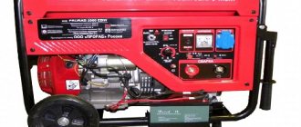
Usually a voltage of 220 volts is used, but the device can also be made for a voltage of 380 volts. Three-phase devices have slightly higher performance.
How to use a homemade device
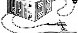
After connecting a homemade device to the circuit, the controller will automatically set a certain current strength. If the wire voltage is less than 100 Volts, this indicates a malfunction of the device. You will have to disassemble the device and recheck the correct assembly again.
Using this type of welding machine, you can solder not only ferrous, but also non-ferrous metals. In order to assemble a welding machine, you will need not only knowledge of the basics of electrical engineering, but also free time to implement the idea.
Inverter welding is an indispensable thing in any owner’s garage, so if you have not yet acquired such a tool, then you can make it yourself.
Power supply assembly
Installation begins with winding the transformer; its function is to provide stable voltage to the parts following it. For its manufacture, ferrite W 7x7 (W 8x8 is possible), on which windings of different numbers of turns are wound: one hundred, fifteen, fifteen and twenty, respectively 0.3; 1; 0.2 and 0.3 millimeters.
To reduce the harmful effects of a possible drop in mains voltage, rings of wire must be placed across the entire width of the coil.
The primary winding must be insulated with fiberglass and a screen made of 0.3 mm wire must be wound. It should cover the entire width of the frame, and the direction of the turns should coincide with the previous winding.
The sequence of work with the remaining windings is the same. The output should be between 20 and 25 volts. It can be adjusted by selecting parts. The sinusoidal current is converted into direct current using diodes connected like an “oblique bridge”, and for cooling it is necessary to select radiators, possibly from an old computer.
One cooler is fixed to the upper parts of the parts and insulated with a mica gasket. The second is to the bottom of the bridge and is attached using thermal paste.
The outputs of the diode bridge are directed to the same place where the contacts of the transistors, which work as converters, will go out. The length of the wires that connect the bridge and transistors is no more than 15 centimeters. The power supply and inverter unit are separated by a metal plate welded to the base.
Manufacturing of transformer and choke
The main task of the transformer is to convert the voltage of high-frequency current with sufficient strength. The cores can be used model Ш20×208, in the amount of two pieces. You can create the gap between the parts yourself using plain paper. The winding is made with your own hands, with a copper strip 40 mm wide, the thickness should be at least 0.2 mm. Thermal insulation is achieved using cash register thermal tape; it demonstrates good wear resistance and strength.
How to make a transformer for an inverter
The use of copper wire when winding the core is unacceptable, because it forces current onto the surface of the device. To remove excess heat, a fan or cooler from the computer power supply, as well as a radiator, are used.
The inverter unit is responsible for the throughput of the electric arc through the use of transistors and chokes.
For a stable welding process, it is recommended to use several transistors in a parallel circuit rather than one more powerful element.
Due to this, the output current is stabilized; during the process of inverter welding with your own hands, the device produces less noise.
Homemade choke
Capacitors connected in series are responsible for several functions:
- Resonant emissions are minimized.
- Ampere losses due to the design features of transistors, which open much faster than they close.
Homemade transformer as the basis for an inverter
Transformers get very hot due to the large volume of passing current. Radiators and fans are used to control the temperature. Each element is mounted on a radiator made of heat-dissipating material; if it is possible to install one powerful cooler, this will reduce assembly time and simplify the design.
Installation of the power unit
This block is a transformer, which reduces U and increases current. To make it you need a pair of cores Ш 20х208. To isolate them from each other, it is fashionable to use paper.
Winding is performed with a strip of copper, the width of which is 40 millimeters and the thickness is 0.25 millimeters. To lay the turns, you can use good quality paper, and the secondary winding is formed by laying a fluoroplastic strip.
There is no need to mount a step-down transformer using a thick wire because the current, having a high frequency, passes along the surface of the conductor and it does not heat up inside.
The heating of the device parts must be reduced by forced cooling. A fan from the computer system unit is suitable for this purpose.
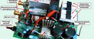
Assembling the inverter unit
To make a welding inverter with your own hands, you need to move on to the next stage - installing the inverter unit. Since this node converts current from direct to alternating, powerful transistors are needed that will open and close, creating a high frequency.
In the instructions for making a simple inverter, you can include a diagram of the inverter unit.
Immersion blender - which company is better to choose for your home? Photo+video reviewsDIY tester: instructions, diagrams and solutions on how to make a simple homemade device. Step-by-step instructions on how to make a tester from a smartphone
DIY voltage regulator: master class on how to make a simple voltage regulation device
It makes sense to mount this unit using several transistors so that the frequency is more stable and the machine hums less when welding.
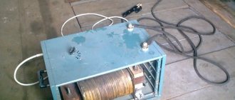
Frame
Step-by-step assembly of an inverter with your own hands involves selecting a reliable housing for such a product. An old computer system unit is quite suitable for this purpose (the older the better, because the metal in it is thicker). You can make a box yourself from sheet metal, and use a half-centimeter or more getinax at the bottom.
Various types of homemade welding inverters have a common feature - this is the control of the operation of the device. A switch, a welding current adjustment knob, wiring contacts, and indicator lamps are installed on the front panel.
Thus, in order to acquire a device that is so necessary for a home workshop, it is not necessary to buy a ready-made inverter. You can study the necessary theory, purchase parts and assemble welding yourself that will work reliably.
Welding current indication
Even if a digital current setting indicator is installed on the inverter, it does not show its real value, but a certain service value, scaled for visual display. The deviation from the actual current value can be up to 10%, which is unacceptable when using special brands of electrodes and working with thin parts. You can get the actual value of the welding current by installing an ammeter.
A digital ammeter of the SM3D type will cost around 1 thousand rubles; it can even be neatly built into the inverter housing. The main problem is that measuring such high currents requires a shunt connection. Its cost is in the range of 500–700 rubles for currents of 200–300 A. Please note that the type of shunt must comply with the recommendations of the ammeter manufacturer; as a rule, these are 75 mV inserts with an intrinsic resistance of about 250 μOhm for a measurement limit of 300 A.
The shunt can be installed either on the positive or negative terminal from inside the housing. Typically, the size of the connecting bus is sufficient to connect an insert about 12–14 cm long. The shunt cannot be bent, so if the length of the connecting bus is not enough, it must be replaced with a copper plate, a pigtail of cleaned single-wire cable, or a piece of welding conductor.
The ammeter is connected with measuring outputs to the opposite terminals of the shunt. Also, for the digital device to operate, it is necessary to supply a supply voltage in the range of 5–20 V. It can be removed from the fan connection wires or found on the board at points with potential for powering control chips. The ammeter's own consumption is negligible.