Design and principle of operation
The functioning of a forging hammer is based on the dynamic impacts of the working body - the rod, connected to the head (the striking part of the machine) and devices that control the force of impact. Other required structural elements are:
- a piston connected to a woman;
- base (fixed on a solid surface);
- bed (guides for moving units are fixed on it);
- drive equipment;
- shield fence (for operator safety);
- electrical equipment;
- compressor cylinder (for pneumatic hammers).
Early machines were either foot or hand driven. A modern forging hammer is equipped with a convenient control system that minimizes the effort of the forge worker.
Rice. 1. Pneumatic hammer device.
(1 - working cylinder, 2 - compressor cylinder, 3 - piston, 4 - crank mechanism, 5 - woman, 6 and 7 - upper and lower strikers, 8 - cushion, 9 - air distribution mechanism, 10 - deformable workpiece)
Briefly, the device works like this:
- the workpiece is placed in the lower part of the hammer (usually the hammer);
- set the device to a certain impact frequency and set it in motion;
- after activating the hammer, the driven upper part hits the workpiece;
- the dynamic effect continues until the workpiece acquires the desired shape.
When a forging hammer operates, the reciprocating movement of the crank mechanism is converted into the same movement of the piston. This allows you to perform many operations on it.
Basic information about hammer design
STUDYING THE DESIGN AND CERTIFICATION OF THE DRIVE
FORGING PNEUMATIC HAMMER
Goal of the work:
studying the design and operation of a driven forging pneumatic hammer, determining its basic passport data, gaining skills in drawing up a passport for a pneumatic hammer.
Basic information about hammer design
Driven pneumatic hammers are designed to perform various forging works carried out by forging: broaching, upsetting, piercing holes (through and blind), cutting, bending, forge welding, etc. On pneumatic hammers, stamping in backing dies is possible. Stamping in closed dies is unacceptable, since the harshness of the blows can lead to breakage of the die.
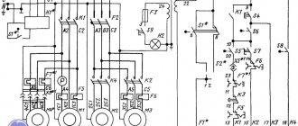
Driven pneumatic hammers (Fig. 1.1) operate using air supplied from the surrounding atmosphere into the compressor cylinder 6 and subjected to compression and discharge during the reciprocating movement of the compressor piston 8. The compressor piston 8 is driven by the drive electric motor 1 through a V-belt drive 2, gearbox 3, crank 4 and connecting rod 5. It should be noted that in the kinematic chain of the electric motor-piston compressor there may not be a gearbox. In this case, the connecting rod 5 is connected to the crank shaft, on which the flywheel is rigidly mounted. The gearbox is necessary to reduce the crank speed.
The following designations are introduced in Fig. 1.1: 1 – drive electric motor; 2 – V-belt drive; 3 – helical gearbox; 4 – crank shaft; 5 – connecting rod; 6 – compressor cylinder; 7 – working cylinder; 8 – compressor piston; 9 – piston of the working cylinder; 10 – air distribution mechanism; 11 – hammer frame; 12 – woman; 13, 14 – upper and lower striker; 15 – shabot; 16 – vibration isolation of the chabot.
According to the principle of operation, pneumatic hammers differ from steam-air hammers, in which the falling parts are accelerated under the action of steam or compressed air entering the working cylinder. For pneumatic hammers, as can be seen from Fig. 1.1, the air provides only a non-rigid connection between the compressor 8 and working 9 pistons, being an elastic cushion that transmits movement from the compressor piston 8 to the working piston 9. The number of hammer blows per minute is equal to the number of revolutions of the crank 4.
a – general view; b – layout diagram of control handles
air distribution mechanism (1-3 – handle positions)
Figure 1.1 – Design of driven pneumatic hammers
The upper movable striker 13 is fixed to the head 12, and the lower fixed striker 14 is attached to the striker 15.
Pneumatic hammers are produced with a mass of falling parts (MPM) of 50...1000 kg and with an impact energy of 0.8...28 kJ. The speed at the moment of impact can be 5...7.5 m/s. The mass multiplicity is 12.
The movement of the compressor piston is a movement with one degree of freedom, determined by the crank angle (Fig. 1.2). The working piston is in the lowest position; in this case, the firing pin is on the forging, and the compressor piston is in the highest position (Fig. 1.2, a
). In this position, the upper and lower cavities of the compressor cylinder are connected to the atmosphere, and the initial pressure in them is set equal to atmospheric pressure. The same pressure is established in the upper and lower cavities of the working cylinder, since these cavities communicate through taps with the corresponding cavities of the compressor cylinder.
a – initial position; b – upward movement of the working piston;
c – downward movement of the working piston
Figure 1.2 – Scheme of movement of the pistons of the working and compressor cylinder
When the piston of the compressor cylinder moves downward from the initial position, the pressure in the lower cavities of both cylinders increases, and in the upper cavities it decreases. When the pressure in the lower cavities increases to a value sufficient to overcome the force of gravity of the moving parts, frictional resistance and air pressure in the piston cavity of the working cylinder, the working piston will begin to move upward. At the crank rotation angle a2 = p, when the compressor piston takes the lower position, the upper cavity of the compressor cylinder is connected to the atmosphere (Fig. 1.2, b
). At this moment, the lower cavity of the compressor cylinder is not connected to the atmosphere.
At a certain angle of rotation of the crank, the upper piston, rising upward, will close the upper channel and disconnect the upper cavities of the cylinders (Fig. 1.2, c
).
As a result, the stroke of the working piston will begin to slow down, and at some point the working piston will stop in its upper position. In this case, the air in the above-piston cavity of the working piston will be compressed. When the working piston is lowered, the pressure in the above-piston cavity will decrease, and at the moment when it becomes equal to the pressure in the upper cavity of the compressor cylinder, both cavities will be connected through a check valve. The angle a4 at which this occurs is called the exit angle of the working piston from the buffer
.
With further rotation of the crank, the compressor piston approaches its uppermost position, and the working piston approaches its lowest position.
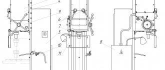
The impact of the striker on the forging usually occurs at a crank angle that is slightly less than 2p. In Fig. Figure 1.3 shows a general view of the studied pneumatic drive hammer model MA4127 with a 50 kg weight capacity.
1 – compressor cylinder; 2 – working cylinder; 3 – handle of the middle tap; 4 – handle of the upper and lower valves; 5 – drive electric motor; 6 – V-belt drive casing; 7 – hammer frame; 8 – crank shaft axis; 9 – working strikers; 10 – control pedal
Figure 1.3 – General view of the studied drive pneumatic hammer
models MA4127 with 50 kg MPC
The structure of the hammer under study is similar to the design shown in Fig. 1.1, with the only difference that in its design there is no gearbox (the connecting rod is driven through a V-belt drive, a flywheel and a crank shaft) and the chabot is installed directly in the frame. The installation of a chabot in the hammer frame is possible due to the smallness of the MF, and, consequently, the impact energy.
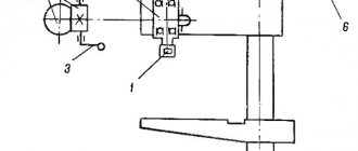
Pneumatic hammers can carry out the following operating modes: idling, holding the hammer in weight, automatic sequential blows and pressing the forging. Some hammer designs have a single strike mode. To implement the above modes on pneumatic hammers, an air distribution mechanism is used, consisting of three horizontal valves (see Fig. 1.1, b
): upper, middle and lower. The upper and lower valves are used to control the operation of the hammer, and the middle one is used to switch the compressor to idle. Between the upper and lower taps in the hammer shell there is a chamber with a check valve.
In Fig. Figure 1.4 shows a detailed diagram of the air distribution mechanism of pneumatic hammers. The upper valve has two sections, and the lower one has three.
Figure 1.4 – Expanded diagram of the air distribution mechanism
pneumatic hammers
Idling
To avoid overheating the compressor during long pauses, it is switched to idle operation. This is done by turning the middle tap to the extreme left position (the tap is open) (see Fig. 1.3, item 3), while the handles of the upper and lower taps are in the middle position (the pedal is also in the middle position).
As a result, the upper cavity of the working cylinder and the upper cavity of the compressor cylinder communicate through the upper valve with the atmosphere through open channel 3 (see Fig. 1.4). The lower cavity of the compressor cylinder also (through the middle valve) communicates with the atmosphere through open channel 4 (at the same time, channels 10 and 11 are also open).
Thus, the compressor works, but the pressure in the cavities of the working and compressor cylinders is equal to atmospheric pressure, and the woman, under her own weight, rests on the lower striker. The hammer is running idle.
STUDYING THE DESIGN AND CERTIFICATION OF THE DRIVE
FORGING PNEUMATIC HAMMER
Goal of the work:
studying the design and operation of a driven forging pneumatic hammer, determining its basic passport data, gaining skills in drawing up a passport for a pneumatic hammer.
Basic information about hammer design
Driven pneumatic hammers are designed to perform various forging works carried out by forging: broaching, upsetting, piercing holes (through and blind), cutting, bending, forge welding, etc. On pneumatic hammers, stamping in backing dies is possible. Stamping in closed dies is unacceptable, since the harshness of the blows can lead to breakage of the die.
Driven pneumatic hammers (Fig. 1.1) operate using air supplied from the surrounding atmosphere into the compressor cylinder 6 and subjected to compression and discharge during the reciprocating movement of the compressor piston 8. The compressor piston 8 is driven by the drive electric motor 1 through a V-belt drive 2, gearbox 3, crank 4 and connecting rod 5. It should be noted that in the kinematic chain of the electric motor-piston compressor there may not be a gearbox. In this case, the connecting rod 5 is connected to the crank shaft, on which the flywheel is rigidly mounted. The gearbox is necessary to reduce the crank speed.
The following designations are introduced in Fig. 1.1: 1 – drive electric motor; 2 – V-belt drive; 3 – helical gearbox; 4 – crank shaft; 5 – connecting rod; 6 – compressor cylinder; 7 – working cylinder; 8 – compressor piston; 9 – piston of the working cylinder; 10 – air distribution mechanism; 11 – hammer frame; 12 – woman; 13, 14 – upper and lower striker; 15 – shabot; 16 – vibration isolation of the chabot.
According to the principle of operation, pneumatic hammers differ from steam-air hammers, in which the falling parts are accelerated under the action of steam or compressed air entering the working cylinder. For pneumatic hammers, as can be seen from Fig. 1.1, the air provides only a non-rigid connection between the compressor 8 and working 9 pistons, being an elastic cushion that transmits movement from the compressor piston 8 to the working piston 9. The number of hammer blows per minute is equal to the number of revolutions of the crank 4.
a – general view; b – layout diagram of control handles
air distribution mechanism (1-3 – handle positions)
Figure 1.1 – Design of driven pneumatic hammers
The upper movable striker 13 is fixed to the head 12, and the lower fixed striker 14 is attached to the striker 15.
Pneumatic hammers are produced with a mass of falling parts (MPM) of 50...1000 kg and with an impact energy of 0.8...28 kJ. The speed at the moment of impact can be 5...7.5 m/s. The mass multiplicity is 12.
The movement of the compressor piston is a movement with one degree of freedom, determined by the crank angle (Fig. 1.2). The working piston is in the lowest position; in this case, the firing pin is on the forging, and the compressor piston is in the highest position (Fig. 1.2, a
). In this position, the upper and lower cavities of the compressor cylinder are connected to the atmosphere, and the initial pressure in them is set equal to atmospheric pressure. The same pressure is established in the upper and lower cavities of the working cylinder, since these cavities communicate through taps with the corresponding cavities of the compressor cylinder.
a – initial position; b – upward movement of the working piston;
c – downward movement of the working piston
Figure 1.2 – Scheme of movement of the pistons of the working and compressor cylinder
When the piston of the compressor cylinder moves downward from the initial position, the pressure in the lower cavities of both cylinders increases, and in the upper cavities it decreases. When the pressure in the lower cavities increases to a value sufficient to overcome the force of gravity of the moving parts, frictional resistance and air pressure in the piston cavity of the working cylinder, the working piston will begin to move upward. At the crank rotation angle a2 = p, when the compressor piston takes the lower position, the upper cavity of the compressor cylinder is connected to the atmosphere (Fig. 1.2, b
). At this moment, the lower cavity of the compressor cylinder is not connected to the atmosphere.
At a certain angle of rotation of the crank, the upper piston, rising upward, will close the upper channel and disconnect the upper cavities of the cylinders (Fig. 1.2, c
).
As a result, the stroke of the working piston will begin to slow down, and at some point the working piston will stop in its upper position. In this case, the air in the above-piston cavity of the working piston will be compressed. When the working piston is lowered, the pressure in the above-piston cavity will decrease, and at the moment when it becomes equal to the pressure in the upper cavity of the compressor cylinder, both cavities will be connected through a check valve. The angle a4 at which this occurs is called the exit angle of the working piston from the buffer
.
With further rotation of the crank, the compressor piston approaches its uppermost position, and the working piston approaches its lowest position.
The impact of the striker on the forging usually occurs at a crank angle that is slightly less than 2p. In Fig. Figure 1.3 shows a general view of the studied pneumatic drive hammer model MA4127 with a 50 kg weight capacity.
1 – compressor cylinder; 2 – working cylinder; 3 – handle of the middle tap; 4 – handle of the upper and lower valves; 5 – drive electric motor; 6 – V-belt drive casing; 7 – hammer frame; 8 – crank shaft axis; 9 – working strikers; 10 – control pedal
Figure 1.3 – General view of the studied drive pneumatic hammer
models MA4127 with 50 kg MPC
The structure of the hammer under study is similar to the design shown in Fig. 1.1, with the only difference that in its design there is no gearbox (the connecting rod is driven through a V-belt drive, a flywheel and a crank shaft) and the chabot is installed directly in the frame. The installation of a chabot in the hammer frame is possible due to the smallness of the MF, and, consequently, the impact energy.
Pneumatic hammers can carry out the following operating modes: idling, holding the hammer in weight, automatic sequential blows and pressing the forging. Some hammer designs have a single strike mode. To implement the above modes on pneumatic hammers, an air distribution mechanism is used, consisting of three horizontal valves (see Fig. 1.1, b
): upper, middle and lower. The upper and lower valves are used to control the operation of the hammer, and the middle one is used to switch the compressor to idle. Between the upper and lower taps in the hammer shell there is a chamber with a check valve.
In Fig. Figure 1.4 shows a detailed diagram of the air distribution mechanism of pneumatic hammers. The upper valve has two sections, and the lower one has three.
Figure 1.4 – Expanded diagram of the air distribution mechanism
pneumatic hammers
Idling
In order not to overheat the compressor during long pauses, it is switched to idle operation. This is done by turning the middle tap to the extreme left position (the tap is open) (see Fig. 1.3, item 3), while the handles of the upper and lower taps are in the middle position (the pedal is also in the middle position).
As a result, the upper cavity of the working cylinder and the upper cavity of the compressor cylinder communicate through the upper valve with the atmosphere through open channel 3 (see Fig. 1.4). The lower cavity of the compressor cylinder also (through the middle valve) communicates with the atmosphere through open channel 4 (at the same time, channels 10 and 11 are also open).
Thus, the compressor works, but the pressure in the cavities of the working and compressor cylinders is equal to atmospheric pressure, and the woman, under her own weight, rests on the lower striker. The hammer is running idle.
Forging machine capabilities
The dimensional hammer is designed to perform the following blacksmith operations:
- bending parts (sometimes the workpiece is preheated);
- drawing (extension of the template by reducing the cross section);
- making holes (a punch/piercing is placed on the rod);
- sediment (reverse action to drawing);
- chopping (using axes).
Some of them are clear.
Rice. 2. Operations performed using a forging hammer.
Most well-known products perform all of the above operations. However, there is an important criterion for their classification.
Hammer assembly and installation
The accuracy of the hammer's operation largely depends on its correct installation (Fig. Installation drawing
). The depth of the foundation depends on the quality of the soil, groundwater level and other local conditions.
Foundation parts are not supplied by the factory.
The lining under the chabot is made from planed beams of dried hardwood (beech, oak). Installation of the chabot on the gasket is carried out according to the level. The deviation from horizontality of the supporting plane of the groove in the cushion should not exceed 0.2 mm over a length of 1000 mm.
After installing the chabot on a layer of beams and aligning the strikers, 2 pieces of beams are laid along the contour of the base of the chabot. from each side. For vibration isolation, inert materials (slag, etc.) are poured between the chabot and the walls of the pit.
The hammer is aligned so that the deviation of the hammer from the vertical position is no more than 2 mm over a length of 1000 mm and the tightness of the contact of the working planes of the strikers in contact does not exceed 0.2 mm per 300 mm of the length and width of the striker.
The chabot must be installed so that the ring mark on the woman is 5-10 mm higher than the lower end of the axle box. After running-in as a result of the settlement of the chabot, the annular mark should coincide with the lower edge of the axlebox, which corresponds to the normal relative position of the chabot and the woman. In the future, you must strictly monitor the correct position of the ring marks.
After filling the wells of the foundation bolts and hardening of the concrete solution, drive counter oak wedges between the frame and the chabot (the slope of the wedges is 2°), you should once again check the installation of the strikers and then finally tighten the nuts of the anchor bolts.
Main details of the foundation (Name/Material, GOST/Quantity):
Beams 130x130x780 Oak (beech), GOST 8486-66. 6 pieces Bars 40x40x740. Oak (beech), GOST 8486-66. 4 pcs Wedges 30x80x280. Oak, GOST 8486-66. 52-62 pcs Pipes d (ø) 125x1300. GOST3262-75. 6 pcs Bolts M30x1380. Steel 35, GOST 1050-74. 6 pcs Bolts M20x450. Steel 35, GOST 1050-74. 4 pcs Nuts M30-6N.56.05. GOST 5927-70. 12 pcs Washers 10x80x100. Steel St.3, GOST 380-71. 6 pcs Washers 90x10. Steel St.3, GOST 380-71. 6 pcs Nuts M20-6N.56.05. GOST 5927-70. 4 pcs Washers 20. GOST 11371-68. 4 things
Installation drawing
Types of devices
This criterion is the type of substance used in the compressor cylinder. Hammers are distinguished:
Rice. 3. Mechanical forging hammer with foot drive.
- steam-air (steam or atmospheric air);
- hydraulic and hydrostatic (fluid under pressure);
- gasoline (work on the principle of internal combustion engines);
- gas (liquefied gas);
- electromagnetic (the energy of electric and magnetic fields is used);
- mechanical (powered by human physical effort);
- spring-spring (the spring accelerates the fall of the piston down);
- pneumatic (gas under pressure).
Among the listed devices, the forging pneumatic hammer stands apart. It has its own pneumatic cylinder, which eliminates the need to use additional energy sources and make the structure heavier. More details about the devices below.
Lubrication
The normal operation of the hammer largely depends on the lubrication of the rubbing parts, which is carried out in accordance with the lubrication scheme. Two lubrication system options are used: multi-outlet lubrication station 22-02 UHL4; electric lubrication station CME.
List of lubrication points (Fig. Lubrication diagram)
1. Compressor cylinder. Lubrication method: from an oil pump.
Frequency: continuous
2. Pump drive lever support. Lubrication method: injection.
Periodic / once a month 3. Pump drive levers. Lubrication method: injection.
Periodic/once a month 4. Lower connecting rod head. Lubrication method: injection.
Periodic / once every two to three months 5. Gearbox. Lubrication method: injection.
Periodic/every three months
| Lubricant | Viscosity at 1000C, cSt | Note |
| Compressor oil K-19 | 17 — 21 | Dropping temperature not lower than 1500C |
| Cylinder oil 24 | 20 — 28 | |
| Konstalin UT-2 |
Instructions for operating the lubrication system Before starting the hammer, you must:
- fill the places indicated in the lubrication diagram with grease;
- fill the oil pump reservoir with compressor oil K-19 or cylinder 24. Fill the oil heated and only through the filter mesh;
- adjust the oil pump so that the oil supply to the compressor cylinder is 0.24 cm³/min. When operating the CME lubrication station, the switching frequency and volume of supplied oil are controlled by a time relay.
During the operation of hammers it is necessary:
- monitor the uninterrupted supply of lubricant, the good condition of the oil pump and the presence of oil in it;
- Clean the oil pump every 1500 hours of hammer operation. To do this, it must be disconnected, removed from its mounting location and washed with gasoline;
- After stopping the hammer for a long time, it is recommended to pour 30-40 g of oil into the compressor and working cylinders.
HAMMER INSTALLATION PROCEDURE
Unpacking and Transport
The hammer and chabot are supplied assembled in wooden boxes or partially packaged. When unpacking, first remove the top panel of the packing box, and then the side panels. Care must be taken not to damage the hammer with the unpacking tool. When unpacking, check the presence and condition of accessories according to the delivery list. The results of the inspection are documented in a preliminary inspection report.
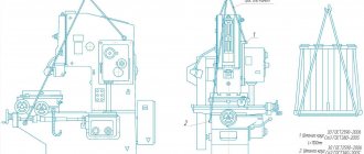
Transportation of the unpacked hammer and chabot is carried out according to Fig. Scheme for transporting a hammer and a chabot using means of appropriate lifting capacity.
Scheme of transportation of hammer and chabot
Procedure for depreservation
Before packaging the hammer, all treated surfaces of the parts are covered with anti-corrosion coatings. After the preservation period has expired, the condition of the parts should be checked and, if necessary, subjected to re-preservation. When reactivating the hammer, a certain sequence of operations is recommended:
- remove the protective paper from the treated surfaces of the hammer;
- Remove the preservation lubricant from the surface of the hammer with a rag.
Metal objects and sandpaper cannot be used for these purposes;
- wipe the external surfaces with clean rags moistened with white spirit. The internal surfaces of the hammer are not subject to re-preservation.
Features of pneumatic hammers
The equipment refers to forging devices that perform all the previously listed operations, as well as twisting, cutting and shaping of workpieces.
They are controlled by hand lever or pedal. Structurally, the forging pneumatic hammer is complemented by an oil pump that lubricates the working cylinders (of which, by the way, there can be two). Conventionally, pneumatic hammers are divided into 2 groups:
- for artistic forging (models with a mass of falling parts up to 75 kg);
- for production (MPF - from 150 to 2000 kg).
The advantages of the equipment are energy intensity, sensitivity of adjustment of operating modes, ease of control, and durability. The disadvantage is the large size and weight, but the need for transportation rarely arises.
How to install hammer MA4132
Preparing for initial launch
The hammer is connected to the electrical network, checking the grounding and compliance of the network voltage with the electrical equipment of the hammer. Before turning on the hammer, be sure to manually turn the crank shaft by the drive pulley to make sure it rotates freely.
After this, you must: a) Check the presence of a ball valve in the buffer device of the working cylinder. The absence of a ball or poor condition of the valve can cause the woman to hit the lid. b) Check the reliability of the wedge fastening of the upper and lower strikers, the fastening of the cushion to the striker, the reliability of the connection of the lower head of the connecting rod with the connecting rod. c) Pour oil into the working and compressor cylinders and into the pump reservoir. If there is no oil in the oil level indicator of the pump reservoir, the hammer cannot operate. d) Follow the instructions from the hammer data sheet, set out in the sections “Electrical equipment” and “Lubrication system” related to start-up. e) Familiarize yourself with the purpose of the control handles according to the air distribution diagram (Fig. Air distribution diagram) and check their operation when the hammer is turned off. f) Run the hammer at idle speed for 15-20 minutes, test all operating modes, check the flow of lubricant into the cylinders. g) Perform test forging of a heated billet with a height of at least 45-55 mm. Start working in the automatic cycle with light, smooth strokes.
Adjustment During operation, it becomes necessary to adjust individual components of the hammer to restore their normal operation. Therefore, it is necessary to carefully monitor the heating temperature of the working and compressor cylinders, which should not exceed 9°C. At least once every six months, it is necessary to check the condition of the piston rings - their joints should not be located opposite the holes in the cylinders.
The tightness of the connecting rod stud nuts on the lower head of the connecting rod should be checked periodically. In addition, it is necessary to ensure that the dimensions of the upper and lower strikers are the same and their edges match.
Considering that air leaks impair the performance of the hammer and reduce the operating coefficient, it is necessary to periodically check the condition of the cylinder covers, the O-rings of the wheel axlebox and the compressor axlebox, as well as the entire air distribution system, promptly eliminating any malfunctions and replacing worn parts with new ones. Systematic adjustment of the tension of the V-belt drive belts is also necessary (especially carefully monitor their tension in the first 48 hours of hammer operation).
The belt tension is controlled by the force Q required to pull the belt branch by a deflection amount equal to 1.55 mm for every 100 mm of the center-to-center distance. For a new belt, Q is 4.6 kg, for a run-in belt - 3.7 kg.
The belt deflection for a certain center-to-center distance should be: L – belt deflection in mm; A – center-to-center distance in mm. Belt tension can also be monitored with a spring dynamometer. If one of the belts fails, the entire set is removed, since it is unacceptable to assemble new belts with used ones.
Instructions for maintenance, operation and repair (instructional and technological map of shift maintenance)
Before starting the shift, conduct an external inspection and check:
- Cleanliness and serviceability of the equipment, absence of foreign objects on moving parts (visually).
- Presence and serviceability of guards on rotating and moving parts (visually).
- Reliability of fastening of components and parts, serviceability of belt drives (visually).
- Availability and serviceability of grounding devices (visually).
Check the presence of lubricant and, where possible, it should be supplied:
- Clean and fill grease fittings contaminated with lubricant, replenish containers and devices with liquid or grease, manually lubricate exposed rubbing surfaces (according to the operating manual and lubrication card).
- Check the oil level in crankcases and containers of centralized lubrication systems (according to the operating manual and lubrication chart).
- Bleed the centralized lubrication systems, check the supply of lubricant to all points accessible for inspection (according to the operating manual and lubrication chart).
Start at idle speed, while checking:
- No extraneous noise (auditory).
- No unacceptable heating at the joints of moving parts (to the touch).
- Operation of the lubrication system (according to the operating manual and lubrication chart)
- No oil leaks (according to the operating manual and lubrication chart).
Make an entry in the operational log indicating the date, position, name and signature. All detected defects must be corrected. At the same time, turn off the power to the hammer.