Lathe 16B20
NovosibirskEkaterinburg Chelyabinsk Surgut Volgograd: +7(8442)78-01-43
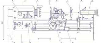
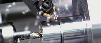
| The 16B20 machine is a universal turning and screw-cutting equipment used for processing the surfaces of workpieces and cutting all main types of threads on them in single-unit and small-scale production. The main advantages of the machine are: • maximum fixation of the tool and ensuring its stability during processing; • rigid bed; • presence of ground and hardened guides; • smooth running of the tailstock; • the presence of blocking and fencing elements to ensure a high level of security; • long service life. Technical characteristics of the lathe 16B20 | |
| The largest diameter of the workpiece being processed, mm: | |
| above the bed | 445 |
| above the caliper | 220 |
| Maximum length of the workpiece being processed, mm: | |
| above the caliper | 750 |
| above the bed recess | 290 |
| above the bed recess when mounted on a faceplate | 240 |
| Maximum turning length, mm | 650 |
| The end of the flanged spindle according to GOST 12593-72 | 6K |
| Center according to GOST 13214-79 | |
| in the spindle | 7032-0043 (M6) |
| in the tailstock quill | 7032-0039 (M5) |
| Diameter of cylindrical hole in spindle, mm, not less | 54 |
| Height of the cutter installed in the tool holder, mm, not less | 25 |
| Number of speeds of direct rotation of the spindle, not less | 24 |
| Number of spindle reverse rotation speeds, not less | 12 |
| Spindle rotation speed, min to -1 degree | 10-1400 |
| Number of longitudinal/transverse feed stages, not less | 50/50 |
| Feed, mm/rev: | |
| longitudinal | 0,018-22,4 |
| transverse | 0,009-11,2 |
| Number of threads to be cut, not less: | |
| metric | 36 |
| modular | 36 |
| inch | 45 |
| pitching | 45 |
| Pitch of cut threads: | |
| metric, mm | 0,5-224 |
| modular, module | 0,5-224 |
| inch, number of threads per inch | 77-0,125 |
| pitch, pitch | 77-0,125 |
| Speed of rapid movement of the caliper, m/min: | |
| longitudinal | 4 |
| transverse | 2 |
| Maximum travel length, mm: | |
| carriages | 650 |
| lower caliper | 280 |
| upper caliper | 130 |
| quills | 150 |
| tailstock (lateral offset) | ±15 |
| Maximum angle of rotation of the upper caliper, degrees | ±90 |
| Price of one division of the movement scale, mm: | |
| carriages | 1 |
| lower caliper | 0,05 |
| upper caliper | 0,05 |
| quills | 5 |
| Price of one division of the upper caliper rotation scale, degrees | 1 |
| Surface roughness of a structural workpiece | |
| steel during finishing turning, mm, no more | Ra 2.0 |
| Machine dimensions, mm | |
| length | 2500 |
| width x height | 1190x1450 |
| Machine weight, kg | 2200 |
www.btsm-stanok.ru
Features of repair of lathe 16b20p
Before repairing a machine, a test run and a comprehensive inspection must be carried out. The decisions made in the end will be the most rational. It is important to pay enough attention to the following machine components:
- The bed is the basis of the machine’s design; the achieved surface roughness of the parts and dimensional accuracy depend on its condition. The presence of significant vibration indicates problems.
- A cutting tool is attached to the support and moves near the part. Like the bed, it experiences significant loads that cause wear.
- The uniform movement of the caliper along and across the axis of rotation of the workpiece is ensured by the apron mechanism, which is carefully inspected.
- Evaluate the operation of feed boxes, speeds, tailstock and electrical equipment.
After identifying defects and shortcomings, they are corrected by replacing a unit, part, unit or repairing them using hand/mechanized tools. The goal of repair operations is to completely restore functionality. For example, if the tailstock malfunctions, its parts are selectively changed. And it’s easier to completely replace electrical equipment.
TIP: Entrust machine repairs to specialists with experience in diagnosing and disassembling such equipment.
Restoration of the lathe bed 16b20p
Most often, guides are repaired on a lathe bed. To restore their flatness, scraping, grinding or longitudinal planing is used. They are hardened with high-frequency currents and the surface is hardened by knurling with a roller. The last two methods increase the resistance of the guides to friction.
The restoration method depends on the hardness of the guide and the percentage of its wear, on the technical capabilities (availability of equipment, machines and tools) of the repair service of the enterprise.
All work begins with installing the frame on a stand or table with level alignment. Scraping is labor-intensive, so it is used for unhardened planes and a relatively small area of defects. The guides are scraped along a straight edge with paint control.
Grinding is more productive than scraping; it is effective in repairing hardened guides and produces a surface with a cleanliness of up to √6. It is made with the end of a cup grinding wheel in two stages:
- Preliminary, the spindle axis is inclined by (1 - 3)o relative to the feed direction of the grinding machine.
- Final, when the axis of rotation of the circle and the plane of the guide are perpendicular.
Heating of the material is not allowed.
The final gouging of the guide is done with a cutter with a wide blade. Class √7 cleanliness is achieved by soaking the metal surface with kerosene. Cutting 0.05 - 0.07 mm of metal should take at least 3 - 4 passes of the cutter.
Screw-cutting lathe 16V20 - 1V62G - Everything for dummies
Details Category: Lathes
Screw-cutting lathes models 1V62G and 16B20 belong to universal technological metal-cutting equipment, used primarily in repair or other metal-working agricultural enterprises. They are used for turning the external and internal surfaces of parts such as bodies of rotation, various axial profiles, as well as for cutting left-hand and right-hand threads ; metric, inch, modular and pitch. The machines are designed for the needs of enterprises of the industrial complex and other sectors of the national economy.
Download documentation
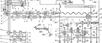
Kinematic diagram
The machine kinematically ensures the receipt of both shaping and installation movements, including the main movement (spindle rotation) and feed movement, as well as auxiliary movements and control movements (for installing and securing the workpiece, approaching and retracting the tool, turning on and off the drives, reversing). Some of these movements, performed manually, are not indicated on the kinematic diagram. The main movement - spindle rotation - is carried out from electric motor 1 through a V-belt drive by pulleys 2 and 3, then through the headstock mechanism (gearbox). The feed movement is carried out from the output shaft XII of the front headstocks through the mechanisms of the gearbox and feedbox, which provide an accurate kinematic connection between the rotation of the spindle and the movements of the tool (cutter) fixed in the tool holder of the support.
bed
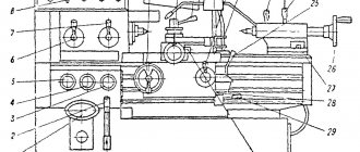
The bed (Fig. 10) is the basic unit of the machine. All other main components of the machine are installed on it. It consists of the actual frame 3, installed on a solid cast base 2, which is also a tray for collecting coolant and chips, motor units: drives of the main movement and rapid movements of the caliper, closed with casings 1 and 14, transmission devices and control handles for the spindle reverse and braking mechanism, as well as lead screw 4, lead shaft 5 with support bracket, electric pump coolant supply unit, centralized lubrication system station and other parts. The motor installation of the main movement drive is located in the niche of the left pedestal of the base, the oil tank and the pump of the centralized lubrication system are also located here. The installation of the drive for rapid movements of the caliper is located on the right end of the frame. The right base cabinet simultaneously serves as a reservoir for the cutting fluid (emulsion). The cooling system pump is also located on it. Frame 3 is cast, cast iron, box-shaped with transverse U-shaped stiffeners. In the upper left part it has horizontal G and vertical B mounting surfaces under the headstock. To the right (in the machine model 1V62G) there is a recess, closed by a removable bridge 22. The presence of the recess allows, with the bridge 22 removed, the processing of workpieces of large diameter. When processing workpieces installed above the recess in the bed, it is allowed to use the movements of the upper support to supply the tool. The upper part of the bridge 22 and the entire upper right part of the frame 3 are two pairs of flat-prismatic guides R and T, which are the base surfaces for installing and moving the carriage with a support (I) and the tailstock (G). The guides are heat-treated (High-frequency hardening 1.5-2.0, 49-53 HRC3) and ground. Under the front guide shelf there is a 25 rail, made up of several parts along the length. With the help of this rack, the longitudinal movement of the carriage during feeds is ensured. At the right end of the frame 3 there is a niche in which the electric motor 15 for driving the fast movements of the caliper is located. Machine mod. 1V62G is supplied with a bridge 22 installed on the frame 3. When processing workpieces with a diameter of more than 445 mm, the bridge 22 is removed. To do this, you need to unscrew the plugs protecting the turnkey recesses in the screws 23 and the threaded hole in the pins 24 and remove the screws 23 and pins 24. In order to protect the bridge removed from the frame from accidental nicks, it must be stored on pads made of soft material, and To protect against corrosion, the treated surfaces should be coated with a thin layer of oil. When assembling (installing) the removed bridge 22, it is necessary to carefully wipe the mating surfaces of the frame and the bridge, remove dirt, as well as random nicks. The fastening screws 23 must be tightened gradually, “by touch,” checking for strict coincidence at the joints of the contours of the guides P under the carriage. IT IS NOT ALLOWED TO PROCESS BLANKETS ABOVE A NOTCH ON A 500 mm DIAMETER PLATE AT SPEEDS EXCEEDING 400 rpm.
When processing unbalanced workpieces, these speeds must be reduced.
Headstock
The headstock (Fig. 11) serves to ensure the transmission of a given rotation speed to the spindle 37, on which devices for securing the workpieces are installed, as well as transmitting movement to the feed chain mechanisms. The headstock includes a manually controlled gearbox and a spindle assembly. It is attached to the frame with five screws M16 and M20 after precise installation “on the line of centers” in the horizontal plane (see instructions in section 18). The headstock mechanisms are driven from the shaft of the electric motor of the main drive 1, rotating at a speed of 1450 rpm, through V-belt transmission 2-3 (see Fig. 9). The drive shaft 79 (Fig. 11) of the headstock has a constant rotation speed. A double-crown gear (z = 47; 52) sits freely on it to transmit forward rotation to the spindle 37, as well as a wheel 99 (z = 47) to transmit reverse rotation. The transmission of rotation from shaft 79 to wheels 3 and 99 is carried out by friction half-clutches, the driving disks of which are seated on the shaft, and the driven disks are on the hubs of the gear wheels. Shaft 77, depending on the position of the moving double block of gears 78-93, receives two direct rotation speeds due to the clutch wheels 4-9 or 5-10 (Fig. 9). Further, due to the clutch of gear pairs 11-25, or 12-24, or 13-23 (Fig. 9), rotation is transmitted to shaft 75 (Fig. 11), and from it - not directly to the spindle 37 through gear pairs 20-27 or 19-28. Spindle 37 (Fig. 11) can also receive rotation through the enumeration mechanism through gear pairs 22-14 or 21-15 and then in pairs 16-17 and 18 -28 (Fig. 9).
By switching wheel blocks 78-93, 90-91-96 105-109 and 10-11 (Fig. 11) using control handles 56 (Fig. 11) and 113 (Fig. 12), you can get twelve options for gear engagement during transmission rotation directly onto spindle 37 and twelve options when transmitting motion through the search.
Tailstock
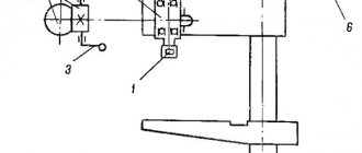
The tailstock (Fig. 14) is used to fix the right end of the workpiece using the center, as well as to secure the cutting tool during axial drilling, countersinking and reaming. The tailstock is located on the machine bed on the right. If necessary, the tailstock can be manually moved along the frame guides and secured in the desired position with handle 10 (by moving it “away from you”). The movement of the quill 1 is carried out by rotating the flywheel 11 by means of a screw pair 4-6, and securing it in the desired position by the handle 50. The release (pushing out) of the center (tool) installed in the conical hole of the quill is carried out by the end of the screw 4. To do this, the quill 1 is moved to the right by the flywheel 11 stop To prevent rotation of the tool, there is a stop 3 in the conical hole of the quill. The transverse displacement of the tailstock (for example, when processing flat cones on a workpiece installed in the centers) is carried out using screws 38 and 43. To protect the rubbing surfaces from contamination, protectors 22, 29, 32 are installed , which should be washed and cleaned monthly. To dismantle the eccentric 19, it is necessary to combine the counterbore G with the screw 30 and, unscrew this screw, release the eccentric 19 from its fixation in the axial direction and remove it from the housing hole.
ATTENTION! It is not recommended to drill in one pass with drills installed in a quill, in steel, holes with a diameter of over 25 mm, in cast iron, over 28 mm. In this case, the quill must be moved manually using the flywheel 11 without the use of additional levers.
Transmission
The gearbox (Fig. 15) is used to transmit rotation from the output shaft of the headstock to the drive shaft of the feed box and regulate its frequency (by rearranging toothed replacement wheels) when setting up the machine for turning and cutting metric, inch modular or pitch threads (see subsection 7.4 .5). It is a guitar of replaceable gears with an intermediate axis of variable position, located between the output shaft of the headstock and the drive shaft of the feed box. Changing the position of the intermediate axis
ATTENTION! When securing the slope and axle 2, it is necessary to ensure optimal clearance in the engagement of the replacement wheels.
Gearbox
The feed box (Fig. 16 and 17) is designed to obtain a number of precise gear ratios of the kinematic feed chain. With the help of the feed box, the relative movements of the cutting tool and the workpiece necessary for efficient and productive work are carried out, ensuring that parts of the desired configuration are obtained with the required accuracy and cleanliness of the machined surface. The feed box is located on the left side of the machine on the front vertical base plane of the frame and is driven from the output headstock shaft through replaceable gears of the gearbox (Fig. 15). The gear mechanisms of the feed box (rns. 16) make up the dial/multiplier. II and dividing group III.
The set group includes gears of the main series 34-46, 50-51, 49-52, 48-53, 47-54 (Fig. 9) and a reversibility link 45-55, 44-56, which has two gear couplings. When the gear couplings are engaged, rotation from shaft XVI is transmitted through gear 34-46, gear coupling, gear 44 and then to shaft XVIII through one of gears 50-51, 49-52, 48-52, 48-63 to 47-54. From this shaft through the second gear coupling of the reversibility link - to shaft XXI and the multiplying group. In this case, the feedbox mechanisms are adjusted to feed during turning or to cut modular and metric threads.
Apron
The apron (Fig. 18, 19 and 20) is designed to convert the rotational movement of the lead screw and the running shaft into the translational movement of the carriage and transmit the rotational movement of the running shaft to the transverse movement screw of the support, as well as for manual control of these movements during operation of the machine (turning on and off working and accelerated movements of the carriage and support, reversal of movements, etc.). The apron is located in front of the machine, under the protruding part of the carriage, to which it is attached with screws. The lead screw and the run shaft, connecting the apron mechanism with the feed box mechanism, are passed through the rear bosses of the apron body through special bushings that provide ease of installation and removal of the lead screw and lead shaft protective shields.
Carriage and support
The carriage and support are the executive body of the machine, designed to carry out precise coordinated mechanical or manual working and auxiliary movements of the cutting tool in the longitudinal and transverse directions relative to the axis of the workpiece (spindle axis) in the same horizontal plane with this axis, as well as for quickly changing the cutting tool and installing it at an angle to the spindle axis when turning cones, carried out manually, by moving the upper slide of the support. The unit has a cross-shaped design, which allows for smooth and precise movements of its moving parts with great rigidity and vibration resistance. The upper part of the caliper with the tool holder can only be moved manually by rotating the handle 47 (Fig. 22). The lower part of the support and the carriage can be moved respectively in the transverse and longitudinal directions, both manually and mechanically. Moreover, their mechanical movement can be operational, i.e. carried out from the feed drive, or fast, carried out from the fast movement drive.
The handle of the cross feed screw 28, 29 is equipped with a special device that turns it off when the mechanical drive of the feed and the high speed of the cross slide of the caliper is turned on. The middle part of the caliper 7, if necessary, can be rotated at an angle of ±90°.
Electrical diagram
Turning on the input switch QF1 (Fig. 32) in the presence of voltage in the network is accompanied by the lighting of the lamp HL2. The electric motor of the main drive Ml is started when the input switch QF1 is turned on by pressing the SB1 button of the push-button station, which closes the coil circuit of the magnetic starter KM1. In this case, the magnetic system of the starter is triggered and closes its normally open main and auxiliary contacts KM 1, i.e. the magnetic starter KM 1 will switch to self-powering, because one of its auxiliary contacts will close the coil power circuit parallel to the SBI button and when the latter is released, the circuit will not break; the electric motor of the main drive M1, powered by the power circuit through the closed main contacts of the KM1 starter, will turn on; the HL1 light will light up, indicating the on state of the electric motor M1, because . the second auxiliary contact KM1 will close its power supply circuit. ATTENTION! Starting is possible only when the contacts of the limit switch SQ2 for blocking the chuck guard are closed in the version of the machine with electrical interlocking. The main drive motor M1 is stopped by pressing the button of the push-button station SB2. In this case, the coil circuit of the magnetic starter KM1 will open, it will be de-energized, all contacts of the starter will open, i.e. the electric motor M1 will turn off and the HL1 light will go out, the self-supply circuit of the magnetic starter will break. The fast motion electric motor M3 is started by pressing the push button built into the apron handle and acting on the limit switch SQ1. The normally open contact of the limit switch, when the button is pressed, closes the power circuit of the electromagnet coil of the starter KM2, which in turn closes the contacts KM2 of the power circuit of the high-speed motor. When the jog button SQ1 is released, the control circuit will open and the starter coil will be de-energized, i.e. the KM2 contacts will open and the M3 electric motor will turn off. Starting and stopping the electric pump M2 is carried out using switch SA1 installed on the front panel of the electrical cabinet (Fig. 8, item 28).
Download documentation
forkettle.ru
Security requirements
The 16V20P machine is certified for compliance with safety requirements. To implement safe operation measures, the manufacturer has provided:
- belt drive guard and replaceable gears, interlocked with the main movement drive control system. When the guard is open, turning on the main movement drive is impossible;
- special locking of the input switch control handle, as a result of which the electrical cabinet door can only be opened when the input switch is turned off;
- chuck guard interlocked with the main movement drive system. When the guard casing is open, it is impossible to turn on the spindle rotation.
There are also other safety measures that guarantee the safety of the operator’s work on the 16V20P machine.
Screw-cutting lathe 16B20
The screw-cutting lathe model 16B20 is designed for performing a variety of turning operations, including cutting metric, modular, inch and pitch threads on workpieces installed in centers or a chuck. Type of climatic modification - UHL4 according to GOST 15150–69. The accuracy class of the machine is N according to GOST 8–82.
All main parts of the machine are made of high quality steel, which ensures their reliable, long-lasting operation.
Heat-treated and ground bed guides, gears and shafts provide long service life and increased machining accuracy.
________________________
Download the passport for the screw-cutting lathe 16B20
Passport
________________________
Technical specifications for the screw-cutting lathe 16B20
| Maximum length of workpiece processed, mm | In the centers Above the guides Above the support | 750 445 220 |
| Spindle | Spindle end according to GOST 12593–93 Spindle hole diameter, mm Center in spindle according to GOST 13214–79 | 6 54 7032–0043 (Morse 6) |
| Drive unit | Number of spindle speeds Speed range, rpm Main motor power, kW | 24 10–1400 7,5 |
| Feeds, mm/rev | Longitudinal feed range Cross feed range | 0,04–24,6 0,02–12,3 |
| Threads | Metric thread pitch, mm Inch thread pitch, nit\1'' Modular thread pitch, module Pitch thread pitch, pitch | 0,5–224 77–0,125 0,5–224 77–0,125 |
| Dimensions, mm | Dimensions for center distances Length Width Height | 750 2550 1190 1450 |
| Machine weight, kg | 1600 |
ostankah.ru
Screw cutting lathe 16B20
Manufacturer: Russia
The 16B20 screw-cutting lathe is designed to perform a variety of turning operations, including cutting metric, modular, inch and pitch threads on workpieces installed in centers or a chuck.
The design and placement category of the machines in terms of operating conditions is UHL4 according to GOST 1515-82E.
The accuracy class of the machines is N according to GOST 8-82E.
The machines use standardized apron units 16B20P.061 and feed boxes 16B20P.070.
Model Value
| Main settings | GOST 440-81 |
| The largest diameter of the workpiece being processed, mm: | |
| 445 |
| 220 |
| Maximum length of the workpiece being processed, mm: | |
| 750 |
| The end of the flanged spindle according to GOST 12593-72 | 6 |
| Center according to GOST 13214-79 | |
| 7032-0054(Meter.80) |
| 7032-0039(M5) |
| Diameter of cylindrical hole in spindle, mm, not less | 70 |
| Height of the cutter installed in the tool holder, mm, not less | 25 |
| Number of speeds of direct rotation of the spindle, not less | 24 |
| Number of spindle reverse rotation speeds, not less | 24 |
| Spindle rotation speed, min to -1 degree | 10-2000 |
| Feed, mm/rev: | |
| 0,032-28 |
| 0,016-14 |
| Limits of parameters of cut threads with one set of replacement wheels, not less than: | |
| 0.5-224 |
| 0.5-224 |
| 77-0.125 |
| 77-0.125 |
| Speed of rapid movement of the caliper, m/min: | |
| 4,0 |
| 2,0 |
| Maximum travel length, mm: | |
| 650 |
| 280 |
| 130 |
| 150 |
| ±15 |
| Maximum angle of rotation of the upper caliper, degrees | ±90 |
| Price of one division of the movement scale, mm: | |
| 0.1 |
| 0,05 |
| 0,05 |
| 5 |
| Price of one division of the upper caliper rotation scale, degrees | 1,00 |
| Drive power, kW: | 6/7,1 |
| Machine dimensions, mm | 2500x1220x1510 |
| Machine weight, kg | 2200 |
| Designation | Name | Col. | Note |
| 16В20 | Complete machine | 1 | |
| 1V62G | Complete machine | 1 | |
| included in the kit and cost of the machine Replacement parts | |||
| Quantity | |||
| 1V62G, 16V20 | |||
| 1V62G.81.72 | Gear | 1* | z=40 |
| 1V62G.81.73 | Gear | 1* | z=64 |
| 1V62G.81.74 | Gear | 1* | z=73 |
| 1V62G.81.75 | Gear | 1* | z=86 |
| 1V62G.81.76 | Gear | 1 | z=36 |
| 1V62G.81.77 | Gear | 1 | z=44 |
| 1V62G.81.82 | Gear | 1 | z=60 |
| Spare parts | |||
| 1V62G.24.299 | Overlay | 1 | |
| Other machine parts dismantled before packaging | |||
| Overlay | 1 | Rubber mat for tailstock | |
| Cartridge 7100-0035 GOST 2675-80 | 1 | 3-jaw self-centering, D=250 mm | |
| Handle 7061 - 0430 A31. 0103.01-89 | 1 | Transverse movement of the caliper | |
| Belt Z (O) - 800 - IV GOST 1284.1-83 | 1 | Oil pump belt | |
| Tool | |||
| 1V62G.83.440 | Key | 1 | To the electrical cabinet, to the gearbox guard. |
| 1V62G.83V.007 | Key | 1 | To lock the input switch |
| 1A62.126 | Key | 1 | To the tool holder |
| Oiler MZhS ShMAI 300593.001TU | 1 | ||
| Documentation | |||
| 16В20.00.000 RE | Manual | 1 |
*Gear wheels are installed on the machine
| Option name | 16V20.1V62G | 1V625M |
| Motorized upper caliper | 180000 | 199000 |
| Mechanic top. caliper part and upgraded apron | 188000 | 221000 |
| Linear Motion Transducer and DRO | No | 243000 |
| Faceplate f 500mm | No | 34000 |
| Longitudinal movement limiter 1-position | 8000 | 8000 |
| Special bracket (Morse taper 5) | 5000 | 5000 |
| Holder for machining large diameters in GAP | 21000 | 21000 |
| Cone ruler | 118000 | 118000 |
| Lock washer with graduated scale | 3000 | 3000 |
| Electromechanical lock on spindle and 3-jaw chuck | 159000 | 159000 |
| Lunette movable | 45000 | 45000 |
| Fixed lunette | 60000 | 60000 |
| Set of devices for installing tools for longitudinal turning of parts over 220 mm | 27000 | 27000 |
www.russtanko.ru
Operating instructions for lathe 16b20p-061
The operating instructions are necessary for lathe workers, specialists in adjustment, maintenance and repair of machine equipment, process engineers developing metal cutting processes, and standard adjusters involved in detailing the operations performed. The instructions should facilitate the correct operation of the machines and help performers master their most effective use. The document contains information about the design of the equipment, its installation, power supply connection and the first commissioning of the machine.