Catalog
Metalworking equipment
- Drilling machines
- Grinding and grinding machines
- Screw-cutting lathes
- Dust collection units
- Band sawing machines for metal
- Cutting machines
- Metal milling machines
- Surface grinding machines
- Metal sharpening machines
- Slotting machines
- Cross planers
- Profile benders
- Sealing machines
Forging and pressing equipment
- Hydraulic presses
- Crank stamping presses
- Combined press scissors
- Pneumatic forging hammers
- Hydraulic guillotine shears
- Mechanical guillotine shears
- Pneumatic guillotine shears
- Plastic injection presses
- Three-roll rollers
- Press brakes
- Sheet bending machines
- Pipe bending machines
- Manual three-roll rollers
- Manual sheet bending machines
- Blacksmith Kits
- Hammers
Equipment for machine tools
- Metal cutting tool
- Spare parts 2S132, 2S135, 2N135, 2L135
- Spare parts for dust collection units
- Spare parts for shear presses
- Spare parts for guillotine shears NG13, NG16
- Spare parts for hammers
- Spare parts for bending machines
- Spare parts for chipping machines
- Spare parts for straightening machines
- Wood cutting tool
- Spare parts for chip ejectors
- Grinding wheels for machine tools
- Machine stands
- Blacksmith pliers
- Oil stations
Metal furniture
- Workbenches
- Elements of workbenches
- Utility cabinets
- Wardrobes
- Cabinet fittings
Machines for working with reinforcement
- Rebar bending machines
- Rebar cutting machines
- Straightening and cutting machines
- Equipment for prestressing reinforcement
- Manual cutting machines
Woodworking equipment
- Wood lathes
- Wood milling machines
- Circular saws
- Wood planing machines
- Band saws for wood
- Grinding machines
- Thicknessing machines for wood
- Combined machines
- Chip suckers
Construction equipment
- Road equipment
- Vibrators for concrete
- Reception and supply of mortar, concrete
- Concrete finishing machines
- Seam cutters
- Troweling (smoothing) machines
- Motor pumps
- Concrete mixers
Lifting equipment
- Telpher, hoist
- Crane support beams
welding equipment
- Butt welding machines
Transformers for heating concrete
Stone cutting equipment
Bending: SGA-1, G-40, G-50, GW40, GW-50 Cutting: SMZh-172, SMZh-322, GQ-40, R-40, R-50 Straightening and cutting: PRA-498, GD- 162, SMZh-357
Drilling machines Quality guarantee Low prices Available 2M112, GS2112, GS2116, 2S125
Home» Forging and pressing equipment» Crank stamping presses
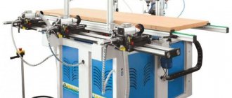
Crank stamping presses are designed for cold stamping operations at various manufacturing and procurement enterprises, auto repair shops, metalworking and turning shops, and even at construction sites.
Such work includes:
- Felling;
- Bending;
- pruning;
- Punching;
- Shallow metal extraction.
The crank press has many advantages, namely: high reliability and productivity compared to hydraulic hammers, which is almost three times higher. During operation, the machines have minimal noise and vibration levels, which allows for high-precision work. Thanks to its multifunctional design, crank equipment can be upgraded with additional accessories, thereby speeding up the work process.
Information about the manufacturer of the single crank press K2019
The K2019 press was produced by the Kursk Forging and Pressing Equipment Plant , founded in 1943.
Currently, the K2019 press is produced by:
- Dolina, PJSC Kuvandyk plant KPO, Kuvandyk, Orenburg region.
- PressMash, LLC Machine Tool Association, Moscow
Machine tools produced by the Kursk Forging and Press Equipment Plant
- K2019
open single-crank press for sheet stamping 80 kN - KD2114
single-crank open press for sheet metal stamping 25 kN - KD2118
single-crank open press for sheet metal stamping 63 kN - KD2318
single-crank open press for sheet metal stamping 63 kN
Varieties
Classification by purpose:
- equipment for the manufacture of parts from sheet raw materials;
- press for long products;
- machines for cutting rods and metal sheets.
Depending on the structural structure, there are two types of presses:
- Simple action. The design of such stamps uses one working part. If necessary, they are equipped with an automatic workpiece feeding system.
- Multiple action. They contain several working parts and additional elements. The entire process is performed in strict sequence established by the manufacturer.
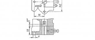
K2019 Dimensions of the crank press die plate
Dimensions of the crank press die plate K2019
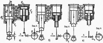
Diagram of permissible forces of a single-crank press by 2019
Ladder logic
As I already said, any circuit on a relay corresponds to a circuit on logical elements. AND, OR, NOT, Delay Line, Trigger (memory cell) - all this is implemented on a relay.
Here is an interesting video that talks about this in detail:
I recommend the site pro-rza.ru for those who work with relay circuits (as well as program algorithms) professionally, and not just based on intuition). You can also find a lot of interesting information on the topic if you enter the query “relay logic circuits” in Yandex.
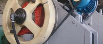
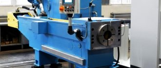
K2019 image of single crank press
Photo of single crank press k2019
Photo of single crank press k2019
Photo of single crank press k2019
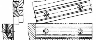
Location of the main components of the K2019 single-crank press
Location of the main components of a single-crank press by 2019
- Bed K2019-11-001
- Drive K2019-21-001
- Eccentric shaft K2019-23-001
- Command apparatus - K2019-24-001
- Installation of clutch-brake K2019-26-001
- Slider K2019-31-001
- Air duct KE2118.01-41-001
- Drive guard K2019-71-001
- Command apparatus fencing - KE2114.01-72-001
- Work area fencing -
- Electrical equipment K2019-91-001
- Push-button control station KE2114.01-92-00
- Flywheel -
- Pneumatic blower
Rotary and roller forging equipment
At large manufacturing enterprises, roller-type conveyor equipment is often used to perform forging operations. The workpieces are processed using the crimping method, which is performed by rotating rollers. Rotary forging machines operate on a similar principle, the processing of parts in which is also carried out during the rotation of the working bodies.
One of the most common actions that are performed with metal is the so-called stamping. In fact, stamping can be called any deformation of the material, which as a result gives the desired shape to the product, or knocks out the necessary relief on it. Stamping can also be considered as stamping a pattern onto a material, making holes in it, either through or not.
All these operations occur solely through the use of equipment such as a stamping press in production. Today there are two main types of stamping: sheet and volumetric methods of deformation of materials. The materials themselves that are subject to this effect are, as a rule, metal, but stamping is also often done on plastic.
Stamping presses can be classified into types. Today there are presses of a mechanical type, these are also called eccentric. Presses can also be crank or hydraulic. The operation of a crank press is, as a rule, needed where cold stamping operations are required. Such work includes punching, cutting, and material drawing, which is shallow.
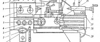
Location of controls for single crank press K2019
Location of controls for single crank press K2019
- Pedal
- Input switch
- Operating mode switch
- Counter
- Light signaling
- Local lighting switch
- Button "Stop continuous strokes"
- "General stop" button
- Button "Start electric motor"
- Buttons "Slider stroke" (Two-handed activation)
Zero protection
I already wrote about zero protection in an article about emergency circuits in industrial equipment. The main idea is that the machine should not start rotating when the power is turned on. You must first return all the mechanisms to their original state, press the ready button, and only then can you start the engines.
For example, this principle is inherent in the zero protection of lathes - when power is applied, the engine cannot be turned on until the gearbox is brought to the neutral position.
I propose a circuit that, when power is applied, checks that the pedal is not pressed, which will be indicated by the switched on relay KA3:
Zero protection circuit
When the SB pedal is briefly pressed, relay KA3 continues to remain on in self-retaining mode, and KA1 becomes self-retaining. The EM is turned on through relay contacts KA1 and KA3. When the sensor is deactivated (end of cycle), both relays are reset. Due to inertia, the sensor becomes active again, and KA3 turns on. The circuit is ready for use again.
This scheme eliminates spontaneous activation of the press in case of problems with the pedal - getting stuck, pressing with an arbitrary object.
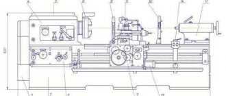
Kinematic diagram of single-crank press K2019
Kinematic diagram of the K2019 single-crank press
List of kinematic diagram elements
- Electric motor
- Drive pulley
- Drive flywheel
- Clutch-brake
- Eccentric shaft
- screw
- Eccentric bushing
- connecting rod
- Adjustment screw
- Crawler
- Ejector stop
- Ejector bar
- Air supply head
- Bearing
- Bearing
- Bearing
Download files
If you want to know how relay circuits are compiled in science, download an interesting book:
• Logical techniques for compiling and analyzing relay-contact and non-contact circuits / Guidelines (manual) for practical classes in the course “Automated control systems” Direction 220300 - Automated technologies and production , pdf, 304.8 kB, downloaded: 965 times./
Splan file, in which I made the diagrams for this article:
• Press CD / Schemes in SPlan format., zip, 16.7 kB, downloaded: 1234 times./
Description of the press K2019
bed
Press bed fig. 10 is cast iron, box-shaped, absorbs all the forces generated during stamping, and is mounted on two posts 8 and 10 using four pins.
In the upper part of the frame 2, in the cups 11 and 12, there are rolling bearings 13, which serve as support for the eccentric shaft.
On top, on the bevel of the frame 2, there is a plate for the sub-motor plate on which the electric motor is installed.
In front, on specially treated areas of the frame, prismatic adjustable guides 17 for the slide are attached.
The guides are adjusted with screws using threaded connections 14, 15 and 16.
The front part of the frame is closed by door 3.
A stamping plate 6 is fixed on the working plane of the table.
For work without failure, holes are provided on the table and plate.
An inclined slide 7 is attached to the lower part of the frame to remove stamped parts or waste.
Drive unit
Drive (see kinematic diagram in Fig. 9).
The slider stroke is adjusted by rotating the eccentric sleeve 2, which is connected to shaft 1 through a gear and is disengaged by rotating the nut 3.
After setting the required stroke value of the slider, the eccentric sleeve is brought into engagement with the eccentric shaft by rotating nut 3, which is locked with screw 6.
The required amount of slider stroke is set on scale 4 using pointer 5.
Installing the clutch-brake (Fig. 12)
The clutch-brake installation consists of a flywheel 1-3 and a clutch-brake 5-14, mounted on the eccentric shaft 4 of the press, an air supply head 15-18, mounted on the clutch-brake and a bracket 21, connected by pins 20 to the clutch-brake and mounted on press bed.
The flywheel 1 is supported by radial ball bearings 2, mounted on a sleeve 3, which in turn is mounted on an eccentric shaft 4.
The rigidly interlocked multi-disc friction clutch-brake with pneumatic activation consists of the following parts:
- driving - driving disks 5 of the clutch with friction linings;
- driven - hub 6 with a fixedly attached piston 7, cylinder 8 moving along the axis, intermediate disks 9, support nuts 10 installed along the threads of hub 6 and piston 7, pressure disk 11 mounted rigidly on cylinder 8;
- brake - brake disc 12 with friction linings.
As friction linings 5 and 12 wear, the gap “a” increases, which causes increased knocking when the clutch is engaged and air consumption increases. To adjust this gap, use split nuts 10, which are secured against unscrewing with nuts 13.
The unified air supply head consists of a housing 15, a fitting 16, rubber seals 17 located between them and radial ball bearings 18.
The clutch brake works as follows:
Compressed air through the air supply head 15-18, piston 7, hub 6 enters the pneumatic chamber “B” and moves the cylinder 8 along the axis of the eccentric shaft towards the clutch, which clamps the drive disks 5 of the clutch, which are constantly connected to the flywheel through fingers 19, ensuring the transmission of torque moment through the hub b onto the eccentric shaft 4.
At the moment of braking of the eccentric shaft 4, compressed air from the pneumatic chamber is released into the atmosphere through the air supply head 15-18, while the cylinder 8, under the influence of the springs 14, returns towards the brake and clamps the brake disc 18, sitting on the fingers 20, fixed in the bracket 21, which is rigidly associated with the bed.
Slider (Fig. 13)
The slider is the working part of the press to which the upper part of the die is attached.
The press slide 13 is box-shaped with prismatic double-sided guides. The slider is attached to the eccentric shaft by means of an adjusting screw 5 and a detachable connecting rod 4 in the housing and cover of which there are bronze sleeve bearings 2 and 3, covering the eccentric sleeve.
The total gap between the guides of the slider and the frame should be in the range of 0.04-0.08 mm. The gap in the ball joint should be no more than 0.015 mm. The gap between the bronze bushings of the connecting rod and the eccentric bushing is no more than 0.1 mm.
The ball head of the adjusting screw 5, the lower support 10 and the floating liner 8 are placed in the slider 12. After adjusting the gap in the ball joint, the nut 8, screwed into the slider 12, is locked with a screw 17.
The ball joint is supported by a shear safety washer 13, designed to withstand destruction when the press is overloaded. When cutting off the safety washer, use screw 17 to unlock nut 18, unscrew it 1.5-2 turns, lift the connecting rod with the adjusting screw, turning the press flywheel in the “Manual crank” mode, replace safety washer 13 by removing the cover on the window in the front of the slider , tighten nut 18 and lock it with screw 17.
The size of the die space is adjusted by rotating the adjusting screw by its hexagon; the set size of the die space is fixed by locking bushings 20, which are tightened by a screw with a lock nut 19.
The lower limit of die space adjustment is limited by clamp 23.
The amount of adjustment is determined by ruler 6.
At the bottom of the slide there is a hole for the shank of the upper die plate.
The shank is fastened with clamp 17 using two studs with nuts. Locking screw 15 serves for additional fixation of the stamp shank, as well as for repelling the clamp when removing the stamp.
In the groove of the slider there is an ejector rocker, spring-loaded with two clamps.
Command apparatus. (Fig. 14)
The command device is designed to switch current in the electrical control circuits of the press and control the operation of the pneumatic blower.
The command device is installed on the left end of the eccentric shaft. Aluminum disks 1, 2, 3 are fixed to the sleeve 4. Contactless switches 8, 9 and 10 type BVK 201-24 are installed on bracket 7, fixed to the frame.
- BVK (SQ1), switched by disk 2, controls the solenoid valve of the U7122A pneumatic distributor;
- BVK (SQ2), switched by disk 1, controls another electromagnetic valve of the dual three-line pneumatic distributor (stopping the TDC slide);
- BVK (SQ3) blocks the downward movement of the slider when turned on two-handed (when the slider does not reach BDC, releasing the two-handed turn-on buttons causes the slider to stop).
Selection principles
When purchasing crank hot stamping presses, consider:
- the maximum force achieved by the working mechanism;
- number of slider movements per minute;
- maximum workpiece dimensions;
- electric motor power;
- dimensions of the machine, which must correspond to the room.
Advantages and disadvantages
Advantages:
- increased accuracy of finished products;
- increase in productivity relative to similar hammers by 35%;
- the use of prefabricated structures as a result of the processing technology;
- high reliability of all components;
- reducing the cost of manufacturing one product.
In addition to its advantages, the press also has disadvantages:
- no redistribution of metal along the axis of the part;
- increase in the number of streams;
- complexity of equipment design;
- parts after processing need additional cleaning from scale;
- high price.
Electrical equipment. General information
Electrical diagram of the single-crank press K2019
The electrical equipment used on the press has the following composition and characteristics:
- main drive electric motor - asynchronous three-phase alternating current with a supply voltage of 380 V;
- electro-pneumatic valves УV1, УV2 in the pneumatic distributor У7122А for 24 V DC;
- control cabinet.
The description of the operation of electrical equipment is indicated in the passport for the control cabinet.
Locks
The electrical circuits of the press and control cabinet provide the following interlocks:
- Zero blocking;
- blocking of pneumatic valves;
- blocking the doors of the frame;
- flywheel guard window blocking;
- air pressure switch;
- two-hand control;
- braking angle;
- control valves.
Supplying voltage to the press circuit does not cause spontaneous switching on of electrical devices. This is achieved by inserting the closing contact of the KM magnetic starter into the circuit of its own coil.
Locking pneumatic valves
When one of the pneumatic valves of the U7122A pneumatic distributor is blocked, the microswitch SQ11 or SQ12 is activated and turns off the electric motor and the press clutch.
Lock screen protector
When operating with a pedal, turning on the press clutch is possible only when the screen is closed (the limit switch is pressed in the “Single stroke” mode).
When working with buttons SB3 and SB4 in the “Continuous strokes” mode, the clutch can only be engaged when the screen is closed (the limit switch is pressed in the “Continuous strokes” mode).
Bed door lock
When the frame door is opened, the limit switch SQ15 is released and the electric motor and press clutch are switched off by the normally open contact.
Flywheel guard window lock
When the flywheel guard window is opened, the limit switch is released and the electric motor and press clutch are switched off using a normally open contact.
Air pressure switch blocking
When the air pressure in the system drops, the SP relay is activated and, with its normally open contact, turns off the drive motor and the press clutch, and the red warning light on the control cabinet lights up
Blocking control channels and command device failure
Each valve of the dual pneumatic distributor is controlled from an independent control element of the command apparatus via an independent circuit. If one of the control channels or command apparatus fails, one of the pneumatic valves of the U7122A pneumatic distributor does not operate. Microswitch SQ11 or SQ12 is activated and turns off the electric motor and the press clutch.
Purpose
Hot stamping press is equipment used for forging. The process results in complex parts with projections and depressions. The equipment can produce:
- rods with flanges;
- retaining rings;
- glasses with a complex profile;
- disembarking pipe ends.
It is used for pressing scrap metal into bags that are convenient for storage and further processing. When packaging scrap, metal with low ductility is used. At large industrial enterprises, stamping presses are used for the production of serial and large-scale products. During processing, the material is heated.
Technical characteristics of the K2019 press
Technical characteristics of the single crank press K2019
Technical characteristics of the single crank press K2019
Types of stamping technological operations and equipment
Stamping as a method of processing metal blanks can be:
- hot;
- cold.
The first implies that the metal is processed in a heated state. The great advantage of hot stamping is that when it is performed, the characteristics of the workpiece being processed are improved (in particular, the metal structure becomes denser and more uniform). Meanwhile, a layer of scale is not created on the surface of metal workpieces processed using technology, while the dimensions of the finished products are more accurate, and their surface is smoother.
Depending on the type of workpiece being stamped, such a technological operation can be sheet or volumetric. Stamping of the first type is used for processing sheet metal blanks; this technology is used to produce:
- dishes;
- jewelry;
- weapon;
- medical equipment and instruments;
- parts of watches, household, climate control and electrical equipment;
- parts for completing automotive equipment;
- parts of machine tools and other engineering products.
Finished metal products obtained using technology do not require further refinement. The formation of their geometric parameters when performing volumetric stamping occurs in special forms in which hot or cold metal is subjected to extrusion.
The press machine is usually used for:
- production of metal blanks by forging;
- pressing and pressing out of shafts, bearings and gears;
- performing sheet and volume stamping.
According to the principle of operation, pressing machines can be of the mechanical or hydraulic type and perform metal processing using static or impact methods.
Mechanical pressing equipment can be designed according to its design:
- eccentric;
- crank.
Crank machines are used for both cold and hot. This stamping equipment is also used to perform such technological operations as drawing, cutting and cutting. The hydraulic press is used for stamping and forging technological operations with bulk metal blanks.
According to their functionality, pressing machines are divided into the following types:
- universal;
- special;
- specialized.
A universal pressing machine has the widest functionality; such equipment can be used to perform almost any forging operation. Specialized dies or presses are used to implement one technological process. Special presses that are used for stamping products of one type have minimal functionality, while their operation is based on one technology.