Drilling machines can be classified as equipment with universal capabilities. At the same time with the ability to drill holes of various diameters, cleanliness and accuracy, with their help it is possible to perform numerous operations in accordance with the technological process of surface treatment. The use of this category of equipment is optimal if the technology provides for the following actions:
- drill, bore holes of various diameters;
- countersink the drilled holes to the appropriate parameters, countersink the necessary recesses to accommodate the protrusions of the fasteners;
- expand the surface of the holes within specified limits;
- roll out holes using ball and roller mandrels to a given level of roughness;
- perform internal thread cutting;
- trim (chase) the ends of parts in order to align them.
There are also other possibilities for using equipment in this category.
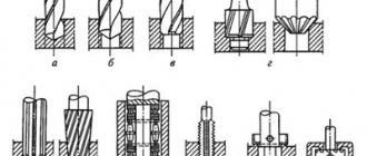
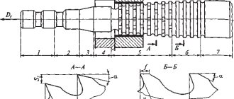
Rice. 1. Work performed on drilling machines
a – drilling; b – drilling; c – countersinking; g – countersinking; d – deployment; e – rolling; g – cutting internal threads; h – cutting (countering) the ends
Metal processing by drilling: basic information
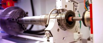
Drilling processing is carried out on special drilling machines, where the workpiece is rigidly fixed, and the cutting tool rotates and at the same time moves translationally along the axis of the hole drilled in the workpiece (this movement is called feed).
There are vertical drilling and radial drilling machines. The former are used for drilling holes in small workpieces, which, during the setting process, are moved along the table so that the axis of the drill and the axis of the future hole coincide. To work with heavy and large workpieces, radial drilling machines are used. On them, the workpiece is immediately rigidly fixed on the table, and the machine spindle is installed in the desired position. Work performed on drilling machines:
- drilling;
- deployment;
- countersinking;
- thread cutting.
Cutting tools used for processing parts on drilling machines:
- drill;
- sweeps;
- countersinks;
- taps (for cutting threads).
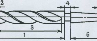
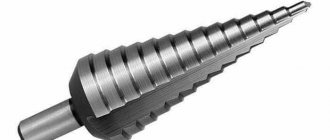
The main cutting tool when drilling parts is a drill. Typically, twist drills are used for this purpose, consisting of a working part, a neck and a shank. The working part, in turn, consists of two parts - cutting and centering. The cutting part has two cutting working edges connected to each other by a bridge. The centering part has a pair of screw strips that act as guides during the process of drilling metal, as well as two spiral grooves through which cutting fluid is supplied and chips are discharged. The shank can have a conical or cylindrical shape. The first option is intended for fastening the drill in the spindle using adapter sleeves, the second option is for fastening it in the chuck. The drill neck carries a masking, where, among other parameters, the diameter of the drill and the material of its cutting edge are indicated.
Drilling methods
Depending on the type of production and the task at hand, metal processing by drilling can be performed in different ways.
Drilling along the jig and along the markings
In small-scale and single-piece production, holes are drilled in parts according to markings. The workpieces arrive to the driller already marked (with the center of the future hole and control circles marked on them). First of all, preliminary drilling is carried out. It is carried out with manual feed, the diameter of the test hole is approximately 0.25D. Next, the spindle with the drill is retracted, the chips are removed and it is checked whether the resulting test circle coincides with the marked control circle. If there is an exact match, metal drilling continues and is completed. If there is a deviation, an adjustment is necessary: in the direction where it is necessary to move the drill, a narrow chisel is used to cut grooves along which it should go to the desired point. After this, drilling continues until the desired result is achieved.
In conditions of mass production, in order to reduce the time for setting up the machine and make the processing of parts on drilling machines more accurate, jigs are used. They are designed to fix the workpiece in the desired position and precisely guide the cutting tool in accordance with the requirements of the technological process. The workpiece is placed in the mounting base, and the direction of the drill is provided by jig bushings. The worker is not involved in setting up the machine and/or checking the accuracy of the settings, but only installs the workpiece, turns the machine on and off, after which he removes the processed workpiece and installs the next one. This reduces the time spent on drilling holes in parts and increases processing accuracy. Conductors are not used in individual production due to the fact that it is unprofitable to make a special device for drilling holes in several parts.
Through and blind holes
Holes that pass through the entire part are called through, and those drilled to a certain depth are called blind. Their drilling processes have significant differences. So, for example, at the moment the drill leaves the workpiece from the opposite side, the drill may jam, or it may break due to a sharp decrease in the resistance of the workpiece material. Considering that operations on a drilling machine are usually performed with mechanical feed, it is necessary to switch to manual feed and reduce the feed speed to the lowest possible.
There are three ways to drill blind holes:
- On machines with a device for automatically turning off the spindle feed, when setting up for the manufacture of a part, the required drilling depth is set.
- On machines without an automatic feed shut-off device, a special chuck with an adjustable stop is used, installing the stop sleeve relative to the body at the required drilling depth (accuracy up to 0.5 mm).
- If greater accuracy in depth is not needed, it is marked with chalk directly on the drill.
Hello student
The production of products of a high class of accuracy and great reliability is based primarily on high precision when machining holes in base and body parts. The overwhelming number of these holes must be processed according to the second accuracy class. In modern designs of machines and machine tools, the number of holes with tolerances of the first accuracy class is growing, while the number of holes of the third and coarser accuracy classes is decreasing. It is also necessary to take into account that in order to long-term preserve the precision parameters of the machine, the technological process must ensure the production of holes using no more than 60-70% of the tolerance field of the corresponding accuracy class, and for the accuracy of geometric shapes - half the tolerance. For example, the ovality and taper of the main holes for the spindle of jig boring machines should not exceed 0.003 mm, and the misalignment of the holes for the spindle bearings should not exceed 0.007-0.01 mm.
Methods for processing holes in body and base parts are varied. They depend on the serial number, dimensional and geometric accuracy of the holes, and the design features of the parts. When choosing a method for processing precision holes, it is necessary to ensure: a) dimensional and geometric parameters of the holes; b) straightness of the geometric axis of the holes; c) the necessary relationship between the geometric axis of the holes and other axes and surfaces of the part.
For hole machining, it is necessary to make the optimal decision on the choice of single-edge and multi-edge tools, each of which has its own pros and cons and its most rational areas of application. It is known that the straightness of the hole axis is better achieved when working with a single-edge tool, and the hole size is better achieved when working with a precision multi-edge tool. However, these general conditions have been seriously revised in recent years in connection with the solution to the problem of tool setting outside the machine and the creation of micro-boring tools. Significant changes in hole processing technology arise when deciding whether to base a boring tool in two supports or use a cantilever tool, including processing holes located on the same axis with a part rotated 180°.
Below we discuss the technological features of the most common methods of processing holes: processing in devices with guide bushings for boring bars, processing holes with a console tool, finishing holes using fine boring methods.
With significant diversity in methods, equipment and tools for machining holes, most factories use approximately the same number of transitions to machine a hole of a certain diameter and accuracy class. So, for example, usually to process a hole Ø 80-120 mm in the second class of accuracy, four technological transitions are required, and in the first class - five. Using “trepanning” a hole in solid metal instead of boring a cast hole can reduce the number of transitions required.
Boring of holes using devices with tool guides is widespread in serial and large-scale production. In this case, both universal horizontal and vertical boring machines and aggregate multi-spindle and multi-position machines are used. In small-scale production, it is advisable to use boring devices for repeating production or in cases where it is possible to process a group of structurally similar parts in one device. The advantage of boring devices is that they can be successfully used on old equipment that has lost its accuracy. Under these conditions, accuracy is achieved due to the double direction of the boring bar in the fixture, and the coordinates of the holes are determined by the placement of the bushings in the fixture; The spindle of the machine performs only the role of a drive or, as it is called, a “carriage”.
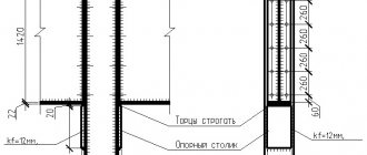
In Fig. Figure 19 shows the design of a device for installing and securing the bracket when boring holes and machining ends on a horizontal boring machine. The device uses the method of basing the part on a supporting surface and two technological holes made according to the second class of accuracy.
The workpiece is installed on the reference plane 1 and two pins - cylindrical 2 and rhombic 3, which fit into the technological holes on the reference plane of the part. The part is secured by two clamps 4, interlocked through the rocker arm and driven by a nut 5. The racks of the device, which house the quick-change rotating bushings 6, are spaced apart for free access and processing of the two ends of the part.
In Fig. Figure 20 shows a general view of a group device for boring holes in two different parts. The device has two pairs of guide bushings located at an angle of 90°, each of which is used to process a specific part. The part in this device is also based on two technological holes on its supporting surface, and clamping is carried out using folding clamps.
When using boring devices with guide bushings in factories, the problem arises of consistently producing holes in the second accuracy class. Boring devices make it possible to obtain holes of such precision only when using bushings rotating on rollers (needles), boring bars with tight tolerances and dimensional adjustment of the cutting tool outside the machine. Violation of these conditions leads to the fact that the hole sizes “fall out” of the tolerance range and factories are forced to introduce a calibration operation for holes of the second class, performed outside the machine. Holes of the first accuracy class in devices with guide bushings cannot be consistently obtained, and for them a finishing operation of fine (“diamond”) boring is introduced.
When using boring fixtures to machine body and base parts with holes on multiple axes, it is difficult to place guide bushings for closely spaced axes. Here it is not always possible to use bushings on rollers (needles) and you have to switch to sliding bushings, which reduces the accuracy of alignment of the boring bars. The main disadvantage of large boring devices designed for machining closely spaced holes is their complexity, high cost and inability to use when making design changes to workpieces.
Rice. 19. Device for boring holes and processing the ends of the bracket:
1 - support plates; 2 and 3 — locating pins; 4 - clamps; 5 — clamp nut; 6 - quick-change rotating bushings
Rice. 20. Group boring device for sequential processing of two parts:
1 - support plates; 2 and 3 — locating pins; 4 — folding clamp; 5 - clamping handle
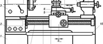
Rice. 21. Device for processing holes in the tailstock housing of a screw-cutting lathe:
1 - guide prism; 2 - support plate; 3 - lever at
grip
for pressing against the stop (pin - 4);
5 — hinged hinge bolt of the clamp with nut 6; 7 — folding clamp; 8 — device body. The necessary change in the coordinates of the bored holes cannot be performed in a device with guide bushings. For all these reasons, the use of boring devices in industry is noticeably declining. They justify themselves mainly with stable production, without design changes.
In some cases, it is advisable to transfer boring operations when processing body parts from boring machines with devices with two tool guides (front and rear) to radial drilling machines. This reduces auxiliary time and overall time spent on operations. In this case, the device is installed on a rotary stand with a horizontal axis of rotation, which makes it possible to process holes from several sides in one installation.
The device shown in Fig. 21, is intended for processing holes in the tailstock housing of a screw-cutting lathe on three sides. The workpiece is based on the prism 1 and the support bar 2, is pressed by the lever device 3 to the pin 4, and then, using hinge bolts 5 and nuts 6, is secured with folding bars 7. The device, mounted in the housing 8, is installed on a dividing stand with a diameter of 500 mm with a horizontal axis rotation and allows you to process the main hole for the quill, holes in the supporting plane, the ends of the bosses and other holes.
Research work aimed at improving the accuracy of machining holes in boring devices has acquired great practical importance. Such work includes research conducted by the Krasnodar Polytechnic Institute together with the Orgstankinprom Institute. The research was based on a statistical method, including the collection and analysis of materials on boring devices used by machine-tool factories and on the achieved processing accuracy. As a result, recommendations were developed for the design of boring fixtures and their elements.
The design features of boring fixtures and their elements, as well as the technical conditions for the manufacture and assembly of fixtures, are determined by the required accuracy of center-to-center distances, alignment of holes, parallelism and perpendicularity of the axes of the holes of the parts processed in them.
Boring fixtures with a solid cast body, in which the racks for the conductor bushings are cast integrally with the fixture body, are recommended for machining body parts with one or more parallel axes. The high rigidity of the body and the ability to process mounting surfaces with alignment from the axis of the guide bushings make it possible to obtain stable, high-precision results in the device: parallelism of the axes to the base surface of 0.005-0.01 mm and class 2 hole accuracy.
For a significant number of parallel and perpendicular axes (parts such as gearbox housings or gearboxes), it is recommended to use box-type boring devices. Such devices are technologically advanced in manufacturing and assembly, have high rigidity, and allow processing of body parts with hole accuracy of the 2nd class with coaxiality and parallelism of the hole axes up to 0.01 mm.
The design of boring devices with attached (screwed-in) stands is recommended for machining parts such as brackets with two or more perpendicular axes, with hole accuracy of class 2 and non-perpendicularity of the axes up to 0.01 mm.
The main assembly of boring devices—the guide bushing (for boring bars) is made in the form of a sliding bushing from steels ШХ15, У10А, 20Х, having a hardness of the guide surfaces of HRC 56–62; bimetallic sliding bushing with surfacing of the inner surface with sormite; a bushing rotating on needle bearings with a single-row or double-row arrangement of needles.
Sliding guide bushings for boring bars, when manufactured to tight tolerances, make it possible to ensure a minimum diametrical gap between them, which creates conditions for high precision machining. The main disadvantage of sliding bushings is the danger of “seizing,” i.e., welding of the bushing to the boring bar, which can occur due to insufficient lubrication and unacceptable heating of the boring bar and bushing. Bimetallic bushings (Fig. 22, a), deposited along the hole with sormite, when mated with a boring bar, also deposited with sormite, have a lower coefficient of friction than bushings and boring rods working steel on steel (Table 4).
Bushings on needle bearings can be used with a single-row arrangement of needles - for rigid boring bars, with the ratio of the distance between the supports to the diameter of the boring bar not exceeding 10, or with a double-row arrangement of needles for non-rigid boring bars, when the ratio of the distance between the supports to the diameter exceeds 10.
In Fig. 22, b shows the design of quick-change rotating bushings with a single-row arrangement of needles. The bushing consists of a body 1, which remains stationary in operation, a set of needle rollers 2, a rotating part 3, seals 4 and 5, balls 6 that absorb axial forces, a ring 7 and a liner 8 that compensates for the gap remaining when the needles are set. In table Figure 4 shows the dimensions of five standard sizes of bushings with holes of 32, 40, 50, 65 and 80 mm.
When manufacturing quick-change rotating bushings, the difference in diameters in a set of needle rollers should be no more than 0.002 mm, and the runout of the hole in the rotating part of the bushing after assembly should be no more than 0.005 mm. Bushings rotating with a double-row arrangement of needles (Fig. 22, c) are similar in design and operating principle to bushings with a single arrangement of needle rollers. The main design differences: increased bushing length, assembled bushing body (9 and 10) and two rows of needle rollers 11 and 12, separated by ring 13.
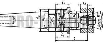
For boring holes with the help of devices, two-support boring bars are usually used in various designs and with different methods of securing the tool in the boring bar. For example, for finishing machining of holes, two types of boring bars can be used: reamer boring bars (rigid reamer, made integral with the body of the boring bar) (Fig. 23, a) and boring bars with mounted floating reamers (Fig. 23, b).
Under similar processing conditions and equal manufacturing accuracy, boring bar reamer devices provide higher stability and accuracy in alignment and relative position of the axes. These boring bars correct the position of the axes.
Boring bars with floating reamers are recommended for use when finishing holes. They do not correct the position of the axes, but provide high accuracy in the size and shape of the hole.
Rice. 22. Bushings—guides for boring devices, rotating, quick-change:
a - bimetallic; b - with a single-row arrangement of needles; c - with a double-row arrangement of needles; 1 — bushing body; 2 - needle rollers; 3 - rotating bushing; 4 and 5 — seals; 6 - balls; 7 - ring; 8—liner; 9— bushing body; 10 — screw ring; 11 and 12 — needle rollers; 13 - intermediate ring; 14 - rotating bushing; 15 and 16 - seals; 17 — balls; 18 - screws
Rice. 23. Boring bar - a reamer with rigid fastening of knives (a) and a boring bar made of 40X steel with attached floating reamers (b)
The designs of boring bars can be such that they work in compression or tension. For finishing 4, especially when the ratio of the distance between the supports to the diameter of the boring bar is over 10, it is recommended that the boring bars work in tension. This reduces the deformation of the boring bar from axial forces and its own mass, which has a significant impact on the deflection of the boring bar, and, consequently, on the processing accuracy.
When processing parts in boring fixtures, the boring bar is connected to the spindle using a conventional bayonet chuck, which allows a certain displacement (mismatch) of the boring bar axis relative to the spindle axis. Research conducted by the Krasnodar Polytechnic Institute revealed the influence of this displacement on the change in the runout value of the working journals of the boring bar. When manufacturing bushings and boring bars with A1/D1 fit, a mismatch of the spindle and boring bar axes of up to 1 mm does not lead to a noticeable change in the runout of the journals under the tool.
When manufacturing bushings and boring bars with rougher fits and increasing the gaps between them to approximately 0.03 mm, a displacement of the boring bar axis by 0.3 mm causes an increase in the runout of the journals under the tool.
When processing parts in boring fixtures, the correct choice of the sequence of technological transitions, the design of the boring tool and the placement of guide bushings in the fixture, interoperational allowances and accepted cutting modes are of great importance. All this is predetermined by the boring scheme, in which the final positions of the tool and the workpiece are drawn on a scale in the order of the technological sequence of transitions. In this case, interoperational dimensions are determined, as well as the dimensions of the tool and guide bushings.
As an example, below we consider the schemes for boring two axes of holes in the bed of a 6R81G horizontal milling machine.
In Fig. 24 and in table. Figure 5 shows a diagram for processing holes 0 32A and 0 28A, located in two walls of the milling machine bed.
The first sketch of the boring pattern (a) shows the location of the holes to be machined and the placement of the tool guides. Considering that the distance between the holes Ø 32A and Ø 28A mm is 326 mm, i.e. the ratio L/D > 10, between them the device is provided with a guide sleeve with a hole Ø 29A mm for the tool. The front wall of the device has two bushings: with holes 40 and Ø 30 mm. The design of the bushings in the diagram is shown conditionally (rotating bushings can be used). The design of the workpiece necessitates the use of a special tool for all transitions.
Rice. 24. Scheme for processing holes 0 32A and 0 28A mm in the bed of a 6R81G milling machine in a fixture on a horizontal boring machine
In the first transition (b), a Ø 32 mm hole in the front wall is drilled to Ø 30 mm. The tool operates in two guide bushings. To perform the second transition (c) - drilling a Ø 26 mm hole in the second wall - a special boring bar and a shortened drill Ø 26 mm were used. The tool also works in two guide bushings: Ø 40 and 29 mm. The third and fourth transitions (d and e) are performed simultaneously for holes Ø 77 32A and 28A. The tool is special boring bars with countersinks Ø 31.75 and 21.75 mm for the third transition (d) and with reamers 0 32A and 28A for final machining of holes (e). In both cases, the tool is supported in two guide bushes (Ø 40 and 29 mm).
In Fig. 25 and in table. Figure 6 shows a diagram of boring holes in the spindle (main) axis of the bed of a horizontal milling machine. The holes are located in three walls, and two holes must be made according to the first accuracy class, one of them is stepped. The operation also provides for counterboring of grooves in the front and rear walls of the frame. The processing of all holes of the main axis is divided into 15 technological transitions (not counting transitions performed in parallel). Roughing and semi-finishing of holes is carried out without changing the boring bar; only the cutting tool is replaced. Rough
Rice. 25. Scheme of boring holes in the main axis of the bed of a 6R81G milling machine in a fixture on a horizontal boring machine in 15 transitions
passes are made with double-sided boring plates, semi-finishing passes with single-sided adjustable plates.
In the first transition, simultaneous rough boring is performed in two walls up to Ø 153 and 118 mm; in the second transition, semi-finish boring of these holes is performed up to Ø 154.8 and 119.8 mm. This is followed by counterbore of the Ø 220 mm recess and boring of the chamfers (3rd-6th transitions), after which the hole 0125 mm is bored with a double-sided plate (7th transition).
In the eighth and ninth transitions, a hole Ø 140П1 mm is bored first to Ø 138, and then 139.8 mm (for reaming). The next three transitions (10, 11 and 12th) include counterbore of a Ø 190 mm undercut and boring of two chamfers.
Reaming of three class holes is carried out separately: Ø 155+0.04 mm with a floating plate, and Ø 120P1 and Ø 140P1 - with mounted multi-blade reamers.
Citing this boring scheme as an example, it is necessary to note the difficulty of consistently producing holes of the first class (120P1 and 140P2) in boring devices. These dimensions can be consistently obtained by fine (diamond) boring. Both shown in Fig. 24 and 25 examples of boring schemes are more typical for mass production conditions with an annual output of 4000-5000 products, since they involve the use of a special boring device and a large number of special cutting and auxiliary tools.
It should be noted that in the conditions of small-scale, and even more so individual, production, boring holes in devices with guide bushings is increasingly giving way to processing with a cantilever tool, without jig bushings. Cantilever boring of precision holes is not a new process. All jig boring machines are built on the use of this method, where the size of the hole is determined by setting the cutter in a precision chuck, and the coordinates of the holes are determined by the machine’s reading devices. Jig boring machines fully retain their importance for tooling and stamping production, and in some cases, when the configuration and location of the part allow this, they are effectively used as production machines for small-scale production.
Along with jig boring machines of traditional designs (with a vertical spindle axis), precision horizontal boring machines with a precise rotary table are increasingly used. Boring of holes on machines of this type is performed with a cantilever tool, which has a rigid structure and, therefore, the ability to increase cutting conditions. A precise rotary table allows machining of coaxial holes located at a large distance from both sides. The machines ensure the accuracy of the location of holes in given coordinates within the range of 0.005-0.001 mm. Boring of holes on machines of this type is usually done with a tool adjusted to the size outside the machine. In this case, it is possible to quickly change boring bars (the machines have a mechanized clamping and release of boring bars) or install cutting inserts configured outside the machine into the boring bar.
The method of processing holes with a console tool is applicable on machines with numerical control and multi-operational machines. Automation of the technological process of processing body parts (on machines with numerical control) requires the sequential commissioning of a large number of different cutting tools, configured outside the machine to a certain size. In this case, automatic commissioning of the tool should be carried out in the shortest possible time, not exceeding 3-5 s for each tool. At the same time, increasing the accuracy of rotation of indexing tables eliminated the need to process holes located on the same axis with an elongated two-support tool. All this predetermined the predominant use of console tools for machining holes on numerically controlled machines. The transition to cantilever hole processing is only part of those new technological solutions that were caused by the use of computer numerical control (CNC) machines. Without considering in this chapter the issues of reducing production preparation time and increasing the flexibility of technological processes achieved with the introduction of CNC machines, we will touch upon the issues of concentrating operations on CNC machines.
The development of numerical control systems not only made it possible to automate the processing cycle on machines of traditional designs, but also caused the emergence of fundamentally new layouts of machine tools with the concentration of the same or different operations on each of them.
Literature used: “Integrated mechanization and automation in machine shops” authors: Zhdanovich V.F., Gai L.B..
Download abstract: You do not have access to download files from our server. HOW TO DOWNLOAD HERE
Archive password: privetstudent.com