Control panel interface
The cutting parameters are controlled using a control panel located on the console, as well as handwheels designed to manually change the location of the slider and vertical support.
The remote control contains (in order from bottom to top and from left to right):
- Signal lamp indicating the presence/absence of lubricant in the mechanical chain of the main drive drive; machine general stop button; switch for moving the faceplate in the “Push” mode; switch for forward and reverse rotation of the faceplate.
- Main drive start button; main drive stop button; button to start moving the faceplate; button to stop the movement of the faceplate.
- Toggle switch for switching lighting lamps; speed switch; step cutting speed switch (additional symbols are marked on the corresponding nameplates).
- Toggle switch for turning on/off the right caliper brake; switch for moving the caliper in operating and adjustment modes.
- Switches for the direction of feeds and movements of the right caliper.
- Light indicator that the right caliper is ready for operation.
- Switches for the direction of feeds and movements of the left caliper.
- Indicators for the operation of the lighting lamps and the readiness of the left caliper for operation.
- Left caliper speed switch.
- General switch for lighting lamps.
On the left side surface of the remote control there are buttons that control the movement of the crossbar of the machine. An indicator indicator of the current load on the drive is installed directly above the console housing.
The remote control is rotated to the position desired by the operator using two handles fixed in the housing.
Manual for electrical equipment of the machine 1525. Rotary lathe.
This operating manual “ Vertical turning machine 1525. Electrical equipment manual ” contains information necessary for the operating personnel of this machine. This manual is an electronic version in PDF format of the original paper version.
CONTENTS
General information
- Brief characteristics of electrical equipment
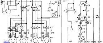
- Electrical circuit diagram of the power supply
- Initial launch
Description of electrical equipment operation
- Electrical circuit diagram for controlling the main drive and cross member
- Electrical circuit diagram of the faceplate control
- Electrical circuit diagram for caliper control
- Control panel wiring diagram
- Control Pendant Wiring Diagram
- Crossbar electrical connection diagram
- Machine electrical connection diagram
- Electrical equipment layout
- Machine lighting
- Electrical equipment protection
Instructions for installation and commissioning of electrical equipment
- Installation
- Setup
- Possible malfunctions and methods for eliminating them
List of electrical equipment
- Certificate of acceptance of electrical equipment
download the manual for electrical equipment of the 1525 rotary lathe in good quality from the link below.
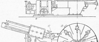
Detailed description of the case
The components of the 1525 rotary lathe include:
- Racks.
- Table with four-jaw clamping device.
- A faceplate with radially arranged T-shaped slots.
- Protective cover.
- Mechanisms that control the movement of moving parts, which use standard electromagnetic couplings.
- Gearbox.
- Gearbox.
- A movable crossbar with a mechanism for its movement.
- Left and right calipers.
- Manual caliper control mechanism.
- Lubrication system.
- Electrical control cabinet.
Unification of the design and attachment points of some components facilitates the installation and dismantling operations necessary during repair work. The maximum cutting force per slide cannot be higher than 15 kN.
Machine 1525. Rotary lathe. Specifications
The technical characteristics of the 1525 machine are the main indicator of the suitability of the machine for performing certain jobs on the machine. For rotary lathes, the main characteristics are:
- largest diameter D of the workpiece (part) being processed
- maximum height H of the workpiece (part) being processed
- Faceplate revolutions per minute n
- Machine accuracy class
Below is a table with the technical characteristics of the vertical lathe 1525. More detailed technical characteristics of the machine can be found in the passport of the machine 1525
| Quantities | ||
| Maximum workpiece diameter | mm | 2500 |
| Maximum workpiece height | mm | 1600 |
| The largest mass of the processed workpiece | kg | 16000 |
| Faceplate diameter | mm | 2250 |
| Faceplate rotation speed range | rpm | 1,6…80 |
| Working feed range | mm/rev | 0.04…16 |
| Main drive motor power | kW | 45 |
| Dimensions (LxBxH) | mm | 5070x6340x5100 |
| Machine weight | kg | 35500 |
Attention! The technical specifications given in the above table are for reference only. Machines produced by different manufacturers and in different years may have characteristics that differ from those given in the table.
Specifications
Kinematic diagram
Workspace dimensions
Connections and seats
Advantages and disadvantages
The 1525 vertical turning lathe is characterized by a number of design solutions that were advanced for its time:
- The main gearbox is equipped with mechanical shifting, including the use of worm gearboxes;
- The tool installation and fastening system is equipped with a pressure indicator, which allows you to promptly eliminate minor current faults;
- The operation of the crossbar fixation mechanism is monitored by sensors and controlled from a remote control panel;
- Provision is made for adjusting the tension of the V-belt drive belts that transmit torque from the electric motor;
- If there are unacceptable clearances in the bearings or lack of lubrication in the rubbing elements, the machine will automatically stop;
- A fuse is used to block the action of the feed mechanism.
At the same time, the design of the 1525 vertical turning lathe excludes its modernization in the direction of introducing an electro-hydraulic monitoring and control system, which would increase the durability of moving parts, reduce the noise level during operation, and contribute to increased cross-bar clamping accuracy.
Machine passport 1525. Rotary lathe.
This operating manual “ Machine Passport 1525 ” contains information necessary both for the maintenance personnel of this machine and for the employee directly involved in working on this machine. This manual is an electronic version in PDF format of the original paper version. This documentation contains the Passport and Manual (instructions) for the operation of the 1525 rotary lathe.
CONTENT
TECHNICAL DESCRIPTION
- Purpose and scope
- Machine composition
- Design and operation of the machine and its components
- Lubrication system
USER MANUAL
- Safety instructions
- Installation procedure
- Setup, adjustment and operating modes
- Regulation
- Features of disassembly and assembly during repairs. Machine repair.
PASSPORT
- General information
- Basic technical data and characteristics
- Repair information
- Information about changes to the machine
- Delivery set
- Certificate of acceptance
- Certificate of conservation
download the passport of the rotary lathe 1525 in good quality from the link below.
Areas of application
The 1525 two-column vertical turning lathe is used for machining workpieces made of ferrous or non-ferrous metals and alloys. The 1525 vertical turning lathe is suitable for use in repair shops and bases.
On the 1525 vertical turning lathe, it is possible to machine large and heavy workpieces of complex configuration, which are distinguished by large radial and relatively small axial dimensions.
Typical operations:
- Face and radial milling of products such as disks, wheels and bushings having surfaces such as bodies of rotation.
- Grinding of dimensional parts.
- Getting holes.
- Boring.
With additional accessories, some of which are supplied with the equipment, the 1525 rotary lathe can also cut a variety of threads, as well as process surfaces of complex shapes.
For successful operation of the equipment, the manufacturer provides:
- Installation of a high-power main drive motor;
- High rigidity of the racks;
- Convenience of adjusting kinematic parameters in both radial and axial directions;
- Proper strength of all working parts of the circuit.
Increased productivity of operations is determined by the convenience of clamping and adjusting the workpiece on a horizontal table. This arrangement reduces stress on the spindle and bearings, so the 1525 vertical lathe can maintain accurate operation over a longer period of operation. The design of the machine allows the installation of a copying device.
Machine 1525. Rotary lathe. Manual
This “ Operating Manual for Vertical Lathe 1525 ” contains information necessary both for the operating personnel of this machine and for the employee directly involved in working on this machine. This manual is an electronic version in PDF format of the original paper version. This documentation contains the Passport and Manual (instructions) for the operation of the 1525 rotary lathe.
CONTENT
Technical description
- Purpose and scope of machines
- Machine composition
- Design and operation of the machine and its components
- Kinematic scheme
- Gearbox
- Table
- Feed motion transmission mechanism
- Gearbox
- Cross member and cross member moving mechanism
- Lower left caliper
- Upper revolving non-rotating support
- Adjusting the turret head rotation and clamping mechanism
- Sensors horizontal and vertical
- Lubrication system
- Description of work
- User manual
- Safety instructions
- Installation procedure
- Installation of machines
- Setup, adjustment and operating modes
- Regulation
- Features of disassembly and assembly during repairs
- Machine repair
Passport
- General information
- Basic technical data and characteristics
- Repair information
- Information about changes to the machine
- Contents of delivery
- Certificate of acceptance
- Certificate of conservation
- Guarantees
download the operating manual for the 1525 rotary lathe in good quality from the link below.
Warranties and DIY repairs
The passport for the 1525 rotary lathe contains drawings and technical requirements for wear parts, as well as operating schedules for the elements of the kinematic chain necessary for setting up the equipment.
Maintenance and minor repairs involve adjusting the bearings of the spindle assembly. Managing radial clearances involves boring the seats and pressing inner rings with increased diameters. To do this, remove the faceplate, replace the worn half-rings and tighten the fastenings using adjusting nuts. If there is little wear, it is enough to dimensional grind the half rings.
The guide unloading unit is also periodically inspected. Grinding and scraping are used, after which the expansion rings are changed if necessary.
It is also possible to tension the V-belt drive belts with your own hands, for which, with the machine de-energized, the alignment of the pulleys and the maximum permissible sag of the belt are periodically monitored. Minor repair work also includes replacing brushes and disks of electromagnetic clutches.
Other operations must be performed only in specialized workshops, since they require highly qualified performers and the availability of appropriate measuring equipment. The usual warranty period for overhauled metal-cutting equipment is at least 6 months.
Machine 1525. Rotary lathe. Side support. Manual
This instruction manual “ Vertical lathe 1525. Side support ” contains information necessary both for the operating personnel of this machine and for the employee directly involved in working on this machine. This manual is an electronic version in PDF format of the original paper version. This documentation contains the Operating Manual (instructions) for the 1525 vertical lathe. Side support.
CONTENT
1. Purpose and description of the side support design
- General view of the side support
2. Installation of the side support
3. Transporting the side support
4. Basic data of side support
- Dimensions of the working space of the side support
- Mechanics of side support feeds
- Side Caliper Controls
- Control Specification
- Side support control panel
- Specification of handles and buttons of the control panel
- Kinematic diagram of the side support
5. Electrical equipment of the side support
- Specification of purchased side support electrical equipment
- Wiring diagram for side support connections
- Layout of electrical equipment on the side support
6. Lubricate the side caliper
- Side caliper lubrication diagram
7. Instructions for operating the side support
- Control of working feeds and installation movements
- Maintenance and adjustment of the rotary tool holder
- Tool installation
- Side support mode
- Scheme for adjusting the clamping of the rotary tool holder
- Node regulation
- Procedure for dismantling the side caliper
- Materials for spare parts for the side support installed in the machine
- Layout of side caliper bearings
- Specification of rolling bearings
- Specification of attached drawings
- Parts drawings
- Side caliper accuracy check report
download the operating manual for the 1525 rotary lathe . Side support in good quality from the link below.