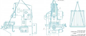
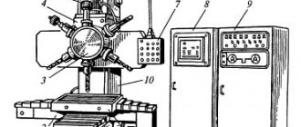
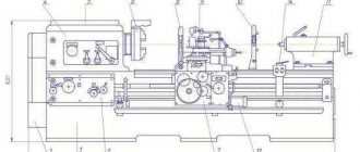
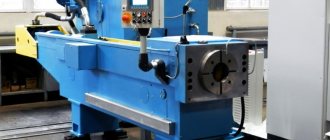
Slotting machines (Fig. 1) are designed for mechanical processing of metals by cutting using special cutters. This group of machines is highly specialized due to the limited operations that can be performed on standard equipment.
Figure 1. Slotting machine.
Figure 1. Slotting machine.
Information about the manufacturer of the slotting machine machine 7A420
The developer and manufacturer of the 7A420 slotting machine is Saraktash Machine-Tool Building , Saraktash, Orenburg region.
Saraktash Machine Tool Plant was founded in 1941. Since the 70s, it has specialized in the development, production and supply of a wide range of hydraulic drives for industrial equipment, pumps, valve equipment, feeders, hydraulic distributors.
Machine tools produced by Saraktash Machine Tool Plant
- 7A412
slotting machine with mechanical drive Ø 360 - 7A420
slotting machine with mechanical drive Ø 500
Principle of operation
According to their purpose, slotting machines are divided into two types: standard and specialized. Standard slotting machines are universal units that can be used to carry out a wide variety of operations. Specialized devices are designed for processing complex parts - punches, gears, etc.
The machines are driven by a drive. It can be equipped with three different types of mechanisms:
- crank;
- hydraulic;
- with a rotating scene.
The main processing tool is a hollow metal cutter (chisel) with a square drill inside. It is mounted on a vertical moving slider. The carriage allows you to drill even very large grooves in the workpiece.
The operating principle of the slotting machine is dual-mode. In the case of a simple mode, processing is carried out by repeated contact of the cutter with the workpiece at different points of the same plane. For example, a series of parallel holes of the same diameter and depth is drilled. A machine with a simple operating mode can be made manually.
In complex mode, the workpiece is processed in different planes, with multiple rotations of the carriage with the cutter in different directions, at different angles. This way you can drill grooves and recesses in hard-to-reach places on the part. Units operating in complex or combined modes are manufactured only using professional equipment. It is almost impossible to make such an installation at home yourself.
7A420 mechanically driven slotting machine. Purpose and scope
Developer - Gomel Machine Tool Plant named after. S. M. Kirov.
The 7A420 slotting machine with a mechanical drive is designed for the production of keyways, splines and grooves on shaped and flat surfaces in small-scale and individual production, as well as in repair shops.
7A420 machine is designed for processing by chiselling flat and shaped surfaces, grooves and grooves in a variety of parts, as well as various types of dies installed directly on the table or in fixtures. The ability to rotate the frame with the cutter allows you to process inclined planes without changing the position of the part.
The table moves both manually and mechanically. The circular feed of the table makes it possible to process round parts and gears on the machine.
Features of the 7A420 slotting machine
7A420 machine is equipped with:
- rotating cutting head for chiselling at an angle of 90° in both directions,
- a device for tilting the cutter slide at an angle of up to 5° to the vertical plane for the manufacture of keyways in conical holes, as well as
- vertically adjustable cutter in the range of up to 265 mm
The machine is one of the models in the range of slotting machines. It is characterized by high performance, ease of management and maintenance, reliability and safety in operation. The machine is not built into an automatic line.
Roughness of the processed surface is not less than V 6
Machine accuracy class N
Basic technical data of the 7A420 slotting machine:
Manufacturer: Saraktash Machine Tool.
- The stroke length of the cutter is 20..200 mm
- Diameter of the working surface of the table - Ø 500 mm
- Number of double strokes per minute - 40..163
- Drive power - 3 kW
- Full machine weight - 2.0 t
The best wood slotting machines
These models are designed to work with soft materials. Wood slotting machines are widely used in carpentry shops, furniture factories, and in the production of windows and doors. With their help, you can select grooves, grooves, and sockets.
Griggio G 550 S
5
★★★★★
editorial assessment
100%
buyers recommend this product
The electric welded frame ensures the strength and stability of the machine when working in intensive mode. The front clamp reliably holds the workpiece during operation. The carriage and spindle head are made of cast iron and are highly durable.
The size of the desktop is 600x110 mm, the dimensions of the model are 1000x800x2100 mm. An automatic lubrication system and a chain tensioner simplify maintenance of the unit. The working surface can be rotated at an angle of up to 45° for ease of chiselling parts of complex structures.
Advantages:
- reliable fastening of the workpiece;
- convenient control;
- ease of maintenance;
- robust design.
Flaws:
- high price.
Griggio G 550 S is designed for horizontal or vertical chiselling of grooves for hinges, locks, and sashes. Used in medium and large-scale production of window blocks, furniture or doors.
Powermatic 230V 719T
5
★★★★★
editorial assessment
98%
buyers recommend this product
A spacious cabinet is included with the unit. The owner can store tools and other equipment necessary for work in it.
For quick commissioning and maintenance of the device, the kit also includes spare structural elements, flywheels, and mandrels for installing cutters of various diameters.
The spindle speed is 1400 rpm. The dimensions of the machine are 540x550x1880 mm, control is carried out using only two buttons. The depth of chiselling is adjustable by the operator, which guarantees the accuracy of processing parts. The end stop and axle travel limiters are also adjustable.
Advantages:
- rich equipment;
- ease of maintenance;
- long service life;
- small dimensions;
- long control handle.
Flaws:
- complex installation.
Powermatic 719T is recommended for making grooves at angles up to 35°. An excellent choice for professional use.
Jet 719 AS 708572KM
4.8
★★★★★
editorial assessment
93%
buyers recommend this product
One of the design features is a long hand lever with rack and pinion gear and gas stop. With its help, the operator can not be distracted from the workpiece while making grooves. Special rotating handwheels and a graduated scale provide quick adjustment of the surface position.
The motor power is 1300 W, the spindle speed is 1450 rpm. The fixing device allows you to securely fasten the part before starting. The depth stop and travel limiters along the axes can be adjusted. The table is made of cast iron and equipped with a wooden overlay, which guarantees strength and resistance to heavy loads.
Advantages:
- robust design;
- reliable fixation of the workpiece;
- stop adjustment;
- high performance;
- Ease of use.
Flaws:
- narrow table.
Jet 719 AS is designed for making longitudinal and transverse grooves. A reliable solution for professional use.
Encore Corvette-92
4.8
★★★★★
editorial assessment
90%
buyers recommend this product
The unit is equipped with a vice with a quick-release mechanism and clamps. Their use facilitates the installation of the workpiece, ensures reliable fastening and increases the accuracy of processing.
Feed pulleys with rotating handles ensure easy table movement. A pneumatic shock absorber compensates for the weight of the moving headstock.
The motor power is 750 W, the working surface size is 400x150 mm. The model is equipped with a magnetic starter, the use of which eliminates the possibility of spontaneous activation during power outages. A special ruler makes it easier to control the distance between holes and the length of the selected groove.
Advantages:
- small dimensions;
- reliable fixation of the workpiece;
- careful processing;
- long service life;
- ease of installation.
Flaws:
- small chiseling depth.
The Encore Corvette-92 is worth purchasing for installation in a garage or home workshop. An affordable choice for processing wood and plastic products.
READ ALSO
12 best hammer drills
FDB Maschinen MS361D
4.7
★★★★★
editorial assessment
87%
buyers recommend this product
This machine has a dovetail type slide equipped with a stroke adjustment mechanism. The absence of play ensures smoothness of both longitudinal and transverse movement of the work table. Clamps guarantee reliable fixation of the part in a horizontal or vertical plane.
The motor power is 550 W, the spindle speed is 2800 rpm. The sampling depth and longitudinal feed limiters ensure accurate and precise processing.
The unit is small in size and weighs only 62 kg. The simplicity of the design facilitates maintenance and repair.
Advantages:
- convenient control;
- easy installation;
- accuracy of work;
- easy movement of the table;
- low price.
Flaws:
- high energy consumption.
FDB Maschinen MS361D will be useful in a home workshop or small production. Economical choice for making rectangular holes, pockets and slots.
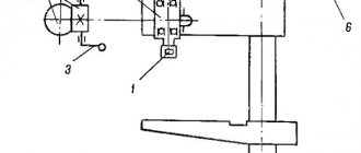
Location of the components of the 7A420 slotting machine
Location of the components of the 7a420 slotting machine
List of groups of components of the 7A420 slotting machine
- group No. 10 - bed
- Group No. 20 - gearbox
- group No. 21 - drive
- group No. 22 - pumping and lubricating
- group number 30 - dolbyak
- group No. 40 - rocker mechanism
- group No. 50 - feed box
- group No. 60 - table
- group No. 80 - electrical equipment
- group No. 90 - accessories
All groups of the machine are made in separate housings and installed on the machine, which facilitates their assembly during manufacture and repair. The pump and lubricator group is located inside the upper frame and installed on the gearbox.
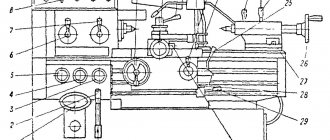
Location of controls for the 7A420 slotting machine
Location of controls for slotting machine 7a420
Specification of controls for slotting machine 7A420
- Flywheel for manual movement of the cutter
- Levers for turning the clutch on and off
- Button for enabling accelerated table movement
- Start button
- Stop button
- Square for setting the stroke length of the cutter
- Handle for setting the number of double strokes of the cutter
- Cutter clamp handle
- Square for changing the angle of the cutter
- Handwheel for manual longitudinal feed of the table
- Handwheel for manual circular table feed
- Handwheel for manual table cross feed
- Handle for turning on the table circular feed
- Cutter tilt adjustment nut
- Local lighting button
- Table feed switching drum
- Table feed cut-off drum
- Table fixing handle
- Table feed reversal handle
- Button for rapid oil supply to the cutter guides
Machine design 7a420
The model 7A420 slotting machine consists of the following groups (Fig. 5): group No. 10 - bed, group No. 20 - gearbox; group No. 21—drive; group No. 22 - pumping and lubricating; group No. 30 - dolbyak; group No. 40 - rocker mechanism; group No. 50 - feed box; group No. 60 - table; group No. 80 - electrical equipment; group No. 90 - accessories (not shown in the figure) -
All groups of the machine are made in separate housings and installed on the machine, which facilitates their assembly during manufacture and repair. The pump and lubricator group is located inside the upper frame and installed on the gearbox.
Bed (group 10)
The bed consists of two parts: upper and lower. A frame with a cutter is installed between the two cheeks of the upper frame. On the sides of the frame there are plates on which the drive and gearbox are installed.
The inside of the frame also serves as an oil bath. The upper part of the frame is installed on the lower part and secured with bolts. Two electric motors are installed at the bottom of the frame, and an electrical cabinet is attached to the outer rear side. A table with a slide is mounted on prismatic guides. A feed box is installed on the right side of the lower part of the bed.
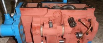
Gearbox (group 20)
Gearbox of slotting machine 7a420
The gearbox has four shafts mounted on rolling bearings in a separate housing (Fig. 6). On shaft 1, connected to the drive shaft by an eccentric coupling 11, a movable block of gears 10-9 and fixed gears 7 and 8 are mounted.
Shaft II carries a movable block of gears 5-4 and fixed gears 3 and 2.
By switching the block gear through gear 1, connected to the rocker gear, the latter is provided with four different rotation speeds.
On roller III there is gear 15, connected to the rocker gear, and gear 16, which through gear 17 transmits movement to shaft IV and then to the feed box.
All speeds are switched by one handle 12 through shifters 13 and 14.
The longitudinal play of the shafts is regulated by compensating rings and clamping nuts.
Flywheel 6 serves to drive shaft II into rotation. When there is a need to manually move the cutter. To do this, you need to pull the flywheel towards you and engage the splines of the flywheel and shaft.
Drive (Group 21)
From an individual electric motor, through V-belts, rotation is transmitted to drive pulley 2 (Fig. 7), which is mounted on two tapered ball bearings pressed onto the housing bushing.
A disc clutch 1 is mounted on the outer splined end of the hollow shaft V. A rod 8 runs inside the hollow shaft, the threaded end of which is connected to the clutch 7, and the other end to the cone brake clutch 6.
The braking device allows you to quickly stop the drive. Fork 9, sitting on rod 4, imparts movement to the brake clutch, and, consequently, to the clutch mechanism.
The drive is turned on and off using interlocked handles 3 and 5, which makes it easier to control the machine.
Pump and lubricator group (group 22)
Eccentric coupling 4 (Fig. serves as a drive for the plunger pump.
The lubrication mechanism is mounted on the gearbox housing and placed inside the upper part of the frame. Plunger pump 1 supplies oil through filter 5 to oil distributor 3 and the gearbox and rocker mechanism are generously lubricated.
Through lubricator 2, metering lubrication of the nut, linkage of the rocker mechanism and the guides of the cutter is carried out. The lubrication system is adjusted through the rear window of the upper part of the frame.
Dolbyak (group 30)
The cutter 6 (Fig. 9) is a box-shaped body that slides along the guides of the frame 5. A cutting head 1 is installed on the bottom of the cutter, which rotates 90° in both directions. The degrees are counted using the vernier on the neck of the cutter. The cutting head is secured with a cone 2, which is tightened with a bolt 3. To set the chiselling point, it is necessary to loosen the tightening of the handle 4 with the handle placed on the square 13, and rotate the screw VI through the gears 12 and 9. After installing the cutter to the required height relative to the table, handle 4 is tightened again.
On screw VI sits a nut 7, which is connected through an earring 8 to the rocker mechanism. The machine can process inclined planes up to 5° by installing the cutter frame, for which it is necessary to loosen the stop 10 and rotate the telescopic screw nut 11.
The countdown is carried out using a scale on the frame. After setting the angle of inclination of the cutter, stop 10 is tightened again.
Rocker mechanism (group 40)
The rocker mechanism is designed to convert the rotational movement of the rocker gear into the reciprocating movement of the cutter (Fig. 10). Housing 5, mounted in the gearbox, rotating on two tapered roller bearings, carries gear 11.
On the guides of the body 5 there is a finger 4, on which a stone 3 is placed. The slide 2 is mounted in the upper part of the frame on axis 1 and is connected at one end to the earring 8 (see Fig. 9).
When the rocker gear rotates, the finger of the stone 4 makes a rotational movement around the axis of the body 5. The stone 3, rotating together with the finger, slides along the guides in the groove of the rocker and causes it to swing on the axis, this is how the reciprocating movement of the cutter occurs.
The stroke length of the cutter is set by rotating shaft VIII with a crank handle placed on a square. Through gears 10, 9, 8 and 7, rotation is transmitted to screw VII.
The finger moves with the help of a screw, and as the distance between the axes of finger 4 and body 5 changes, the stroke length of the cutter will change. The counting is carried out using vernier 6.
Feed box (group 50)
The feed box (Fig. 11) carries out longitudinal, transverse and circular feeds of the table and its accelerated movement. Roller IX is connected to the gearbox through articulated couplings and, through gears 5 and 15, imparts rotational motion to shaft X with a set of eccentric cams, allowing twelve different feeds. The roller of the lever 14 in contact with the cams makes an oscillatory movement, and, consequently, the gear sector 16, sitting motionless at the other end of the shaft XI, also oscillates, being in engagement with the gear 17. A lever 4 is mounted on the gear 17, carrying a pawl. 3, which allows intermittent feeding through the ratchet wheel 18. Then, through the reversing mechanism (gears 9, 10, 7, the movement is transmitted to gear 1 and through safety clutch 2 to the feed shaft XVIII.
Lever 14 moves along the axis of shaft XI with the help of translation 20, mounted on shaft 19, on which the feed shift drum sits. The feed amount is set according to the vernier of drum 16 (see Fig. 27). Eccentric 6 is used to turn off the feed.
Accelerated movement is carried out from an individual electric motor through pulley 12 and overrunning clutch 11. Reversal is carried out by turning on the claw clutch 13 on shaft XII with gears 10, 9.
In case of overloads, to prevent breakdowns, the box has a release clutch 2, which depresses the spring and leaves the cam engagement with gear 1. In these cases, it is necessary to turn off the machine, remove the load, and then continue working again.
Table (group 60)
The machine table is mounted on the lower part of the frame and consists of a lower slide 2 (Fig. 12), an upper slide and a rotary round table 5. The machine table has longitudinal, transverse and circular feeds, both manual and mechanical, which include handwheels 1, 6, respectively and 7.
To enable mechanical feed, the handwheels are pushed away from themselves to the clutch of the cam clutches; for manual feed, the handwheels are pushed towards themselves. All movements from the feed box to the table are communicated through shaft XVIII.
Circular and transverse movements are communicated through an apron with gears 14, 13, 19, 18, 17, 16 and 15. Longitudinal movements are communicated through an apron with gears 23, 22, 21 and 20. From shaft XVII through gears 8,9,12, 10 and a folding worm 11, which meshes with gear 4, imparts a circular motion to the table. All three table movements have twelve feeds and rapid movement. On the circular table 5 there is a fixing device with twelve points.
Activate accelerated movement with a button, reversing with the feed reverse handle (see Fig. 27).
Principle of operation and device selection
The main movement that the mechanism makes is reciprocal and forward. The device operates in vertical planes, but moves in a straight line, just like planing machines.
The most important element of the device is the slotting cutter, which is fixed in the slide. The table, with the workpiece fixed on its surface, carries out the feed.
The reciprocal and translational actions of the machine occur periodically, while the slotting cutter can move in both linear and circular movements.
Both homemade and professional machines have two chiselling modes: simple and complex. A simple type of chiselling is done point-blank, and the cutter runs over some space and creates a series of holes of the same size and shape.
The second mode of operation of the device includes impact passing at an angle with inclined surfaces - a homemade machine may not be able to cope with this and a hydraulic one will be needed.
This device is needed to process hard-to-reach surfaces of parts. These include surfaces located inside the part used in different types of production, or partially hidden.
A homemade device is suitable for private workshops or small-scale production, but in large-scale industry they use complicated processing methods and therefore use a special device for working with CNC metal.
In private production, a workshop or a service center, the machine is most often used to work with metals (non-ferrous and ferrous), cast iron and other metal alloys.
The most used and popular type of machine is the “GD” model. You can find series 200, 500, etc. - they all belong to this type of device and meet its characteristics.
A more advanced model of the slotting machine: “S315TGI”, it is characterized by greater functionality compared to the previous one or home-made device models.
This machine can work with shaped, flat, conical and cylindrical surfaces. It also allows you to make splines, make recesses, grooves, grooves and holes.
The model supports several channel profiles, which are built individually based on the type of device setup you choose.
When purchasing, you need to take into account several factors so that the device serves you for a long time and does not require repairs soon. First of all, you need to know the permitted height of parts for the device.
This figure may vary and depends on what type of surface (internal or external) needs to be processed.
You also need to look at the declared power of the machine, the size of the cutter and the possibilities of its adjustment, find out whether the device has a transverse and longitudinal stroke, and what the permissible angle of inclination is.
The quality of operation of the device is also affected by the speed at which the working tool moves. To make the machine stable, buy products with a massive stand - then it will be easier to work with.
You need to be careful when choosing the size of the table itself, because... The ease of working with the device also depends on it.
In addition to the main parts, you need to find out if there is any additional equipment that is included in the device set.
The weight and size of the table are important not only as a factor in the convenience of working with the machine, but also for its placement in a workshop or other selected room - the device must be freely accessible, so do not choose too large models for small rooms.
Metal slotting machines are devices designed for processing metal workpieces. Devices of this type are highly specialized machines and are capable of creating elements of various types by removing metal. Metal slotting machines can be purchased at the appropriate store or made by yourself. You can find instructions on how to create a device yourself in this article.
Technical characteristics of the 7A420 slotting machine
| Parameter name | 7A420 | 7402 |
| Basic machine parameters | ||
| Machine accuracy class | N | N |
| Maximum stroke of the cutter, mm | 20..200 | 20..200 |
| Limits of double strokes per minute (number of speeds) | 40..163 (4) | 32..202 (6) |
| Table diameter, mm | 500 | 500 |
| Distance from the table plane to the cutter guides, mm | 320 | 320 |
| Distance from the cutter to the frame (reach), mm | 480 | 450 |
| Adjustment adjustment of the cutter stroke, mm | 264 | 265 |
| Maximum cutting force, kN (kgf) | 15,0 (1500) | 15,0 (1500) |
| Maximum longitudinal table movements, mm | 500 | 500 |
| Maximum table transverse movements, mm | 400 | 400 |
| The largest movements of the table are circular, degrees | 360° | 360° |
| Price for dividing the longitudinal movement dial, mm | 0,05 | 0,05 |
| Transverse movement dial division price, mm | 0,05 | 0,05 |
| Price for dividing the circular movement dial, min | 2′ | 2′ |
| Longitudinal movement per flywheel revolution, mm | 6 | 6 |
| Transverse movement per flywheel revolution, mm | 6 | 6 |
| Circular movement per flywheel revolution, deg | 4° | 4° |
| Feed limits for one double stroke, longitudinal, mm (number of steps) | 0,1..1,2 (12) | 0,1..1,2 (12) |
| Transverse feed limits for one double stroke, (number of steps) mm | 0,1..1,2 (12) | 0,1..1,2 (12) |
| Feed limits for one double stroke circular, (number of steps) deg | 0,064..0,81 (12) | 0,066..0,799 (12) |
| Speed of rapid table movement longitudinal, mm/min | 1,8 | |
| Speed of rapid table movement transverse, mm/min | 1,8 | |
| Speed of rapid table movement circular, deg/sec | 3,4 | |
| Maximum angle of inclination of the cutter, degrees | 5° from the bed | 5° from the bed |
| Maximum angle of rotation of the tool holder head, degrees | ±90° | ±90° |
| The largest section of the cutter (height x width), mm | 32 x 20 | 32 x 20 |
| Electrical equipment. Drive unit | ||
| Number of electric motors on the machine | 2 | 2 |
| Main motion drive electric motor, kW (rpm) | 2,8 | 1,8; 3,0; 3,6 (710, 1460, 2920) |
| Electric motor for rapid table movement, kW (rpm) | 1,1 (1400) | 1,1 (1400) |
| Total power of all electric motors, kW | 4,7 | |
| Dimensions and weight of the machine | ||
| Machine dimensions (length width height), mm | 2300 x 1270 x 2175 | 1900 x 1270 x 2175 |
| Machine weight, kg | 2000 | 2000 |
- Slotting machine 7A420. Manual, 1968
- Kopylov R.B. Working on planing and slotting machines, 1975
- Petrukha P.G. Cutting of structural materials, cutting tools and machines, 1974
- Yakovtsev A.D. Working on planing and slotting machines, 1966
Bibliography:
Related Links. Additional Information
- Hydraulic drive of the 7M430 slotting machine. Typical faults
- Repair of hydraulic systems of metal-cutting machines
- Designations of hydraulic circuits of metal-cutting machines
- Classification of metal-cutting machines
- Selecting the right metalworking machine
- Testing and checking metal-cutting machines for accuracy
- Directory of factories producing metal-cutting machines
- Manufacturers of metal-cutting machines
- Directory of slotting machines
- Articles on the topic
Home About the company News Articles Price list Contacts Reference information Interesting video KPO woodworking machines Manufacturers
Kinds
Slotting machines are classified according to many criteria, but they are all somewhat similar, which was the reason for the creation of two main groups:
- in production conditions where the level of productivity plays an important role, a centrifugal woodworking slotting machine is used. It is often large in size and capable of creating a wide variety of grooves
- For a home workshop, a manual slotting machine or wood slotting drill is more suitable. This device operates on the principle of a milling cutter.
The household slotting device has a simple design and low cost. The industrial slotting machine is most often used only in large manufacturing plants due to its high price. Such equipment is designed for mass production. organizations that conduct mass production.
Let's consider the design of the machine using the example of a slotting chain device.
Basic moments:
- a special chain is the main structural element. It has a very large number of individual links connected to each other in a hinged manner. It is worth noting that each link is represented by a milling tooth, sharpened in a special way
- the main components of the device are necessary for transmitting movement and adjusting the processing procedure. This chain is pulled onto a special guide bar along which it moves. The teeth remove wood to form a groove and chips.
Note that in the manufacturing process of different models, almost the same slotting machine design is used. It is quite simple, somewhat similar to a drilling machine. The main element of the entire machine is the bed, because all other components are mounted on it. A movable support equipped with an electric motor and a table is fixed to the frame. Please note that the unit on which the workpiece is fastened is a table with a clamping element. The electric motor is responsible for transmitting rotation using a belt. Belt drives are used in the production process of various structures.
However, there are also models that work differently. The support with the cutting element is stationary, while the table can move through a mechanical or hydraulic drive. Household models often do not have a drive. The video will tell you in more detail about what kind of slotting machines there are.
Different types of slotting machines can have a vertical or horizontal arrangement of the cutting tool. The most popular is the horizontal wood slotting machine, since it is compact and easy to work with.