Cold stamping (CS) is considered the most advanced metal forming technique. Its qualified application makes it possible to obtain products of various shapes and sizes. What is important is that products made using this technology are distinguished by the accuracy of their geometric parameters and the high quality of the formed surface, and therefore do not require further refinement. The cold stamping process can be easily automated, which makes it possible to manufacture products using it with high productivity.
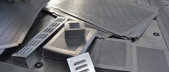
These parts were produced by cold stamping
Features of stamping technology
Stamping is a complex technological process during which a metal workpiece is subjected to mechanical pressure, which leads to its plastic deformation. To perform such processing, special equipment is used. As a result of its influence on the material, workpieces of the required shape and size are obtained. The main raw material used for stamping is sheet metal of different thicknesses.
This processing method is divided into two types:
Cold stamped parts
- hot. Involves preheating of workpieces;
- cold. The workpieces are not heated before stamping.
Hot stamping is used for materials that do not have high ductility. This processing method is most often used in the production of workpieces in small batches from metal sheets having a thickness of 5 mm. When manufacturing parts, it becomes necessary to apply large tolerances. When they cool, warping and other negative processes occur that affect the size of the future workpiece.
When performing cold stamping, special equipment is used. During processing, the material is further strengthened, but its plasticity is lost. To prevent increased fragility of finished products, they are additionally subjected to recrystallization annealing.
Features of cold stamping technology
Cold stamping technology involves processing workpieces by changing their shape and size, but maintaining other geometric characteristics.
Strips, tape or sheets obtained from alloyed low-carbon steels are used as raw materials to obtain the necessary products. Alloys of aluminum, copper, brass, magnesium, titanium or other highly plastic compounds can be used. This is due to the fact that such materials are easily deformed.
List of operations performed during stamping
During the process of cold metal stamping, various operations are performed that help give the product the required characteristics. They can be separative and shape-changing. In the first case, the surface of the material is partially separated along the specified contour. Separation operations include:
- cutting Separating part of the workpiece along a straight or figured line using a press in the form of scissors;
- punching Performed to create a hole of the required shape and size in a part;
- cutting down The finished part looks like a closed contour.
Classification of basic stamping operations
Form-changing operations during stamping involve changing the shape or size of a sheet metal workpiece by moving its parts in a certain way. In this case, physical destruction of the part does not occur. The most common form-changing operations include:
- hood. Refers to volumetric stamping, with the help of which hollow parts of various shapes are produced (cone, cylinder, hemisphere, cube);
- flexible. With the help of such stamping, the bend of the sheet material is given almost any shape;
- relief molding. Implies local changes while maintaining the configuration of the workpiece itself;
- cold landing. Allows you to obtain a part of the required length with an increase in its diameter.
It is possible to stamp using a combined method, which involves dividing and shaping the part.
Additional operations performed during the stamping process
Annealing steel for stamping
During the process of cold stamping of metal, it can be subjected to some auxiliary operations that improve the performance of the resulting products. These include annealing and etching. With their help, mechanical characteristics are improved and the service life of parts is increased.
To improve the wear resistance of the metal, it is treated with special protective coatings.
During die stamping, a list of operations is performed to improve the mechanical characteristics of metal products:
- preliminary heat treatment of metal to reduce its strength;
- preparing the surface for major work;
- direct metal processing.
Types of cold stamping
In order to change the original geometric parameters of a metal sheet in several directions, cold die stamping is used. In order not to increase the resistance of the metal and, accordingly, not to reduce its fluidity, such a technological operation is performed at a temperature that does not exceed forging.
Cutting out washers is the simplest example of cold stamping
Using this technology, which requires the use of special equipment, products are manufactured with increased precision, without such defects as hot cracks, scratches, burrs and risks, areas subject to metal shrinkage. However, due to the fact that the stamping press used to perform volumetric stamping is forced to overcome the enormous resistance of unheated metal, it is problematic to obtain parts of complex configurations with its help. In such cases, it is better to use hot rather than cold stamping.
Another type of metal forming, during which the workpieces are not preheated, is cold sheet stamping. When performing processing using this method, the workpiece can be a sheet, tape or strip made of metal. The thickness of the walls of the workpiece when using this technology practically does not change, and spatial products can only be obtained from ductile metals.
Cold stamping equipment
Cold stamping of metal is carried out using special equipment. To process parts, a stamping press is used, which can be mechanical (eccentric, with a crank mechanism) or hydraulic.
Features of the design and operation of a crank-type press
General view of the crank press
Sheet stamping, which involves cutting, drawing, and punching metal, is carried out on crank-type presses. It has an electric drive.
The main operating element of the press is the crank shaft. It moves by transmitting rotation from the flywheel of the electric motor through a gear mechanism. As a result, the crank slider performs a reciprocating action, which initiates stamping.
The main components of the crank press are made of high-strength steel. They are further strengthened, which gives the equipment increased rigidity.
Hydraulic press device
Hydraulic presses are primarily used for volumetric stamping using the punching method.
Hydraulic press device
The operating principle of such equipment is quite simple:
- the operation of the press is ensured by the pressure of the liquid, which is placed in two special containers with pistons;
- the tanks are connected to each other using a tube;
- the pressure that arises during the movement of liquid through the press containers is transferred to the slide;
- Due to the displacement of the slider, cold stamping is carried out.
Content
Introduction Section One Cold Sheet Forming Technology
Chapter I. Separating operations 1. Sheet metal cutting with scissors 2. Sheet metal cutting force with scissors 3. Sheet metal cutting with dies 4. Cutting force during cutting and punching 5. Clearances between the die and the punch 6. Finish cutting, punching and cutting off 7. Cleaning stamping 8. Cutting with rubber and polyurethane 9. Trimming hollow parts
Chapter II. Bending 10. The process of bending sheet metal 11. Neutral layer 12. The magnitude of deformations and the minimum permissible bending radii 13. Determination of the dimensions of workpieces during bending 14. Elastic springing during bending 15. Tensile bending 16. Bending moments and bending forces 17. Structural and technological bending elements 18. Bending of pipes and thin-walled profiles
Chapter III. Drawing 19. The process of drawing sheet metal 20. Determination of the size and shape of workpieces during drawing 21. Technological calculations during drawing and construction of the technological process 22. Determination of drawing and clamping forces 23. Work and speed of drawing 24. Radiuses of curvature and clearances during drawing 25. Lubrication during drawing 26. Hardening of metal and annealing during drawing 27. Special methods of drawing 28. Drawing of refractory metals and alloys
Chapter IV. Sheet forming 29. Relief forming 30. Flanging 31. Stretching (expansion) 32. Swaging 33. Straightening and embossing 34. Cold extrusion of sheet metal
Chapter V. Stamping of non-metallic materials 35. The main types of non-metallic materials used in cold stamping 36. Reacting and cutting parts from non-metallic materials 37. Bending of non-metallic materials 38. Drawing and forming of non-metallic materials
Chapter VI. Special types of sheet metal forming 39. Pulse high-speed stamping methods 40. Profiling of strip and sheet metal 41. Rotary extrusion (pressing and rolling processes) 42. Rolling and bending operations
Section two Fundamentals of the development of technological processes for cold sheet stamping
Chapter I. Manufacturability of sheet stamped parts 1. Technological requirements for the design of stamped parts 2. methods for improving the technological quality of sheet stamped parts and ways to save metal
Chapter II. Development of technological processes for cold sheet stamping 3. Contents and order of development of technological processes 4. Cutting of material and size of jumpers 5. Fundamentals of constructing technological processes for cold sheet stamping 6. Technological processes and dies used in small-scale production 7. Accuracy of stamped sheet parts
Chapter III. Selection of press equipment 8. Basic principles and parameters for selecting a press 9. Adjustment of presses and closed height of the press 10. Equipping presses with pneumatic cushions and buffers 11. Modern types of presses for sheet metal stamping 12. Layout and maintenance of the workplace
Section three Typical designs of dies, their assemblies and parts
Chapter I. Tile diagrams of dies 1. Technological types of dies 2. Structural and operational types of dies
Chapter II. Typical units and parts of dies 3. Typical parts of dies 4. Typical structural units and parts of dies 5. Typical technological units and parts of dies 6. Manufacturing accuracy and cleanliness of processing of parts of dies 7. Materials for parts of dies 8. Plastic dies 9. Durability of dies
Chapter III. Typical designs of cold sheet stamping dies 10. Typical designs of separation dies (simple, sequential and combined action) 11. Typical designs of forming dies (bending, drawing, combined)
Chapter IV. Design and calculations of dies for strength and rigidity 12. Procedure and stages of design 13. Manufacturability of the design of assemblies and parts of dies 14. Determination of the center of pressure of the die 15. Calculations of dies parts for strength and rigidity 16. Closed height of the die and press
Section four
Mechanization and automation of cold sheet stamping processes
Chapter I. Methods of automation and mechanization of sheet metal stamping production 1. Basic methods of automation 2. Integrated mechanization and automation
Chapter II. Devices for mechanization and automation of stamping 3. Mechanization and automation of supply of material and workpieces 4. Mechanization and automation of removal of parts and waste 5. Automation of counting, stacking and weighing of stamped parts 6. Automation of control, blocking and control of the stamping process 7. Automatic stamping lines
Section five
Main materials used in cold sheet stamping
Chapter I. Mechanical and technological properties of sheet materials 1. Mechanical properties revealed by tensile testing of sheet metals 2. Anisotropy of sheet metals 3. Technological properties and testing of sheet metals 4. Instructions for the technological use of sheet materials
Chapter II. Characteristics of sheet materials 5. Basic materials used in cold sheet stamping 6. Mechanical properties of basic sheet metals
Literature collection
Subject index
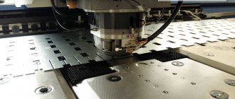
How are dies made for cold stamping?
Cold sheet metal stamping technology
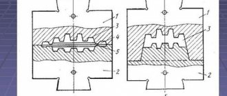
A stamp is a specific type of equipment that is actively used in the sheet stamping process. It directly affects the material, deforming it. After processing, the metal acquires the same shape as that characteristic of the working part of the stamp. This tool is installed on special hammers and presses that drive it.
The stamp consists of two parts - a matrix and a punch. The last element is fixed on a special slider, due to which the tool moves. Metal deformation occurs at the moment the punch is pressed against the matrix.
Stages of production of cold stamping dies
High demands are placed on the process of creating stamp sketches and their actual production. The correct formation of the products themselves and their quality depend on the quality of the resulting equipment. Typically, stamp production occurs in the following sequence:
Cold die forging
- A sketch of the stamp is drawn up taking into account all the requirements presented.
- Using a special computer program, a stamp diagram is created.
- The rationality of the resulting equipment is determined, and if necessary, the sketch is adjusted.
- The places where holes of the required size and shape will be formed in the future are determined.
- After approval of the drawings, the production of the stamp begins immediately.
Workpieces made of metal will be correctly processed by cold stamping if all the equipment is selected effectively. Stamps are one of the main elements influencing the quality of the work performed. In their production, modern CNC equipment is used, which allows for the necessary quality control.
DIES FOR COLD STAMPING. TYPICAL UNITS AND PARTS
Most dies have a certain number of standard parts that are similar in purpose and design.To simplify the design, manufacture, operation, and repair of die equipment, standard units and parts are normalized. Normalization reduces the number of worn-out stamp parts , expands the possibilities of interchangeability of parts, reduces the need for the number of stamps used in production , increases the reliability of their operation, and reduces the cost of stamping equipment. when developing dies, manufacturing and repairing them . The development of a set of mechanical engineering standards for stamping equipment has made it possible to sharply reduce the range of components and parts of dies and to produce dies in which up to 80% of the parts are normalized. The most widely used types of assemblies and parts of dies for cold stamping (provided for by mechanical engineering standards): DIE BLOCKS Die blocks are sets of upper plates and lower die bases connected by guide devices (columns, strips).
- with two guide columns,
- with diagonal column arrangement
- rear or axial arrangement of speakers
For stamping large, complex and precise parts, die blocks are made on three and four columns. To regrind the die without disassembly, die blocks with counter-pressing of the columns - one column is pressed into the lower plate, the other into the upper one. For work in large-scale and mass production on high-speed presses, universal die blocks for separating dies on columns with ball guides. Compared to sliding guides, ball guides have an easier movement, they do not heat up at high stamping speeds, they hardly wear out and provide greater directional accuracy. Ball guides, after being lubricated during assembly of the block, do not require additional lubrication for several months of operation. The lower and upper plates of the die blocks are cast from cast iron or steel. The guide columns and die bushings are made of low-carbon steel, case-hardened and hardened. To ensure independence and accuracy of the stamp operation from the condition of the press slide guides, in stamp blocks with ball guides, a shank with a “floating” fastening to the top plate is used. Die packages are upper and lower sets of die parts. They consist of rectangular (or round) steel plates that carry a punch, die, puller and other parts. Stamp packages are stamp blanks. Selected according to the size of the parts, they make it possible to quickly create any stamp based on a normalized block, making a punch, a matrix and a puller of the desired profile for it. Packages of dividing dies: cutting, punching, sequential action and the like are manufactured with fixed pullers and with an upper clamp. SHANKS FOR DIES. For regular and block dies intended for separation operations, standard shanks with a collar are used. This type of shank is pressed into a pre-bored hole in the top plate. For dies with special die centering accuracy , the shank, after being pressed into the plate, is additionally ground in assembled form. For drawing and bending dies with guide columns, threaded shanks , and in large dies, threaded shanks with a shoulder are used. In large dies with guide columns, where the shank is used for central installation, or in dies where, for design reasons, other types of shanks cannot be used, special shank designs are used. For screw fastening of the punch of drawing dies, shanks with fastening of the punch in the shank are used. When cutting thin-sheet materials during fine and precise stamping in cutting dies of combined action and in dies with carbide punches and dies , as well as in die blocks with ball guides, self-aligning (“floating”) shanks with a spherical liner are used. For heavy duty work in bending dies, fork shanks are used. When installing dies on presses that have different hole sizes in the slide for the die shank , adapter shanks or adapter split bushings are used. PUNCHES FOR DIES. Cold forming dies use standard punches of various types.
- Shape: round and profile
- by design - solid and composite,
- according to the method of fastening in the upper plate of the die - non-separable and quick-change.
Non-separable punches are secured by pressing into the upper plate of the die with subsequent riveting of the non-working end or using a collar on the non-working end. Both the riveting and the shoulder are necessary to hold the punch in the top plate of the die during the reverse stroke of the press ram. Quick-change punches have a cylindrical non-working part and are secured with a ball that fits into the punch recess. They are replaced without removing the stamp from the press. Profile punches are secured by riveting the non-working part or using screws and pins. In Fig. 65, a-k show the main types of round and profile punches. Round punches of type A, held by a riveting head, are used for punching holes with a diameter of up to 12 mm, especially when several punching punches are located close together, when retention by a shoulder cannot be used of type B, held by a shoulder, is used for punching holes. The cylindrical extension part k of these punches is designed to fit into the hole of the die guide plate. A type B punch with a collar is designed for punching large holes and cutting out parts along the contour. When the punch diameter is more than 45 mm, a recess is made at its end to reduce the grinding surface during sharpening. The type G punch is quick-change, held by a ball with a spring. A punch is used when punching a large number of holes in material up to 3 mm thick. Replacement is carried out by pressing the ball through the hole. A punch of a similar design (type D) is used for heavy punching work and in large dies. The ball is held in place by a pressure screw. Profile punches come in four main types. The type e punch, held by a rivet, is used for cutting out small and medium-sized profile parts. To cut out parts of medium size and complex shapes, type Z punches are made, having a flange with which they are attached to the top plate of the die with screws and pins. The type 3 punch consists of two parts: the working part and the insert. It is used to save tool steel when cutting parts of large dimensions, but of simple configuration. Composite punch type is used for cutting out parts of large dimensions and complex configurations. It consists of separate cutting sections fitted to each other and mounted on the top plate of the die. The sections are secured with screws and pins. For punches with a complex working profile of type K, a landing part of a simple shape is provided. The largest dimensions of the landing part must coincide with the overall dimensions of the working contour of the punch. MATRIXES FOR STAMPS. In dies for cold stamping, standard dies are used :
- by design - solid and composite,
- in shape - round, rectangular or profile,
- according to the method of fastening - non-removable or quick-change.
Non-separable matrices are secured by pressing or screwing to the plate with screws (bolts). Quick-change dies are secured with screws or a ball. The common design and technological element of the matrices of cutting and punching dies is the shape of their working profile. Type A round cutting dies are used for cutting round workpieces. For simple, sequential and combined cutting (or punching) of medium-sized parts, type B dies are the most common. When cutting out parts of complex shapes, cutting out large parts or small-width parts with large lengths and sharp corners, type B split dies are used. Cutting the matrix facilitates its production and finishing, and eliminates warping during hardening. For cutting out parts of large dimensions and complex shapes, composite dies of type g are used, consisting of separate sections fitted to each other and mounted on the bottom plate of the die. Work on such matrices is carried out with reverse ejection of the cut-out part. Punching dies for multi-punch dies are most often made in the form of replaceable cylindrical inserts. Smooth matrices (type d) and matrices with a collar (type e) are secured by pressing into the matrix plate. They are used only for punching round holes. Quick-change cylindrical dies (type g), held by a ball with a pressure screw, are used for holes with a diameter of up to 30 mm. The profile elements of the working hole of the matrix are selected depending on the thickness of the stamped material. When punching several closely spaced holes with a diameter of up to 8 mm, matrices with a profile of type Z are used. The same holes are made for cutting out simple contours (type l). For matrices with a figured contour, a hole shape of type i or m is used. A profile of type k with an increased height of the working conical hole or with a cone along the entire height is used for matrices of increased durability with small part sizes. For dies with reverse ejection of parts (mainly in combined-action dies), a profile of type n is used. PULLERS FOR DIES. Depending on the design of the die , the size of the punch, and the thickness of the material being stamped, punching and punching die removers may be designed to remove parts, to remove strip waste from punches, or to give precise guidance to punches. The exact direction of the punch in the puller is necessary to ensure that the gap between the die and the punch is uniform on all sides. In this case, the gap between the punch and the puller should be no more than the gap between the punch and the matrix and is usually taken equal to 0.8 of the latter’s value. Fixed and movable pullers are used. Fixed pullers are used in punching dies working from a strip to fail, and in punching dies, if during stamping it is not necessary to press the workpiece against the die and if the puller itself does not interfere with inserting the workpiece into the die and removing the part from the die. When it is necessary to give direction to the punch, only stationary pullers are used. Precise direction of the punch in the puller is recommended for use in dies that do not have guide columns, in multi-punch dies with different punch sizes, in dies with thin punches and in dies with a top clamp. In movable pullers, the movement and the necessary clamping force are provided by springs, rubber buffers or pneumatic and mechanical devices of dies and presses. Movable pullers are used in combined dies of combined action and with an upper clamp. The puller shown in diagram d is also a clamp for the part and at the same time a clamp for the internal contour of the part. Diagrams f, g, h, and show various design options for movable pullers. GUIDE BARS FOR DIES. The slats impart direction to the strip (tape) as it moves. If it is necessary to press the strip to one side of the guide bar, side clamps are mounted along with the bar. The gaps between the walls of the guide bars and the strip are important, as they determine the accuracy of the material being directed into the die. The size of the gap depends on the width of the strip at a certain thickness and ranges from 0.5 mm (with a width of up to 50 mm and a thickness of up to 1 mm) to 2.5 mm (with a width of more than 200 mm and a thickness of more than 5 mm). For stamps with step knives, the distance between the slats is determined by calculation taking into account the width of the part of the material cut by the knives. On the exit side of the strip, the distance between the guide bars is taken equal to the distance between the stepping knives. For stamping parts from thin materials, elongated guide bars are used, equipped with a device for pressing the strip or tape as it moves between the walls of the bars. STOPS FOR DIES. The stops are designed to limit the feed of the strip into the die. The main types of stops: Type a - permanent mushroom stop is used in dies with a fixed puller when manually feeding material; type b - constant hook-shaped - has the same purpose, but is used in cases where the seating part of the stop needs to be removed from the cutting edge of the matrix. For combined-action dies, “sinking” stops with a spring or stops with a rubber liner are used. In cutting dies with a fixed puller, when cutting out narrow parts (from 6 to 20 mm) with a thickness of at least 0.8 mm, spring movable return stops of type B are used. For sequential action dies, when installing the strip on the first pass, preliminary side clamps are made with or without a spring. Cutting dies and combined dies of sequential action when stamping small and medium-sized parts from material with a thickness of more than 0.5 mm are equipped with automatic stops. This stop is connected to the upper plate of the die and is driven by the working stroke of the press slide. Catchers. In combined sequential action dies, the final position of the strip after punching the first hole is fixed by catchers, which eliminate feed errors and ensure the correct position of the punched holes. CATCHERS AND RETAINERS FOR DIES. Catchers and clamps:
- round catchers for different hole diameters,
- pin retainer,
- strip retainer
For multi-row stamping, two catchers are installed. The entry (catching) part of the catcher must have a pointed shape, and the fixing part must be cylindrical, square or profile in accordance with the shape of the hole of the stamped part. Retainers. To fix previously cut workpieces, various clamps are used, the design of which depends on the shape of the workpiece. Methods of fixation are used along the outer contour of the workpiece and along the contour of the hole. In some cases, workpieces are fixed, as indicated earlier, using technological holes specially punched for this purpose. WEDGE DEVICES FOR DIES. Wedge devices. In multi-operational dies, wedge punching devices are used to punch holes in the side walls of hollow or bent parts, allowing one or more holes to be punched or punching to be performed simultaneously with other operations. Wedge devices are also used in dies when it is necessary to bend the side flanges of flanged parts. The literature used by the manufacture of stamps, press forms and devices edition of the 2nd, processed and supplemented by the Academic Council of the State Committee of the Council of the USSR of the USSR for Professional and Technical Education as a textbook for vocational schools Moscow “Higher School” 1974 Author: Ip Demidenko author: https://www.nncm.ru 03/08/2010