The abbreviation KGShP refers to a crank-type hot stamping press. The exceptionally high power of individual models of such equipment makes it the optimal choice for enterprises involved in the processing of scrap metal.
Hot stamping crank press with a nominal force of 14,000 tf. Used for hot stamping of crankshafts weighing up to 200 kg as part of a modern robotic line
The use of CGSP, in particular, makes it possible to successfully solve such a pressing problem for these enterprises as packaging scrap metals with low ductility (aluminum and titanium alloys, bronze, etc.). Meanwhile, purchasing a press of this type is an unaffordable luxury for the vast majority of such enterprises. The main area of application of CGShP, which are presented on the modern market in a wide variety of modifications, is to equip production facilities that produce their products in large, medium and small batches.
In the video below you can see the K8540 crank hot forging press in action.
Information about the manufacturer of the single crank press K2019
The K2019 press was produced by the Kursk Forging and Pressing Equipment Plant , founded in 1943.
Currently, the K2019 press is produced by:
- Dolina, PJSC Kuvandyk plant KPO, Kuvandyk, Orenburg region.
- PressMash, LLC Machine Tool Association, Moscow
Machine tools produced by the Kursk Forging and Press Equipment Plant
- K2019
open single-crank press for sheet stamping 80 kN - KD2114
single-crank open press for sheet metal stamping 25 kN - KD2118
single-crank open press for sheet metal stamping 63 kN - KD2318
single-crank open press for sheet metal stamping 63 kN
DIY electro-hydraulic press - Do it yourself
Equipment such as an electro-hydraulic press, due to its versatility and high efficiency, is actively used both in large manufacturing enterprises and in small workshops, as well as at car service stations. Using a hydraulic press equipped with an electric drive, you can solve many technical problems, which include:
- pressing, pressing out of gears, bearings and shafts;
- stamping, straightening and bending of metal products;
- pressing of products made from wood shavings, plastic and metal.
The electro-hydraulic press R-342M is intended for performing work on pressing, straightening and pressing in repair shops
A serial electro-hydraulic press will be quite expensive, but you don’t have to buy it, but make it yourself.
Installation of the hydraulic cylinder on the bed
The process of installing a hydraulic cylinder on the frame of a homemade hydraulic press is carried out in a certain sequence.
1. Adjustment of hydraulic cylinder, flange and plate
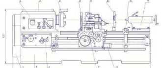
The body of the hydraulic cylinder, so that it can be placed in the inner part of the flange, is turned on a lathe.
The flange, which can be made from a car hub, is also processed on a lathe.
In order to make a hole in a metal plate that will be used as a base for installing a hydraulic cylinder, it is necessary to weld a round boss to it. With the help of the latter, such a plate will be fixed in the lathe chuck.
20 mm thick plate with a welded boss in the center
After the hole in the slab is bored out, it is welded to the beams of the base frame.
The flange, in which the mounting hole has already been prepared, is put on the hydraulic cylinder and welded in a circle.
Flange welded to hydraulic cylinder
It is very important that the flange and hydraulic cylinder are connected as smoothly as possible; for this, the adjacent surface of the flange must be machined on a lathe. 2. Installation of upper beams and hydraulic cylinder
The plate, which is already connected to the beams, is installed on the frame and connected to it by welding.
Through the holes on the mounting part of the flange, holes are drilled in the plate, which are necessary for placing the mounting bolts.
The installation of the upper beam is carried out strictly perpendicular to the supports
The hydraulic cylinder should not be attached to only one point, so it is necessary to make another flange, put it on the top of the cylinder and weld it to the beams.
Installing the Top Flange
T-beams installed in the upper part of the frame are connected to each other by welding.
3. Installation of the frame and oil station
In order for the hydraulic press you have made to fully function, you need to install an oil station on it and connect it with a hydraulic cylinder using hoses.
Installation of a frame and a two-flow hydraulic station delivering a pressure of 700 bar
Thus, it is not difficult to make a hydraulic press with an electric drive with your own hands. At the same time, you will have at your disposal equipment that can solve many technical problems.
Making a hydraulic press with your own hands
The hydraulic press has become widespread. This device is used in many auto repair shops for pressing and unpressing bearings, various gears and shafts. In a home workshop, a manual hydraulic press, made by hand, is very often used, since installations made in industrial conditions have a high cost.
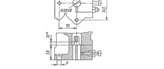
K2019 Dimensions of the crank press die plate
Dimensions of the crank press die plate K2019
Diagram of permissible forces of a single-crank press by 2019
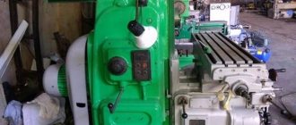
K2019 image of single crank press
Photo of single crank press k2019
Photo of single crank press k2019
Photo of single crank press k2019
Design and principle of operation
The hot stamping press is designed for processing workpieces at temperatures up to 1200°C. At the same time, there are some features in the design of the equipment:
- For medium and low rated power, asynchronous electric motors are installed. At high power, the manufacturer uses synchronous units that develop a force of up to 31.5 MN.
- The rotational motion is transmitted through wedge-shaped belts.
- The main shaft that receives the movement is installed in bearing supports. On one side there is a flywheel, and on the other end there is a speed conversion mechanism for the eccentric shaft.
- On the eccentric shaft, on one side, band brakes are installed, and on the other, a clutch for engagement, which contains several friction discs.
- A brake and clutch control system is mounted on the press.
- The machine is equipped with guides for the slider.
- The open height is adjusted by a wedge that is installed on the table.
- The bed consists of several elements that are connected by heated pins.
- The fixed part of the press is mounted on the work table.
- The lubrication and monitoring system for equipment operation is installed by the manufacturer.
Principle of operation:
- The electric motor transmits movement to the flywheel and intermediate shaft.
- The clutch is activated when the set number of revolutions per minute is reached, air is supplied to it under pressure and the eccentric shaft is connected to the connecting rod.
- The brake located at the end of the main shaft is automatically released.
- The slider begins forward movement with return.
- The moving part of the die, thanks to the slider, performs the hot pressing operation.
- When the slider moves upward, the finished product is automatically ejected.
Devices for securing the workpiece and automating the process can be additionally added to the design.
Industrial equipment (Photo: Instagram / kubanzheldormash)
This is interesting: Chemical metallization: technology, implementation at home
Location of the main components of the K2019 single-crank press
Location of the main components of a single-crank press by 2019
- Bed K2019-11-001
- Drive K2019-21-001
- Eccentric shaft K2019-23-001
- Command apparatus - K2019-24-001
- Installation of clutch-brake K2019-26-001
- Slider K2019-31-001
- Air duct KE2118.01-41-001
- Drive guard K2019-71-001
- Command apparatus fencing - KE2114.01-72-001
- Work area fencing -
- Electrical equipment K2019-91-001
- Push-button control station KE2114.01-92-00
- Flywheel -
- Pneumatic blower
Design
Features of performing technological operations at high (up to 1000...1200
0
C) temperatures determined the following composition of components of such equipment:
- AC asynchronous electric motor (for CGPS with particularly high forces exceeding 31.5 MN, synchronous motors and even DC drives are used as a drive).
- Powerful V-belt drive.
- A receiving shaft rotating in plain bearings, on which a flywheel is mounted on one side, and on the other, an open reduction gear that transmits torque to the eccentric shaft.
- An eccentric shaft, on one end of which a band brake is mounted, and on the other, a friction multi-plate clutch.
- The activation system (clutch, brake), with which the flywheel braking unit is also structurally connected.
- Crank mechanism with additional upper slider guides. The movable half of the stamp is attached to the lower end of the slide.
- A wedge mechanism for adjusting the closed height of the press, which is installed on the press table.
- A rigid frame assembled from individual elements and fastened together with tie rods. They are hot tightened to create the required level of compressive stress.
- The press table to which the stationary part of the die is attached.
- Lubrication and control systems for hot stamping presses. The latter necessarily includes elements of control and diagnostic equipment.
KSHP
KGS can operate either autonomously or as part of specialized stamping lines.
The operating features of the CGShP, in comparison with conventional crank equipment, are considered to be:
- High speed to ensure minimum workpiece cooling/waste time;
- High drive power, which is associated with the need to ensure increased energy consumption during a fairly short technological cycle of hot stamping;
- The presence of upper and lower ejectors (in the slider and table, respectively), the use of which prevents hot workpieces from sticking in the die;
- Non-adjustable connecting rod, which makes it more rigid and durable;
- Increased number of clutch discs.
On modern CGSH designs, instead of the traditional crank-and-rod mechanism, a crank-wedge mechanism is installed, which is advantageously distinguished by increased stamping accuracy and less wear of contact surfaces.
Location of controls for single crank press K2019
Location of controls for single crank press K2019
- Pedal
- Input switch
- Operating mode switch
- Counter
- Light signaling
- Local lighting switch
- Button "Stop continuous strokes"
- "General stop" button
- Button "Start electric motor"
- Buttons "Slider stroke" (Two-handed activation)
Electrical control circuit for the PVG-8-2-0 press - Physics
Equipment such as an electro-hydraulic press, due to its versatility and high efficiency, is actively used both in large manufacturing enterprises and in small workshops, as well as at car service stations. Using a hydraulic press equipped with an electric drive, you can solve many technical problems, which include:
- pressing, pressing out of gears, bearings and shafts;
- stamping, straightening and bending of metal products;
- pressing of products made from wood shavings, plastic and metal.
The electro-hydraulic press R-342M is intended for performing work on pressing, straightening and pressing in repair shops
A serial electro-hydraulic press will be quite expensive, but you don’t have to buy it, but make it yourself.
Principle of operation
Hydraulic presses equipped with an electric drive are capable of developing enormous forces, which is explained by the design features of such equipment. The principle by which the electro-hydraulic press works is as follows.
- An electrically powered motor drives a hydraulic pump.
- The hydraulic pump, in turn, maintains the pressure of the working fluid in the first chamber of the press.
- The piston of the first chamber transmits pressure to the second cylinder of the electro-hydraulic press, where it increases significantly.
- The pressure created in the second chamber of the hydraulic cylinder is transmitted directly to the working body of the electrohydraulic press.
Diagram of a frame-type hydraulic press (click to enlarge)
Thus, the amount of working pressure that will be imparted to the working body of an electro-hydraulic press depends on how different the areas of the pistons in its two cylinders are.
The operation of the press, the main working body of which is a hydraulic pump, is based on Pascal's law, which states that the force acting on any area is transmitted throughout the entire volume, and it has equal value in all directions.
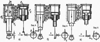
Crank press diagram
Let's consider the crank press diagram shown in Figure 17, which provides four operating modes.
Electric motor M,
activated by contactor K, rotates constantly and, through a mechanical transmission, drives the driving part of the friction clutch, which is controlled by an electromagnet EM, acting on the pneumatic system switches.
The engine operates from a network with a voltage of 380 V, the coils of the contactor K and the electromagnet are powered from the secondary winding of the transformer Tr with a voltage of 127 V, the control circuit and local lighting lamp LO - 36 V, signal lamps 1LS, 2LS - 6 V.
By creating a galvanic isolation between the network and control circuits, the transformer eliminates the appearance of parasitic circuits in emergency modes, leading to spontaneous switching on of the press.
Using the PR switch, the operating diagram of which is shown in Figure 18, four operating modes are provided:
1) automatic operation on continuous strokes;
2) single moves with two-handed control;
3) single strokes controlled by an electric contact pedal;
4) adjustment or jog mode.
As can be seen from the diagram in Figure 18, in the adjustment mode, contact PR1 is closed and the EM electromagnet and, accordingly, the friction clutch are turned on when the KnPm button is pressed and the RE relay is turned on.
During automatic operation, when PR2 and PRZ are closed, the clutch is also engaged by pressing KnPm with the VZR contact closed, when the protective grill enclosing the working area is lowered.
In the single stroke mode, when PR2 and PR4 are closed, after switching on the contactor K, through PR4 and the opening contacts of the electric contact pedal VPE and the two-handed control buttons 1Kn and 2Kn, the coil of the blocking relay RB is energized, which, when turned on through the contacts KA2, powers itself.
Figure 17 — Diagram of a crank press
| Mode pins | Automatic operation | Single moves when controlled from | Setup mode | |
| buttons | pedals | |||
| PR1 | — | — | — | X |
| PR2 | X | X | X | — |
| PR3 | X | — | — | — |
| PR4 | — | X | X | — |
| PR5 | — | X | — | — |
| PR6 | — | — | X | — |
Figure 18 — Operation diagram of the PR switch
With two-handed control (PR5 is closed), pressing the 1Kn and 2Kn buttons through PR5 and the closed contact P5 energizes the RE relay coil, which turns on the electromagnet of the EM pneumatic switch. The friction clutch engages and the crank shaft begins to rotate.
At the bottom dead center, contact KA1 closes and, through the PRZ relay RE, powers itself up. The buttons can be released, because The slide rises and is safe for your hands. Near the top dead center, contacts KA1 and KA2 open and the slider stops.
If the buttons are kept pressed all the time, the NC contacts 1KN and 2KN will be open. Near the top dead center, the KA2 contacts open and the RE relay disappears, turning off the RE with its opening contacts and the slider stops.
To get a new press stroke, you need to release the buttons and then press them again. This prevents the slider from moving again (doubling strokes).
When controlled from an electric contact pedal, opening contacts PR5 and closing PR6 introduces RE coils and VPE pedal contacts into the circuit instead of 1Kn and 2Kn. The press is turned on and the slider moves downwards when the grid is lowered and the B3P contacts are closed. Otherwise, the operation of the circuit is similar to that in two-handed control mode.
Control questions:
1 Option
1. What are the requirements for the electric drive and electrical equipment of crank presses?
2. Describe the operation of the crank press circuit in single stroke mode when controlled by an electric contact pedal.
Option 2
1. What control devices are used in presses?
2. Give a general description of the crank press circuit?
Option 3
1. Under what conditions are electric drives with asynchronous motors used?
2. Describe the operation of the crank press circuit in continuous stroke mode.
4 Option
1. Under what conditions are electric drives with synchronous motors used?
2. Describe the operation of the crank press circuit in single stroke mode with two-handed control.
5 Option
1. What are the features of using SD to drive presses?
2. What operating modes of the press are provided by the control circuit?
6 Option
1. What measures ensure safe servicing of presses?
2. What do lamps 1LS and 2LS signal?
7 Option
1. What is the purpose and operating principle of a cam control device?
2. In what mode is it possible to turn on the friction clutch without turning on the electric motor?
8 Option
1. What do the load diagrams of the torque of AD and SD look like when they are used in press drives?
2. What is the purpose of the KA2 contacts in the crank press circuit?
Types and scope of application
Both home-made and mass-produced hydraulic presses are classified according to several parameters:
- sizes;
- maximum force produced;
- design features of the equipment (in particular, the height of the rod).
The most powerful are hydraulic presses related to floor-type equipment.
A hydraulic floor-type press, distinguished by significant dimensions, is capable of creating pressure at one point, the value of which can reach tens of megapascals.
The scope of use of equipment of this type, which can be equipped with additional devices, is quite wide. Floor hydraulic presses are necessary to solve such technical problems as:
- installation and removal of bushings, shafts, bearings;
- pipe bending;
- pressing of products made from various materials, including metal.
Some models of floor-type electro-hydraulic presses provide the ability to change the height of the work table.
Electro-hydraulic press 2135-1M, force 40 tons
Tabletop hydraulic presses, along with their small size, are characterized by less power. The pressure created by such equipment, installed on a desktop or workbench, rarely reaches 20 tons. The compactness of tabletop electro-hydraulic presses allows them to be used in small automobile and home workshops.
An important parameter of electrohydraulic presses, in addition to the force they are capable of creating, is the height of their rod. This parameter, in particular, determines what size parts the equipment can work with. If for tabletop presses this parameter can reach 100 mm, then for floor-standing models it reaches half a meter.
Due to their versatility, electrohydraulic presses are used in many fields of activity. Such areas of activity, in particular, are mechanical engineering, woodworking and food industries. However, most often such equipment can be found at vehicle repair stations.
Using it, you can successfully solve not only all of the above technical problems, but also straighten dents and other damage to the car body.
Unlike pneumatic equipment, the use of which requires a rather complex pneumatic system, a hydraulic press with an electric drive can simply be connected to an electrical power supply, and it will function normally.
Why is a press needed in a home workshop?
At home, a low-power hydraulic press can be an indispensable assistant during car repairs and other types of work. To press out a silent block or bearing and press a new one in its place, you do not need to turn to a car service for help and pay a lot of money.
Using a press, you can make straightening with your own hands, bend a metal blank, firmly glue two parts together under pressure, compress cans, plastic bottles, cardboard or paper, squeeze out moisture or oil. Purchasing a factory-made press will cost a considerable amount.
But you can make this tool yourself , spending only on the required materials. Moreover, it is possible to make a device that is adapted and adapted to specific needs, taking into account the necessary tasks.
Since a homemade hydraulic press will in any case need a certain place, if you don’t have a workshop, you can install it in the garage.
How to make your own hydraulic press with electric drive
Serial hydraulic presses with electric drive are quite expensive, so it makes sense to think about how to make an electro-hydraulic press with your own hands. To do this you will need the following tools and equipment:
- welding machine;
- lathe;
- drilling machine;
- Bulgarian;
- electric drill.
This press will be able to produce a maximum pressure of 35 tons
The supporting structure of the electro-hydraulic press, which is subjected to the main mechanical loads, is the frame, the strength of which should be given special attention. A T-beam made of metal of such thickness that it can withstand the loads created by a hydraulic press without bending is well suited for these purposes.
Press frame made of I-beam
Structurally, the frame of a homemade electro-hydraulic press is a U-shaped frame, welded from T-beams and installed on a base, for the manufacture of which thinner channels and angles can be used. In the middle part of such a frame (along its height), a working platform is welded into it, for the manufacture of which thick-walled channels are used.
Kinematic diagram of single-crank press K2019
Kinematic diagram of the K2019 single-crank press
List of kinematic diagram elements
- Electric motor
- Drive pulley
- Drive flywheel
- Clutch-brake
- Eccentric shaft
- screw
- Eccentric bushing
- connecting rod
- Adjustment screw
- Crawler
- Ejector stop
- Ejector bar
- Air supply head
- Bearing
- Bearing
- Bearing
Ladder logic
As I already said, any circuit on a relay corresponds to a circuit on logical elements. AND, OR, NOT, Delay Line, Trigger (memory cell) - all this is implemented on a relay.
Here is an interesting video that talks about this in detail:
I recommend the site pro-rza.ru for those who work with relay circuits (as well as program algorithms) professionally, and not just based on intuition). You can also find a lot of interesting information on the topic if you enter the query “relay logic circuits” in Yandex.
Description of the press K2019
bed
Press bed fig. 10 is cast iron, box-shaped, absorbs all the forces generated during stamping, and is mounted on two posts 8 and 10 using four pins.
In the upper part of the frame 2, in the cups 11 and 12, there are rolling bearings 13, which serve as support for the eccentric shaft.
On top, on the bevel of the frame 2, there is a plate for the sub-motor plate on which the electric motor is installed.
In front, on specially treated areas of the frame, prismatic adjustable guides 17 for the slide are attached.
The guides are adjusted with screws using threaded connections 14, 15 and 16.
The front part of the frame is closed by door 3.
A stamping plate 6 is fixed on the working plane of the table.
For work without failure, holes are provided on the table and plate.
An inclined slide 7 is attached to the lower part of the frame to remove stamped parts or waste.
Drive unit
Drive (see kinematic diagram in Fig. 9).
The slider stroke is adjusted by rotating the eccentric sleeve 2, which is connected to shaft 1 through a gear and is disengaged by rotating the nut 3.
After setting the required stroke value of the slider, the eccentric sleeve is brought into engagement with the eccentric shaft by rotating nut 3, which is locked with screw 6.
The required amount of slider stroke is set on scale 4 using pointer 5.
Installing the clutch-brake (Fig. 12)
The clutch-brake installation consists of a flywheel 1-3 and a clutch-brake 5-14, mounted on the eccentric shaft 4 of the press, an air supply head 15-18, mounted on the clutch-brake and a bracket 21, connected by pins 20 to the clutch-brake and mounted on press bed.
The flywheel 1 is supported by radial ball bearings 2, mounted on a sleeve 3, which in turn is mounted on an eccentric shaft 4.
The rigidly interlocked multi-disc friction clutch-brake with pneumatic activation consists of the following parts:
- driving - driving disks 5 of the clutch with friction linings;
- driven - hub 6 with a fixedly attached piston 7, cylinder 8 moving along the axis, intermediate disks 9, support nuts 10 installed along the threads of hub 6 and piston 7, pressure disk 11 mounted rigidly on cylinder 8;
- brake - brake disc 12 with friction linings.
As friction linings 5 and 12 wear, the gap “a” increases, which causes increased knocking when the clutch is engaged and air consumption increases. To adjust this gap, use split nuts 10, which are secured against unscrewing with nuts 13.
The unified air supply head consists of a housing 15, a fitting 16, rubber seals 17 located between them and radial ball bearings 18.
The clutch brake works as follows:
Compressed air through the air supply head 15-18, piston 7, hub 6 enters the pneumatic chamber “B” and moves the cylinder 8 along the axis of the eccentric shaft towards the clutch, which clamps the drive disks 5 of the clutch, which are constantly connected to the flywheel through fingers 19, ensuring the transmission of torque moment through the hub b onto the eccentric shaft 4.
At the moment of braking of the eccentric shaft 4, compressed air from the pneumatic chamber is released into the atmosphere through the air supply head 15-18, while the cylinder 8, under the influence of the springs 14, returns towards the brake and clamps the brake disc 18, sitting on the fingers 20, fixed in the bracket 21, which is rigidly associated with the bed.
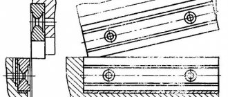
Slider (Fig. 13)
The slider is the working part of the press to which the upper part of the die is attached.
The press slide 13 is box-shaped with prismatic double-sided guides. The slider is attached to the eccentric shaft by means of an adjusting screw 5 and a detachable connecting rod 4 in the housing and cover of which there are bronze sleeve bearings 2 and 3, covering the eccentric sleeve.
The total gap between the guides of the slider and the frame should be in the range of 0.04-0.08 mm. The gap in the ball joint should be no more than 0.015 mm. The gap between the bronze bushings of the connecting rod and the eccentric bushing is no more than 0.1 mm.
The ball head of the adjusting screw 5, the lower support 10 and the floating liner 8 are placed in the slider 12. After adjusting the gap in the ball joint, the nut 8, screwed into the slider 12, is locked with a screw 17.
The ball joint is supported by a shear safety washer 13, designed to withstand destruction when the press is overloaded. When cutting off the safety washer, use screw 17 to unlock nut 18, unscrew it 1.5-2 turns, lift the connecting rod with the adjusting screw, turning the press flywheel in the “Manual crank” mode, replace safety washer 13 by removing the cover on the window in the front of the slider , tighten nut 18 and lock it with screw 17.
The size of the die space is adjusted by rotating the adjusting screw by its hexagon; the set size of the die space is fixed by locking bushings 20, which are tightened by a screw with a lock nut 19.
The lower limit of die space adjustment is limited by clamp 23.
The amount of adjustment is determined by ruler 6.
At the bottom of the slide there is a hole for the shank of the upper die plate.
The shank is fastened with clamp 17 using two studs with nuts. Locking screw 15 serves for additional fixation of the stamp shank, as well as for repelling the clamp when removing the stamp.
In the groove of the slider there is an ejector rocker, spring-loaded with two clamps.
Command apparatus. (Fig. 14)
The command device is designed to switch current in the electrical control circuits of the press and control the operation of the pneumatic blower.
The command device is installed on the left end of the eccentric shaft. Aluminum disks 1, 2, 3 are fixed to the sleeve 4. Contactless switches 8, 9 and 10 type BVK 201-24 are installed on bracket 7, fixed to the frame.
- BVK (SQ1), switched by disk 2, controls the solenoid valve of the U7122A pneumatic distributor;
- BVK (SQ2), switched by disk 1, controls another electromagnetic valve of the dual three-line pneumatic distributor (stopping the TDC slide);
- BVK (SQ3) blocks the downward movement of the slider when turned on two-handed (when the slider does not reach BDC, releasing the two-handed turn-on buttons causes the slider to stop).
Description of the press
The operation of the press is described in words like this: The engine with the flywheel rotates constantly. When the pedal (or button) is pressed, a pneumatic clutch is activated, through which the rotation of the flywheel is transmitted through the crank to the press block. This block, with a punch or cutter installed on it, squeezes out the metal or cuts out the required parts.
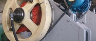
Flywheel:
Press flywheel. The hose in which the air operates the coupling is visible
Have you seen the operation of a steam locomotive, where the longitudinal movement back and forth is converted into rotational movement of the wheel? Now, the same thing happens in this press, only in reverse - the rotational movement is transformed into an up and down movement.
The position of the flywheel to stop it (that is, to turn off the clutch electromagnet) is determined using a non-contact sensor BVK201:
Non-contact sensor for determining the angular position of the press flywheel
Here is a picture explaining the operation of this sensor:
Position sensor operation
The starting position is shown. The sensor is active, i.e. its contacts are closed. When the activator rotates at the end of the cycle, it falls into the slot and is deactivated. Next, inertia is important, thanks to which the activator rotates a little more so that the sensor becomes active again. This inertia is adjusted by pressing the clutch.
I needed to implement this algorithm in a real circuit.
On my blog there are also descriptions of the operating principles and electrical circuits of other presses - hydraulic and pneumatic presses. I recommend.
Nameplate:
Nameplate press KD 2122K force 16 tons
Compressed air with a pressure of at least 6 kgf/cm2 is constantly supplied to the press to operate the clutch.
There are instructions and diagrams on the Internet for this and similar presses, the circuit is very complex, with transistors, with many functions and settings. As a rule, the scheme quickly breaks down, and craftsmen (like me) convert it to a simplified version. What is the article about?
The work of the press can be seen in the video at the end of the article.
Electrical equipment. General information
Electrical diagram of the single-crank press K2019
The electrical equipment used on the press has the following composition and characteristics:
- main drive electric motor - asynchronous three-phase alternating current with a supply voltage of 380 V;
- electro-pneumatic valves УV1, УV2 in the pneumatic distributor У7122А for 24 V DC;
- control cabinet.
The description of the operation of electrical equipment is indicated in the passport for the control cabinet.
Locks
The electrical circuits of the press and control cabinet provide the following interlocks:
- Zero blocking;
- blocking of pneumatic valves;
- blocking the doors of the frame;
- flywheel guard window blocking;
- air pressure switch;
- two-hand control;
- braking angle;
- control valves.
Supplying voltage to the press circuit does not cause spontaneous switching on of electrical devices. This is achieved by inserting the closing contact of the KM magnetic starter into the circuit of its own coil.
Locking pneumatic valves
When one of the pneumatic valves of the U7122A pneumatic distributor is blocked, the microswitch SQ11 or SQ12 is activated and turns off the electric motor and the press clutch.
Lock screen protector
When operating with a pedal, turning on the press clutch is possible only when the screen is closed (the limit switch is pressed in the “Single stroke” mode).
When working with buttons SB3 and SB4 in the “Continuous strokes” mode, the clutch can only be engaged when the screen is closed (the limit switch is pressed in the “Continuous strokes” mode).
Bed door lock
When the frame door is opened, the limit switch SQ15 is released and the electric motor and press clutch are switched off by the normally open contact.
Flywheel guard window lock
When the flywheel guard window is opened, the limit switch is released and the electric motor and press clutch are switched off using a normally open contact.
Air pressure switch blocking
When the air pressure in the system drops, the SP relay is activated and, with its normally open contact, turns off the drive motor and the press clutch, and the red warning light on the control cabinet lights up
Blocking control channels and command device failure
Each valve of the dual pneumatic distributor is controlled from an independent control element of the command apparatus via an independent circuit. If one of the control channels or command apparatus fails, one of the pneumatic valves of the U7122A pneumatic distributor does not operate. Microswitch SQ11 or SQ12 is activated and turns off the electric motor and the press clutch.
Making a diagram of the press
The simplest scheme that implements the desired algorithm may look like this:
The simplest diagram of a crank press
What does it remind you of? Yes, this is a classic self-retaining circuit, which is widely used to start electric motors. I decided not to indicate the neutral wire of the sensor so as not to clutter the diagram. I did not show the power, emergency and supply circuits - I have already written on this issue on the blog more than once.
The sensor contacts are equivalent to the “Stop” button, SB is a pedal, or 2 consecutive buttons on the panel. Relay KA1 has 2 groups of contacts - one for self-retaining, the other for turning on the electromagnet of the EM pneumatic valve.
The operation of a self-retaining circuit can be represented as a trigger, since when you briefly press Start, it is armed, i.e. Start = Set, Stop = Reset, KA1 = Q (output).
Pressing the SB pedal - the KA relay turns on, becomes self-retaining with its KA contacts, and remains on until the sensor opens the relay power circuit. This may take several strokes while the operator keeps the pedal pressed. When the pedal is depressed, the shock cycle will end at the top point, at the point where the sensor crosses zero.
When a full revolution is made, the sensor is deactivated, KA1 is turned off, the sensor activator rotates by inertia, and the sensor is activated so that a new pressing cycle can begin.
To prevent the valve from clicking when crossing zero, the KA1 contacts, which turn on the EM, can be bypassed with NO pedal contacts. Since the pedal, as a rule, does not have such contacts, you need to install an intermediate relay.
We continue to improve the scheme. In order to be able to continuously rotate the flywheel, the sensor can be bypassed. Then, when you briefly press the pedal, the EM will turn on and will remain on until the continuous mode is turned off:
Add switch SA1 to the circuit
This is the diagram I stopped at, only the sensor is connected via an intermediate relay.
There is also an interesting and necessary feature in the setup mode - when you turn on this manual mode, you can make the engine turn off. Then you can manually turn the flywheel in one direction or the other. This is useful in emergency situations when the press punch gets stuck in the down position. This can happen in different cases - jamming of a part, loss of air (more precisely, a decrease in pressure), and getting your hand under the press. Unfortunately, all these cases in mass production are not uncommon...
We continue to complicate things. We introduce another relay KA2, which allows you to work in the “1 press = 1 hit” mode. This mode is needed for safety and does not allow the operator to get too carried away.
Press diagram with a limit of 1 hit
The right side of the circuit remains absolutely the same, only the second NC contact of the pedal serves as an “anti-self-retaining” - if the pedal is pressed, it is open, and when the sensor opens at the end of the cycle, relay KA2 turns off.
This mode is turned off by toggle switch SA2.
Technical characteristics of the K2019 press
Technical characteristics of the single crank press K2019
Technical characteristics of the single crank press K2019
DIY hydraulic press with electric drive: components and assembly
Equipment such as an electro-hydraulic press, due to its versatility and high efficiency, is actively used both in large manufacturing enterprises and in small workshops, as well as at car service stations. Using a hydraulic press equipped with an electric drive, you can solve many technical problems, which include:
- pressing, pressing out of gears, bearings and shafts;
- stamping, straightening and bending of metal products;
- pressing of products made from wood shavings, plastic and metal.
The electro-hydraulic press R-342M is intended for performing work on pressing, straightening and pressing in repair shops
A serial electro-hydraulic press will be quite expensive, but you don’t have to buy it, but make it yourself.