12/08/2020 Author: VT-METALL
Issues discussed in the material:
- Main stages of welding
- Selection of welding technology
- Tools and equipment for pipe welding
- Preparation for longitudinal welding of pipes
- Preparing pipeline joints for welding
- Installations for longitudinal welding of pipes
- Welding longitudinal seams
- Safety rules for pipe welding
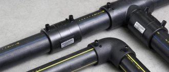
The “pipeline” age has arrived. In the 21st century, pipelines are being laid everywhere. They are used to transport oil and gas in all countries. They can be seamless and have a lot of advantages. However, their main disadvantage is the high cost of production.
As a result, in a number of market segments, despite their advantages, pipelines are inferior to welded pipes. Currently, up to half of all used products are welded. Such a significant volume of products consumed by the market requires careful consideration. It is necessary to understand what technologies are used in their manufacture, what types are distinguished, where they are successfully used, and much more. In this article we will focus on longitudinal pipe welding.
Main stages of welding
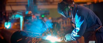
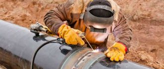
- Preparation. This stage is divided into two parts.
One includes organizing the work of a master welder, and the second involves preliminary preparation of the part. The first is crucial for the safety of the specialist and includes the mandatory use of a mask and gloves that protect hands and eyes from burns that are possible from splashes and their bright glow. Preliminary preparation of parts consists of cleaning them from adhering dirt, paint residues and rust. Not only the welding zone (joints of products), but also the areas around them are subject to treatment. For cleaning, use either sandpaper or a special brush with metal bristles. Without this process, there is a high probability of seam sections that have not been welded. - Welding process. At this stage, when making an arc connection, the most important thing is to hold the arc, and it does not matter how (manually or using an inverter) the connection is made. First, the electrode is activated, the arc is excited, and then a seam is formed, the type of which is chosen by the master himself. There are several factors that influence the processing technology and the method of working with the electrode: the material being welded, the location of the parts and the opinion of the specialist making the connection.
- Checking the quality of the seam. At the end of welding, the master removes the slag that covers the joint and checks the quality of the weld made.
When creating parts of gas and water pipelines, as well as other utility networks, the welding process occurs in the same way or with minor variations. The most important thing is the correct sequence of actions and the selection of suitable types of seams in different positions. If you know how to form them, you can achieve high quality welded joints.
Seam inspection and testing
All pipelines are subject to inspection of welded joints upon acceptance; the inspection includes the following control operations and types of tests of welded joints:
- visualization and measurements;
- steeloscopy of weld and pipe metal;
- determination of weld hardness;
- flaw detection by ultrasound and radiography;
- mechanical load testing;
- metallographic inspection;
- rolling a steel ball along the inner surface of the seam;
- Magnetic particle and capillary testing;
- pressure tests.
Rice. 8 Scheme of cutting samples for testing weld material
Checking the quality of welding of boilers and pipelines, which are not subject to the rules of the Gosgortekhnadzor of Russia, is carried out by visualization methods, measurements, ultrasound, radiography or mechanical tests, if other control methods are specified in SNiP.
When carrying out all types of welding work, one should be guided by the regulatory rules given in the relevant acts. For gas pipelines, their compliance is most important - this will ensure high quality welding of pipes in gas pipelines, where even minor errors can lead to dire consequences.
Selection of welding technology
According to the requirements of the RD regarding longitudinal seams, work should be carried out using automatic or manual arc welding, using non-consumable powder electrodes with a supply of carbon dioxide.
VT-metall offers services:
Work with pipes with a thickness of no more than 10 mm can be carried out by argon arc welding along the entire seam.
We recommend articles on metalworking
- Steel grades: classification and interpretation
- Aluminum grades and areas of their application
- Defects in metal products: causes and search methods
A pipeline made of carbon or alloy alloy with a diameter of no more than 150 mm and a wall thickness of maximum 8 mm can be welded with gas containing oxygen and acetylene.
The work site should be protected from wind and any precipitation. The master must work in protective glasses and gloves. To process surfaces, you need a hammer, a brush with metal bristles and a chisel.
Options, descriptions
| Cooling unit |
| Cold wire feed unit |
| Burner oscillation block |
| Arc Voltage Tracking (AVC) |
| Shielding gas supply device from below |
| Non-magnetic caliper |
| Device for supplying protective gas from above (protecting the cooling seam) |
| Variable height support for inserting bent sheets |
| Spacer plate for BRC and BRI |
| Device for welding conical products |
| Pneumatic retractable copper caliper |
| Automatic edge adjustment system |
Tools and equipment for pipe welding
Welding is considered perhaps the most common and simplest method of permanently connecting pipelines. It is carried out by experienced craftsmen using special equipment equipped with switches. These devices operate on electricity or gas. Their design may include equipment for socket welding. For domestic use, equipment is usually chosen with an inverter. To regulate the amount of energy and material consumed, control circuits are installed on it.
- Electrodes.
Electrodes are most often used in the welding process. To connect large diameter pipes, choose those that are coated with cellulose film. Fillet welds form rutile-coated products. Complex types of welding are performed using combined electrodes having a cellulose-rutile layer. The most common option has UONI 13/55 coverage. It is used for connecting pipes made of carbon and low-alloy steel. The unique composition of the electrodes contributes to the creation of extremely flexible seams that can withstand any type of load.
However, they also have a disadvantage - the need for pre-processing of the edges of the workpieces. If it is not carried out, pores may form in the structure of the seam, which make it unreliable. This is possible if there are residual moisture, rust and oils on the edge.
- Welders.
To carry out welding work, special equipment is required, primarily a transformer. Its design is simple and reliable, and its job is to convert the voltage in the electrical network. The principle of its operation is to transform the intermediate current between the turns of the winding. The efficiency of this device is high and is about 90%.
The rectifier has become a more advanced type of welding equipment. It includes a diode block, regulators, protection and triggering. If a transformer can be used to weld ferrous metal, then a rectifier can also be used to work with cast iron, stainless steel and non-ferrous metal. Its cost is low, and the quality of the seams is at a fairly high level.
Welding processes used:
— plasma welding — TIG argon arc welding (with an argon arc torch) — DC and AC welding — pulse welding — plasma soldering (with a wire feed unit) — TIG soldering (with a TIG torch)
Welding can be done without filler wire, as well as with the use of filler wire. It is also possible to equip it with a source for semi-automatic MIG/MAG welding according to the customer’s technical specifications. What are the differences and advantages of the plasma welding process, and how plasma welding works, read the article “Distinctive features of plasma welding”
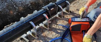
Preparation for longitudinal welding of pipes
Before starting longitudinal welding of pipes, be sure to check the equipment for serviceability and the presence of complete sets of elements, and evaluate the material of the pipes. Certificates and passports, which determine the chemical composition of steel, help to cope with the latter.
Before welding, joints are checked for:
- proportionality and shape, quality of surface preparation;
- quality of cleaning, both outside and inside;
- how smoothly the transitions from a small section to a large one are made;
- compliance of the wall thickness of the workpiece in the joint area with possible tolerances.
Electrodes, fluxes and additives are compared with the existing standard, they are checked based on the passports, certificates, and labels attached to the packages.
Electrodes intended for electric arc welding are tested. To do this, use samples of welds on brands, consisting of two shoulder straps, which are made of two plates. The connection is made in one pass in a ceiling location.
Technical characteristics of AWL FINGER M
| Model | AWL FORCE | AWL FORCE UNIT |
| Welding material thickness range | 0.8 - 10.0/ 12.0 mm | 0.8 - 10.0/ 12.0 mm |
| Product diameter for machine version 1100.M Min. / Max. | 120 / 1000 – 1500 mm | 120 / 5000 mm |
| Product diameter for machine version 2050.M Min. / Max. | 150 / 1000 – 1500 mm | 150 / 5000 mm |
| Product diameter for machine version 3050.M Min. / Max. | 180 / 1000 – 1500 mm | 180 / 5000 mm |
| Product length for machine version 1100.M | 50 – 1100 mm | 50 – 1100 mm |
| Product length for machine version 2050.M | 50 – 2050 mm | 50 – 2050 mm |
| Product length for machine version 3050.M | 50 – 3050 mm | 50 – 3050 mm |
| Specific clamping force | 0.35-350 N/mm² | 0.35-350 N/mm² |
| Welding speed range | 10 – 300 cm/min | 10 – 300 cm/min |
| Welding methods | TIG AC /DC, Plasma, Key Hole | |
| Using the maximum power current for welding | 450A DC / 330A AC/DC | |
| Power supply | 3×400 V | 3×400 V |
Preparing pipeline joints for welding
The end edges are processed using grinding machines, machines with a milling cutter, cutters and an abrasive wheel.
Pipes made of low-carbon material, as well as alloying additives, are prepared using arc and oxygen cutting, after which the surface is cleaned with abrasive or cutting tools.
If the pipeline has small ledges or irregularities that interfere with welding, then clean the joints with a file or an abrasive wheel. Work with care and avoid kinks and sharp corners.
Manufacturing of welded pipes
Home » Articles » Professionally about welding » Welding of various structuresWe recommend purchasing:
Installations for automatic welding of longitudinal seams of shells - in stock!
High performance, convenience, ease of operation and reliability in operation.
Welding screens and protective curtains are in stock!
Radiation protection when welding and cutting. Big choice. Delivery throughout Russia!
About 10% of the world's total steel production is spent on pipe production, and the share of welded pipe production accounts for more than half of the total production and continues to increase. Large diameter pipes (over 500 mm) are produced only welded. The serial nature of production, the large length of seams and the relatively simple shape of the product make it possible to effectively use advanced welding methods at very high speeds and completely mechanize the entire pipe manufacturing process.
The rapid development of pipeline transport requires a sharp increase in the production of large-diameter pipes made of low-alloy steels. Unlike the practice of the USA, where the pipeline network is constructed mainly from small-diameter pipes, in the USSR the main direction is the laying of gas pipelines with a diameter of 1420 mm with a working pressure of 7.5 MPa.
Pipes for main pipelines are made by submerged arc welding. The seam is placed either along a generatrix or in a spiral. Due to the limited width of the sheets, straight-seam pipes with a diameter of up to 820 mm are welded with one longitudinal seam, and with a larger diameter - two. Abroad, sheets of greater width are used, which makes it possible to produce pipes with a diameter of 1420 mm with one seam.
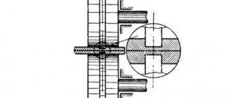
The Chelyabinsk Pipe Rolling Plant produces straight-seam pipes with a length of 12 m and a diameter of up to 1220 mm. Welding is performed on both sides, with the outer seam being laid first on a through-type mill. In front of the mill, the workpiece 2 is installed with the lifting turning rollers with the connector up along the axis of the guide knife 1 (Fig. 15.38).
While passing the mill, the pipe blank 2 is pushed onto the mandrel 5, suspended from the guide knife and supported by rollers on the inner surface of the pipe. The movement of the pipe is ensured by the driven horizontal rolls of the mill, and the gap between the edges as the workpiece moves narrows due to the lateral pressure of the vertical non-driven rolls and there is no gap in welding zone 3. The leakage of the weld pool is prevented by a caterpillar shoe 4 installed on the mandrel frame - a closed strip of hinged plates with copper plates. The movement of the pipe carries the tape, and under the weld pool there is always a fresh plate cooled by compressed air. Submerged arc welding is carried out with two arcs burning in one weld pool, which ensures good weld formation at a welding speed of 170-190 m/h and a wall thickness of 12 mm. To reduce the size of the crater, the end sections of welds with a length of 150-220 mm are performed with one arc while simultaneously reducing the welding speed. The losses for cutting the ends of the pipes in this case are small. The pipe enters the installation for welding the internal seam along a roller conveyor and is fed into movable cradles that lift and turn the pipe with the seam down. The cradles are mounted on a movable trolley, with the help of which the pipe is pushed onto a welding head attached to a 12 m long rod.
Pipes with two longitudinal seams are assembled from two preformed troughs, fed by the stacker to two parallel threads of the input roller conveyors of the assembly device. The edges of the workpieces are set in one horizontal plane using a leveling device, and in this position the troughs are fed by roller tables into the open assembly device (Fig. 15.39a).
The rods of the pneumatic cylinders 1 (Fig. 15.39,b), turning the levers 2, set the workpieces to the initial position for feeding into the welding machine. The gap between the workpieces is set by parts 3 and 4. The assembled pipe is fed into the welding mill by stop 6 of the chain pusher 5 at a speed slightly higher than the welding speed in order to catch up with the previous pipe (Fig. 15.39c). In this case, the guide knife of the mill falls into the gap between the upper edges of the troughs, directing the joint to the welding head. When the pipe is caught by the horizontal drive rolls of the welding mill, the chain pusher is turned off and returns to its original position. The workpiece welded with the first outer seam is turned with the connector up and is fed onto the roller conveyor to the mill for welding the second outer seam. Then, sequentially, similarly to single-seam pipes, both internal seams are made. After inspection and elimination of defects, straight-welded pipes are straightened to ensure the required cross-sectional shape and diameter tolerance. To do this, the internal reinforcement of the seam is removed at a length of 300 mm and distribution is carried out in a press expander (expander). To do this, the pipe is enclosed in a thick-walled matrix, and conical plugs are inserted into it to seal and calibrate its ends. Using internal hydraulic pressure, the diameter of the pipe increases by 1.0–1.2%, which achieves straightening of the pipe along its entire length and calibration of its diameter. Then the pressure is reduced to the test level and held for about 30 s while simultaneously tapping the pipe once with hammers attached to the crossbeam.
The technology for manufacturing 12-meter straight-seam pipes with a diameter of 1220-1620 mm at the Khartsyzsk Pipe Plant is distinguished by the sequence of seams, methods of forming and calibrating pipes, as well as the organization of quality control. After selective ultrasonic testing and straightening, the sheets are selected according to length in a special installation (Fig. 15.40).
On the input roller table, the sheets are automatically measured in length, the measurement results are entered into the computer memory, and the sheets are turned edgewise by the front trolley and installed in the storage pockets. After the storage unit is filled, the next sheet passes along the roller conveyor without stopping, and after it, a sheet similar in length is issued from the storage unit by the rear trolley at the command of the computer. The sheets are then centered and run through a beveling and scoring machine to automatically guide the electrode along the joint.
Forming of semi-cylindrical blanks takes place in the rollers of a seven-stand mill, from where they are supplied in pairs for assembly and tack welding using technological seams, performed either by high-frequency currents or in a CO2 environment in one of two units installed parallel to each other.
After visual inspection of technological seams and welding of technological strips, the pipes are sent for welding of internal working seams. Welding is carried out using a three-arc machine A-1448, the direction of the electrodes along the joint is monitored automatically or visually by combining the vertical line of the “cross” on the TV screen with a mark on the inner surface of the pipe . The mills for making external work seams differ only in the location of the welding machine; the welder monitors the position of the electrodes relative to the joint using a light indicator.
All pipes pre-cooled with water undergo ultrasonic inspection of external and internal working seams with marking of defective areas with paint. If there are defective marks, the pipe is sent to an X-ray television installation for decoding. Calibration is carried out using a hydromechanical expander. To do this, the pipe is pushed in steps onto the calibration head of the expander, ensuring mechanical expansion of each section of the pipe to a given diameter. Calibrated pipes undergo internal pressure hydrotesting and are then re-controlled with ultrasound in order to identify defects that appeared during the calibration and hydrotesting process.
Assembly and welding of coiled steel with a spiral seam allows you to obtain any pipe diameter regardless of the strip width. When using this method, the manufacturing process occurs continuously, ensuring the required accuracy of the size and shape of the pipe without subsequent calibration.
In Fig. 15.41 shows a diagram of the mill of the Zhdanovsky plant named after. Ilyich. The strip from the roll 1 passes the straightening rollers 2 and accumulates in the compensation loop 5, ensuring the continuity of the spiral seam when cutting the ends of the strips with guillotine shears 3 and assembling and welding their joint in installation 4. After the compensation loop, the tape moves at a welding speed determined by the rotation of the pushing rollers 7. Using paired circular knives 6, cut off the longitudinal edges for welding. The mill is adjusted to the required pipe diameter by turning the forming machine and the output bridge, moving them on rollers along curved rail tracks. Rolling into a pipe is carried out by pushing the strip into the forming device 9. The spiral seam is performed by submerged arc welding with three welding heads. Two of them are mounted on a common rod 8 inserted inside the pipe, the third head 10 is located outside. The first internal seam, welding the edge of the strip to the formed pipe, has a small cross-sectional area and is technological. Its purpose is to eliminate the possibility of mutual movement of the edges and prevent leakage of the weld pool when welding the external working seam. The internal working seam is welded by a two-electrode head, ensuring good formation and complete remelting of the technological seam. This technology makes it possible to guarantee the absence of crystallization cracks when welding low-alloy steels at speeds of up to 110 m/h. The continuous pipe leaving the mill is cut into pipes of measured length by a flying device 11.
The process of manufacturing spiral-welded pipes of large diameter 530-1420 mm at the mills of the Volzhsky Pipe Plant is more advanced. The presence of a flying unit that provides mechanization for cutting, assembling and welding the ends of the strips made it possible to do without a compensation loop.
The end of strip 1 and the beginning of strip 2 are sequentially trimmed using scissors I (Fig. 15.42, a) and secured with clamps of calibrating scissors II.
After performing a simultaneous calibration cut of the ends of both strips by moving caliper III until it stops (Fig. 15.42, b), the rear edge of strip 1 is installed along the axis of the groove of the welding installation lining. Accordingly, by moving the guillotine shears I to the stop, the leading edge of the strip 2 is fed into the welding installation. This ensures the required gap at the joint. The ends of the strips are clamped and welded. When performing all these operations, the unit moves along with the strip, and then releases it and returns to its original position.
The general layout of the equipment in the pipe forming, assembly and welding area is shown in Fig. 15.43.
After cutting the longitudinal edges with disk knives 1, the strip is centered by rollers 4 and calibrated in width for welding by cutters 2 with removal of chips by blowing air from nozzle 3. Pushing rollers 5 feed the strip into the forming device 6 with roller cages operating according to the three-roll bending rollers scheme, which ensures the correct shape of the pipe and its assembly with a flat strip without displacement of the edges. However, there is no displacement only if the edges of the joint are assembled with a gap that provides freedom of movement for each of them. For high-quality seam execution, a gap is also desirable, but subject to a strict tolerance on its size, which is fixed by a special sensor in the form of rollers that roll along the joined edges. In case of deviation from the specified tolerance, the mechanism for moving the steady rest 7 is automatically activated, specifying the rotation around the axis 8 of the entire device supporting the formed part of the pipe. The edge position sensor is simultaneously used to guide the welding head along the seam, which applies a technological tack weld. Working seams are made with visual correction of the direction of the welding heads along the joint. During the process of making a spiral seam, continuous ultrasonic monitoring is carried out. The locations of detected defects are automatically marked with paint.
An increase in the diameter of pipes used when laying main pipelines requires an increase in wall thickness. The thickness of coiled steel strips usually does not exceed 14 mm. Therefore, spiral-welded pipes with a diameter of 1420 mm or more are made either from separate sheets or in two layers from rolled steel.
The continuous process of manufacturing spiral-welded pipes with a diameter of up to 2520 mm from individual sheets is carried out on a special mill at the Volzhsky Pipe Plant. The sheets are fed one by one onto the roller conveyor by a sheet stacker, centered and delivered to the end milling section (Fig. 15.44), where each pair of edges to be joined is processed simultaneously. The edges are fixed with folding stops 1 and clamps 2 and processed with milling cutters 3. Then the sheets are fed to a stationary welding installation (Fig. 15.45), where the joint between them is assembled and welded on a copper lining with flux and the insertion technological strips are installed. After this, the card of two sheets is fed by a roller table to a flying welding machine (Fig. 15.46), designed for assembling and welding the joints between the card and the end of the continuous strip. During the operation, the flying installation moves along with the end of the strip, and the sections of the roller table supporting the strip are automatically overturned, allowing it to pass through, and raised again to support the welded card. Then a special mechanism breaks off the technological strips and the continuous strip undergoes the same operations of processing longitudinal edges for welding, pipe forming, double-sided welding of the spiral seam, its control and cutting into dimensional parts.
For the production of spiral-welded pipes in two layers, the mill of the Novomoskovsk Pipe Plant is intended, the diagram of which is shown in Fig. 15.47 a.
Two sequential lines for the preparation of strip coil steel differ only in the location of the bevel of the edges (upper and lower) for spiral seams, as well as the difference in the technology for making transverse joints of the strips due to the need for a tight fit of the layers to each other and the possibility of welding the joint of the outer layer to form a pipe . Thus, in the line forming the outer layer of the pipe, it is necessary to remove the reinforcement of the seam, while penetration of the entire thickness is not necessary. On the contrary, in the second line, penetration of the entire thickness is necessary, but removal of the weld reinforcement is not required. After the compensation loop, both strips are pushed into the forming device in such a way that the spiral joints of the outer and inner layers are shifted by a step equal to 100 mm; each of the seams is made as if on a lining (Fig. 15.47, a). They are welded at the mill using technological seams in a CO2 environment. Working seams are made after cutting a continuous pipe at a separate workplace (Fig. 15.47, b) under a submerged arc with two arcs with complete remelting of the technological seams. Then, at each end of the pipe, a circumferential seam is applied, eliminating the gap between the layers, followed by processing the end and chamfering the edge of the pipe (Fig. 15.47, c).
Continuous processes are used to produce welded pipes of small and medium diameters. From a roll, the tape is unwound, extended, shaped and, passing a welding unit, welded in one way or another. The most commonly used welding is furnace, high-frequency and argon arc welding.
Water and gas pipes with a diameter of 6-114 mm are produced from low-carbon steel using furnace welding with particular productivity. The workpiece is hot-rolled strip in rolls. As the strip leaves the heating furnace (Fig. 15.48), its edges 1 are blown with air from nozzles 2 to remove scale and increase the temperature. In the first pair of rollers 3, the strip is formed, and in the second pair 4, it is rolled up and welded, and the blowing from the nozzle 5 increases the temperature to 1500–1520°C. The welding speed reaches 300 m/min, and the productivity of the process can be significantly increased if the furnace welding unit includes a reduction mill operating with tension. In this case, the exit speed of the pipe from the mill can be increased to 420–1200 m/min.
In recent years, for the production of pipes with a diameter of 8 to 529 mm or more with a wall thickness of 0.3-10 mm, welding with high-frequency currents has been increasingly used. Compared to contact resistance welding using industrial frequency currents, high-frequency welding provides significantly higher welding speeds (up to 120 m/min), the ability to manufacture pipes from steels, non-ferrous metals and alloys, the use of hot-rolled unetched strip, a significant reduction in energy consumption for the production of 1 ton finished pipes. In addition, with high-frequency welding, the same equipment can be used to produce pipes from different materials.
With contact current supply (Fig. 15.49,a), the need to change contacts 1 due to their wear forces the mill to be stopped periodically. More promising is the inductive supply of energy using ring inductor 2 (Fig. 15.49b). In this case, to reduce energy losses as a result of the passage of current through the body of the workpiece, a magnetic core 3 is introduced inside the pipe 1, which changes the resistance so that almost all of the welding current 4 is directed along the edges being welded.
Inert gas arc welding with a tungsten electrode is used for the production of straight-seam pipes with a diameter of 6–426 mm with a wall thickness of 0.2–5 mm and special pipes with a spiral seam with a diameter of up to 2000 mm and a wall thickness of up to 10 mm. Pipe materials are varied, but the welding speed is low (up to 1.5–2 m/min).
The production of flat-folded pipes, which are used in laying field and gas collection pipelines, is unique. The manufacturing diagram of such pipes is shown in Fig. 15.50, a.
Two steel strips 1 are superimposed on one another and welded with two longitudinal seams on a contact machine 2 for seam welding. During welding, the pipe blank passes through the correct device 3 and is rolled into a roll 4. The tightness of the seams of the finished rolled pipe is controlled by connecting a compressed air network to one of the ends of the pipe. The roll is secured in a rigid cage that prevents it from unfolding or from swelling the pipe. The reading of a pressure gauge connected to the other, previously plugged end of the pipe makes it possible to determine the presence of leaks. Such pipes can have a wall thickness of up to 4 mm, a diameter of up to 300-400 mm and a length of up to 250-300 m. At the site where the pipeline is laid, the roll is unwound and the pipe is inflated (Fig. 15.50b). The individual strands are connected to each other either by welding the flat ends of the pipes until they are inflated, or by using flanged connections.
Nikolaev G.A. “Welded structures. Manufacturing technology. Automation of production and design of welded structures"
Installations for longitudinal welding of pipes
Longitudinal seams are formed on special equipment in a fully automatic mode. Such devices are used for welding pipes, ducts, elliptical or round shells, sheets, and air ducts. In this case, the seams are of high quality, the deformation of the material in the welding zone is completely eliminated, and the work proceeds at maximum speed.
The entire structure of the equipment is stable and stable. Therefore, the workpieces to be welded are placed and fixed on it with sufficient accuracy. The machine is controlled using a touch screen with an intuitive menu.
Advantages of installing AWL FINGER M
- The LCS06 control system is a high-tech modern control system for welding installations of the HST CREATIVE family, designed for welding and cutting.
- Automatic or manual setting of welding modes (continuous welding, interval welding, spot welding, spot welding at intervals).
- Visual adjustment of parameters in accordance with a given trajectory.
- High-tech function, automated reaction when preparing materials.
- Modern control of welding work directly using the control system.
- Possibility of storing programs in memory, saving make-up gas consumption thanks to the use of the Cascade Gas system.
Welding longitudinal seams
1. To make longitudinal seams, both manual electric arc and mechanized welding with carbon dioxide or welding using powder wire are used.
2. Regardless of the chemical composition of the steel, welding can be carried out using the following grades of electrodes using the following welding methods:
- manual electric arc - electrodes E50A (TsU-5, UONI-13/55, TMU-21U), having a diameter of no more than 4 mm;
- mechanized in carbon dioxide - with wire Sv-08G2S and SV-08GS, the diameter of which is from 1.2 to 1.6 mm;
- mechanized with powdered wire - electrodes, the grades of which are indicated in the standards.
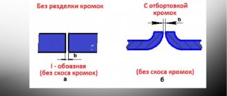
3. Pipeline joints are welded along the fins on both sides to eliminate areas of the seam that were not welded by the manufacturer. One-sided welding can only be done if the fins have previously been chamfered by 30°. The root seam must be welded to its full depth.
4. A small gap is allowed between the fins. It can be used for any type of welding. The gap size is 1.5–3 mm. If there is no gap, then it is necessary to cut the fins to the required width mechanically.
5. When a gap of 3 to 5 mm is obtained or the fins are displaced, welding is carried out in reverse steps from different ends.
6. The areas of the seam that were not welded in production are processed immediately by two master welders, moving from the center of the seam to its periphery.
7. Welding of joints occurs using the reverse step method. Having finished welding the seams on one side of the part, the master moves to the other side and does everything in the same order.
8. Flux-cored wire works only with direct current with reverse polarity.
Standard SWD plasma units, technical specifications:
| Type SWD | SWD 500 | SWD 1000 | SWD 1250 | SWD 1500 | SWD 2000 | SWD 2500 | SWD 3000 | |
| Maximum workpiece length up to* | mm | 600 | 1100 | 1350 | 1600 | 2100 | 2600 | 3100 |
| Workpiece thickness* * | mm | 0.5 – 5 (maximum up to 10 mm)* | 1,0 – 5(10) | |||||
| Min. diameter* | mm | 50 | 80 | 80 | 120 | 190 | 200 | 250 |
| Max. diameter* | mm | 800 | 800 | 800 | 800 | 800 | 800 | 800 |
| Option : increase max. diameter up to 1500, 2000, 2500 mm | ||||||||
| Torch speed | m/min | 0,1 — 7 | ||||||
| Welding speed*** | m/min | up to 4 | ||||||
| The diameter of the wire | mm | 0,6 — 2,4 | ||||||
| Welding gas, pressure | — | Argon, 2.5 atm | ||||||
| Gas consumption | l/min | 0,1 — 20 | ||||||
| Voltage | IN | 3 x 400±10% | ||||||
| Frequency | Hz | 50 / 60 | ||||||
| Power consumption | kW | 15 - 20 kW (depending on the built-in source) | ||||||
| Pressure in the pneumatic network | atm | 2,5 | ||||||
| Protection class | IP 23 | |||||||
| Dimensions***: | ||||||||
| -length | mm | 2058 | 2528 | 2778 | 3028 | 3528 | 4028 | 4528 |
| -width | mm | 800 | 750 | 750 | 750 | 750 | 750 | 1400 |
| -height | mm | 2300 | 2300 | 2300 | 2300 | 2300 | 2300 | 2300 |
| Weight**** | kg | 1300 | 1600 | 1750 | 1900 | 2200 | 2500 | 2800 |
ATTENTION! *Possibility of changing the specified parameters according to the customer’s technical specifications, reducing the minimum diameter or increasing the maximum **It is possible to reduce the minimum welding thickness to 0.1 mm and increase the maximum welding thickness to 10 - 12 mm according to the customer’s technical specifications. *** Depends on the brand and thickness of the metal, the gap between the joining edges **** Weight and dimensions may vary depending on the installation configuration and its design
| You can watch a demonstration of welding stainless steel chimneys without an additive 0.5 mm thick, as well as plasma welding of titanium and aluminum using SBI equipment in the video. |
Safety rules for pipe welding
Welding the longitudinal seam of a pipe is performed using special equipment that is unsafe for humans. Therefore, special rules have been developed, compliance with which will help preserve the life and health of a specialist:
- Complete insulation of the conductors through which electric current flows.
- Grounding the installation housing.
- Use dry clothing and gloves (mittens).
- Rubber shoes or a similar mat under your feet.
- A mask with a shield or goggles attached to it. They prevent sparks from entering and prevent the technician from being blinded.
The success of the work depends not only on theoretical knowledge, but also on the extensive practical experience of the specialist. This can be achieved by working with small workpieces, which will not later be used in critical areas.
Weldable materials:
— stainless steel — low-carbon steel — galvanized steel: plasma soldering without zinc burning — aluminum alloys (for configuration with PMI 350 AC) — copper, brass — titanium — special materials
More details can be found in the article “Plasma seam welding: features and advantages when welding various metals”
The installations are divided into standard ones with a length of up to 3,000 mm (SWD 3000) and non-standard, special ones, which are carried out according to the customer’s technical specifications and have a long welding length of up to 8,000 mm or are designed for welding large diameters.
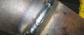
Result
Photos of the finished, smooth seam indicate that we have successfully completed the task.
Before:
After:
Of course, to obtain an ideal result, it is necessary to more precisely adjust the parameters of the welding source and carriage. But in general, we can say that the configuration coped with the task perfectly. The tractor independently monitors the seam, and the operator does not have to change anything during the process.
I would also like to draw your attention to the fact that this set of equipment will allow you to perform other tasks, for example, welding long straight (longitudinal) seams in any position .
Assembling and installing the carriage
After compiling a list of the required products, we packed everything, arrived at the enterprise and began assembly.
Installing Rail Titan on a guide rail.
Setting up and connecting the carriage.
First, unpack the carriage and guide rail. We install magnets on the rail and fix the tractor on it. Then we connect the additional modules to the carriage that we wrote about above. It is worth noting that everything is done as simply and intuitively as possible. The kit comes with a manual containing detailed pictures for assembly.
Welding carriage assembly diagram.
Finally we connect the cables. It is also impossible to make a mistake here, the cables are marked, each has its own socket. Don’t forget about connecting the control panel - you can then remove it from the carriage (it’s on a magnet) and control the process remotely .