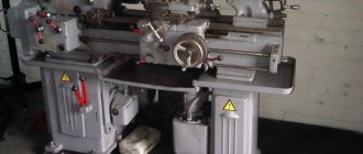
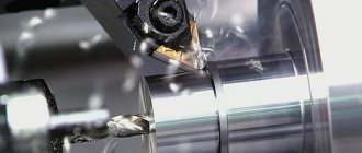
Screw-cutting lathe 1M63N (3000) is metalworking equipment for industrial use, which is used to perform wide-profile turning operations (including turning conical workpieces and cutting all types of threads).
Design features
The design and technical performance of the screw-cutting lathe 1M63N (3000) are characterized by the following features:
- rigid frame with increased vibration resistance and protection from temperature fluctuations;
- controlled spindle head rotation speed and feed speed adjustable over a wide range;
- double-prism bed guides, ensuring long-term operation of the screw-cutting lathe 1M63N (3000) without loss of accuracy;
- the possibility of reverse rotation of the spindle for thread cutting (speed is 30% higher than with direct rotation);
- turning of long-length conical workpieces is carried out with simultaneous longitudinal movement of the support and rotary feed of the cutting slide;
- feed box with a rigid kinematic chain and two electromagnetic clutches for switching feeds without stopping work;
- all critical gears of the kinematic chain of the screw-cutting lathe 1M63N (3000) are made of ground and hardened alloy steel;
- the working area has protective fences, and the safety of the main technological processes is ensured by blockers.
Equipment
The basic equipment of the screw-cutting lathe 1M63N (3000) includes:
- three-jaw chuck;
- movable steady rest (20-150 mm);
- fixed steady rest (20-350 mm).
When purchasing a screw-cutting lathe 1M63N (3000), you can additionally order:
- four-jaw chuck with a diameter of 500 mm;
- fixed rests of various sizes (200-410 mm, 40-215 mm, 20-160 mm);
- cone ruler;
- thread indicator;
- quick release tool holder.
The spindle of the 1m63 machine is mounted on two bearings:
- The front spindle bearing is a special 2-row radial bearing with short cylindrical rollers and a tapered inner ring, with adjustable radial clearance.
- The rear spindle bearing is an angular contact ball, working in tandem with a thrust ball bearing that absorbs axial feed forces during straight turning.
A rod with a diameter of up to 65 mm passes through the 70 mm spindle hole.
The spindle receives from the gearbox 22 stages (actually 24 stages, 2 of which overlap) of rotation in the range from 10 to 1250 rpm (progression denominator 1.26) and 11 reverse rotation speeds in the range from 18 to 1800 rpm.
The spindle speed is changed by moving the gear blocks along the splined shafts using two handles located on the front wall of the headstock. The spindle is reversed by a friction clutch. Braking - electromagnetic clutch.
The front end of the spindle is made according to GOST 12593 (DIN 55027, ISO 702-3-75) for a rotary washer, with a centering short cone 1:4 (7°7′30″). The nominal diameter of the cone is D = 139.719 mm, the nominal size of the spindle end is 8. The internal (tool) cone of the spindle is Morse 6. The standard diameter of the lathe chuck is 250, 315, 400, 500 mm, version - type 2 (see article Lathe chucks)..
The support of the 1m63 machine of a cross design has a mechanical movement of the upper part, which allows turning long cones. Turning of short tapers is also carried out by moving the upper part of the support.
The caliper carriage moves along the frame guides (longitudinal movement), and the transverse caliper slide moves along the carriage guides (transverse movement); both can be manual, mechanical, working and accelerated. The rotating part of the caliper, located on the transverse slide, has guides for moving the upper part of the caliper (cutting slide) with the cutting head. The lower part of the support (cutting slide) can also be moved manually and mechanically. The cross screw nut has a slot for adjustment to eliminate backlash. The axial forces of the transverse screw and the screw of the upper slide are absorbed by thrust ball bearings. The guides for the longitudinal movement of the caliper have textolite linings.
All basic operations are mechanized in the machine:
- longitudinal mechanical movement of the caliper (longitudinal working feeds)
- transverse mechanical movement of the caliper (transverse working feeds)
- mechanical movement of the cutting slide (working feed of the cutting slide)
- accelerated movements of the caliper in the longitudinal direction from an individual electric motor
- accelerated movements of the caliper in the transverse direction
- accelerated movements of the cutting slide
- The spindle is also braked automatically when the friction clutch is turned off.
Changing the feed rates and adjusting the pitch of the thread being cut is carried out by switching the gears of the feed box and adjusting the set of interchangeable gears.
Mechanical movement of the upper part of the support allows turning of long cones. Turning of short tapers is also carried out by moving the upper part of the support.
Changing the feed rates and adjusting the pitch of the thread being cut is carried out by switching the gears of the feed box and adjusting the set of interchangeable gears.
The support has rapid movement in the longitudinal and transverse directions, which is carried out by an individual electric motor.
Closed apron with removable front wall (lid). The movement of the caliper group is transmitted by an apron from the lead screw or lead shaft. Due to the presence of 4 electromagnetic couplings in the apron, control of the apron is concentrated in one handle, and the directions of turning the handle on coincide with the direction of feed movement. An additional press of the button built into the same handle activates the accelerated movement of the caliper. Thanks to: the presence of an overrunning clutch in the apron, the inclusion of rapid speed is possible when the feed is on. To avoid simultaneous activation of the motherboard, the nuts and the feed of the activation handle are interlocked.
Closed feed box. Corrected gears installed in the feed box make it possible to cut two types of threads, metric and inch, without rearranging replaceable gears. When rearranging replaceable gears, it is possible to cut two more types: modular and pitch threads. Direct connection to the screw is also provided (bypassing the feedbox mechanisms) for cutting precise and special threads. To obtain increased feed or right-hand threads, a gear block located in the gearbox is provided. The feed box housing has 2 longitudinal bores in which shafts are mounted on rolling bearings. Gears are made of chrome steel and hardened. The selection of feed rates is carried out using two handles by moving the gear blocks. Selecting the type of thread or switching on the feed is also done using handles. To turn on the screw directly, handle 5 must be placed in the “metric thread” position, handle 1 in the “screw directly” position, handle 8 in the “lead screw” position (see control diagram Fig. 6; 7).
The 1M63N machine is time-tested.
This screw-cutting lathe of normal accuracy 1m63N is designed to perform various turning operations, such as turning cylindrical surfaces, trimming ends, turning grooves, cutting off a machined part, boring internal cylindrical surfaces, drilling, countersinking, reaming, processing conical surfaces, as well as for cutting metric, inch and pitch threads. High drive power and rigidity of the machine, a wide range of spindle speeds and feeds allow full use of the capabilities of progressive tools when processing various materials.
Technical characteristics 1M63N Largest diameter of the workpiece, mm:
set over the bed 700, which is processed above the bed 630, which is processed above the caliper 350 of the 900* set of 900*
The highest length of the workpiece, mm 1500,2000,3000,4000,8000,8000,100,000 , the length of the recess in the bed from the end of the spindle flange, mm 450* end of the headstock spindle according to DIN 11M Number of spindle speed stages 22 Diameter of the cylindrical hole in the spindle, mm 105 Spindle speed limits, rpm 10…1250 Caliper
working feed limits, mm/rev:
longitudinal 0.033...5.6 transverse 0.013...2.064 cutter slide 0.010...1.76
Limits of pitches of cut threads:
metric, mm 1…224 inch, number of threads per 1″ 28-0.25 modular, module 0.25-56 pitch, pitch 112…0.5
Accelerated movement of the caliper, mm/min:
longitudinal 5.2 transverse 2
Maximum weight of the workpiece being installed, kg 3500 Main movement drive power, kW 15
Overall dimensions of the machine 1М63Н, mm:
length 3750,4200,5250,6230,7250,10300,12470
width 1780 height 1550
Weight of screw-cutting lathe 1M63N, kg 4840,5100,5750,6530,9000,11800,13200 * For machines with GAP.
Design Features
- The rigidity, vibration resistance and temperature stability of the technological system make it possible to obtain the necessary processing accuracy.
- The two-prism guides of the frame, combined with the high reliability of other components, ensure a long service life of the machine while maintaining the original accuracy.
- The frequency of reverse spindle rotation is 1.3 times higher than direct spindle rotation, which reduces thread processing time.
- Turning of long cones is carried out by simultaneous longitudinal feed of the support and feed of the cutting slide with their corresponding rotation.
- Turning of short cones is carried out by mechanical feeding of a cutting slide, turned to the desired angle.
- The feed box has a high rigidity kinematic chain; all power gears of the kinematic chain are made of alloy steel, hardened and ground.
- Guards for the cutting area and chuck, electrical and mechanical interlocks guarantee safe operation of the machine.
Design and operation of the main components of the machine
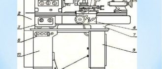
The machine consists of the following main components: Bed 1, feed box 2, replacement wheels 3, headstock 4 with spindle 6, electrical cabinet 5, apron 7 and support 9, movable 8 and fixed 10 rests, tailstock 11, electric motor for rapid movement support 13, support mechanism for the lead screw and shaft 14. Bed.
The bed is the basic assembly unit on which other assembly units are mounted. The bed is solid cast with stands, has two prismatic guides for the carriage and two for the tailstock, one of which is flat. Inside the frame there are inclined hatches (windows) for removing chips and coolant. The right cabinet contains a tank with emulsion and an electric pump. The main drive electric motor is mounted on the left pedestal at the back. Headstock. The headstock is installed on the left head part of the bed. All gears of the kinematic chain are mounted on shafts and spindles, made of chromium steel, hardened and ground. The shafts are mounted on rolling bearings. The spindle with a through hole and internal cones has two supports. The front support is a double-row bearing with short cylindrical rollers. The rear support is an angular contact bearing paired with a thrust ball bearing. Changing the spindle rotation speed is achieved by moving gear blocks along splined shafts using two handles located on the front wall. Direct and reverse rotation of the spindle is carried out by a friction mechanical clutch, and braking is carried out by an electromagnetic clutch. Tailstock. The tailstock moves along the bed guides on four radial ball bearings installed in the bridge. The headstock is secured to the frame guides using two strips with four bolts. The transverse displacement of the headstock body relative to the bridge is carried out using two screws and a nut installed in the bridge. The quill is moved by a handwheel. Caliper. The support of the cross design has longitudinal movement along the prismatic guides of the frame and transverse movement along the carriage guides. Movement can be carried out manually or mechanically. There is a mechanism for quickly moving the caliper. The rotating part of the caliper has guides for moving the upper part of the caliper with the cutting head. Apron. Closed apron with a removable front wall (lid). The movement of the caliper is transmitted through the apron from the lead screw or lead shaft. The apron mechanism is equipped with four electromagnetic clutches, which made it possible to concentrate control on one handle, and the directions of activation of the handle coincide with the direction of feed movement. The same handle has a built-in caliper fast travel button. Thanks to the presence of an overrunning clutch in the apron, high speed can be activated when the feed is on. Feed box . The feed box has two longitudinal bores in which shafts are mounted on rolling bearings. The gears are made of chrome steel and hardened. Adjustable gears make it possible to cut two types of threads, metric and inch, without rearranging replacement gears. When rearranging replaceable gears, it is possible to cut two more types of threads - modular and pitch. Replaceable gears . Replaceable gears located on the wall of the headstock housing allow for feeding and cutting metric, inch, modular and pitch threads in accordance with the passport data. Lunettes . For processing non-rigid parts with a diameter of 20 to 150 mm, the machine is equipped with movable and fixed rests. The steady rests are equipped with replaceable rollers and crackers, installed depending on the operating conditions. Cooling. From the electric pump installed in the right cabinet of the frame, the coolant is supplied to the tool through a pipeline and hose, and then flows into two troughs installed in front and behind the machine, from where it returns to the electric pump tank.
The troughs and tank must be cleaned at least once a month. You can get more detailed information here https://www.td-osz.ru/ beconected.com
Design
The basis of the 1M63N screw-cutting lathe is a cast iron bed with two or three pedestals for installation on the supporting surface (depending on the length of the machine). Two prismatic working guides located on the frame serve to move the caliper carriage, as well as adjust the position of the tailstock.
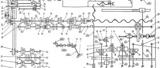
Kinematic diagram of a 1M63N screw-cutting lathe
Inside the frame body, under the working area, there are hatches for removing chips and draining coolant. The coolant and lubricant is reused many times, thanks to its return to the container through a filter system.
The outer (front and rear) cabinets of the frame are hollow. The main drive motor is located in the front (left), and the pump electric motor and a tank with cooling emulsion are located in the rear (right).
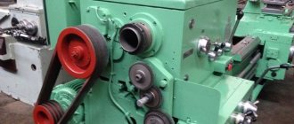
On the rear wall of the headstock there is a block of replaceable gears (guitar) for transmitting and adjusting rotation from the headstock to the feed shaft. Sets of replaceable gears allow you to rebuild the machine to cut threads of acceptable types.
Guitar screw-cutting lathe 1М63Н
Lubrication of the gears of the 1M63N screw-cutting lathe and its support bearings is carried out automatically using a mechanical oil pump driven from the main shaft of the headstock.
The high-quality alloy steel used for the manufacture of gears, heat-treated after the parts are manufactured, allows maintaining the accuracy of workpiece processing throughout the entire service life of the machine.
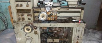
Feed box for screw-cutting lathe 1M63N
Gearbox of screw-cutting lathe 1М63Н
1m63n technical specifications | Screw-cutting lathe
| Characteristic name | Unit measurements | Meaning |
Processed workpieces | ||
| The largest diameter of the installed workpiece | ||
| above the bed | mm | 700 |
| above the caliper | mm | 350 |
| above the recess in the bed | mm | 900* |
| The largest diameter of the workpiece being processed | ||
| above the bed | mm | 630 |
| above the caliper | mm | 350 |
| Maximum length of workpiece processed | mm | 750; 1500; 2000; 3000; 4000; 5000; 8000; 10000 |
| Length of the recess in the frame from the end of the spindle flange | mm | 450* |
| The largest weight of the installed workpiece | kg | 3500 |
| Height of the cutter installed in the tool holder | mm | 32 |
Spindle | ||
| Headstock spindle end size according to DIN | 11M | |
| Internal cone in the spindle headstock (metric) | 115 | |
| Number of spindle speed steps | 22 | |
| Diameter of cylindrical hole in spindle | mm | 105 |
| Spindle speed limits | rpm | 10—1250 |
| Working Feed Limits | ||
| longitudinal | mm/rev | 0,033—5,6 |
| transverse | mm/rev | 0,013—2,064 |
| cutting sled | mm/rev | 0,010—1,76 |
Parameters of cut threads | ||
| Limits of pitches of cut threads | ||
| metric | mm | 1—224 |
| inch | threads/inch | 28—0,25 |
| modular | module | 0,25—56 |
| pitching | pitch dia | 112—0,5 |
Caliper | ||
| Accelerated movement of the caliper | ||
| longitudinal | mm/min | 5200 |
| transverse | mm/min | 2000 |
Drive unit | ||
| Maximum cutting force | kN | 20 |
| Maximum spindle torque | kNm | 3 |
| Main drive power | kW | 15 |
Dimensions and weight | ||
| Overall dimensions (including electrical equipment) | ||
| length | mm | 3000; 3740; 4230; 5240; 6240; 7240; 10300; 12420 |
| width | mm | 1780 |
| height | mm | 1550 |
| Weight | kg | 4200; 4840; 5100; 5750; 6900; 9000; 11800; 13200 |
www.stanoktehpasport.ru
Description of the lubrication system of the 1M63.01 machine
The 1M63.01 machine uses an automatic centralized lubrication system for the spindle head and feed box.
The pump, driven from the main drive electric motor through a belt drive, sucks oil from the oil bath and delivers it through a strainer to the spindle bearings and oil distribution trays. About a minute after turning on the electric motor, the oil indicator disk on the spindle head begins to rotate. Its constant rotation indicates normal operation of the lubrication system.
During operation, it is necessary to monitor the rotation of the oil indicator disk on the spindle head of the 6K20 machine. When it stops, you must immediately turn off the machine and check the filter. Remove the filter mesh elements in the plastic frame. Rinse each element in kerosene until completely clean. Do not blow out the filter elements with compressed air, as this may damage the fine mesh. After cleaning, assemble and install the filter.
ATTENTION! Filters must be cleaned before and after each oil change. In a new machine, it is advisable to clean the strainer at least twice a week during the first two weeks, and then once a month.
Every day before starting work, you need to check the oil level in the tank using the indicator and, if necessary, add it through the hole in the filler filter. When changing the oil, the reservoir is drained through a plug. Before filling the tank with oil, it must be cleaned and rinsed with kerosene.
The apron mechanism is automatically lubricated by an individual plunger pump. Oil is poured into the housing through hole 5 (Fig. 3), closed with a plug, and drained through hole 6 (Fig. 3). The oil level is controlled by the oil indicator on the front side of the apron.
The frame guides are lubricated using a centralized lubrication system of the caliper apron (repeatedly, depending on the intensity of use).
The guides of the transverse carriage, the upper carriage, as well as their lead screws must be lubricated using an oil can.
The carriage guides and cross slides are lubricated at the beginning and middle of the shift until an oil film appears on the guides.
Every day at the end of the shift, you need to remove the cutting head from the 1M63.01 lathe, clean its working surfaces and lubricate the conical axis of the tool holder.
Replacement gears and the axis of the intermediate replacement gear 12 (Fig. 3) are lubricated manually with CIATIM-203 GOST 8773-73 grease.
The support bushings of the replacement gears are lubricated using an oil can.
The remaining points are lubricated manually using the oil can supplied with the machine.
ATTENTION! The first oil change should be made a month after putting the 1M63.01 machine into operation, the second - after three months, and then strictly following the instructions of the lubrication card
Screw-cutting lathe 1M63N – YUZHSTANKOMASH
The 1M63 (1M63n) machine is designed to perform a variety of turning operations, including turning cones and cutting threads: metric, inch, modular, pitch. High drive power and rigidity of the machine, a wide range of spindle speeds and feeds allow you to fully utilize the capabilities of advanced tools when processing various materials.
Technical characteristics 1M63n
| Parameter | Meaning |
| max dia. installed part, mm | 700 |
| max dia. processing over the support, mm | 350 |
| Spindle hole diameter, mm | 82 |
| max torque on spindle, kN/m | 3,0 |
| max cutting force Pz, kN | 20 |
| max weight of the part installed on the machine in the centers, kg | 4000 |
| Machine accuracy class | H |
| Bed width, mm | 580 |
| Engine power, kW | 18,5 |
Basic equipment 1M63n
- 3-jaw self-centering. cartridge diameter 400 mm;
- 4-position tool holder;
- Set of replacement gears.
- Center distance 3000 mm;
- Center distance 5000 mm;
- Center distance 8000 mm.
Optional extensions or versions 1M63N
- fixed steady diam. 20-350 mm;
- fixed steady diam. 210-390 mm;
- fixed steady diam. 40-215 mm;
- movable steady diam. 30-200 mm;
- movable steady diam. 20-150 mm;
- installation of GAP;
- cone ruler;
- thread indicator;
- digital display device on 1 or 2 axis;
- chuck 4-jaw dia. 400 mm with independent movement of the cams;
- chuck 4-jaw dia. 670 mm with independent cam movement;
- chuck 4-jaw dia. 800 mm with independent movement of the cams;
- center rotating into the tailstock quill;
- wedge supports;
- spindle hole diameter 105 mm;
- variable frequency drive of the main movement;
- machine accuracy class P;
- max weight of the part installed on the machine at the centers is 6000 kg;
- max weight of the part installed on the machine in steady rests is 8000 kg;
- center distance 2000 mm;
- center distance 4000 mm;
- center distance 10000 mm.
Screw-cutting lathes Vistan (Belarus), Gas and Oil, Russia), Chemical.
permalink. pvusm.com
Controls
Most of the controls of the 1M63N screw-cutting lathe are concentrated on the headstock, carriage and caliper apron. The movement of the caliper in working directions can be carried out either mechanically or manually. Installed overrunning clutches allow you to enable fast feed of the caliper without stopping the machine. There is an electrical lock to prevent rapid feed when the lead screw nut is engaged.
Support for screw-cutting lathe 1М63Н
MACHINE TOOLS ©™
| The largest diameter of the installed workpiece, mm | |
| - above the bed | 700 |
| - above the caliper | 350 |
| - above the recess in the bed | 900* |
| The largest diameter of the workpiece being processed, mm | |
| - above the bed | 630 |
| - above the caliper | 350 |
| Maximum length of workpiece processed, mm | 750; 1500; 2000; 3000; 4000; 5000; 8000; 10000 |
| Length of the recess in the frame from the end of the spindle flange, mm | 450* |
| Maximum weight of the installed workpiece, kg | 3500 |
| Height of the cutter installed in the tool holder, mm | 32 |
| Headstock spindle end size according to DIN | 11M |
| Internal cone in the spindle headstock (metric) | 115 |
| Number of spindle speed steps | 22 |
| Diameter of cylindrical hole in spindle, mm | 105 |
| Spindle speed limits, rpm | 10—1250 |
| Limits of working feeds, mm/rev | |
| - longitudinal | 0,033—5,6 |
| - transverse | 0,013—2,064 |
| - cutting slides | 0,010—1,76 |
| Limits of pitches of cut threads | |
| — metric, mm | 1— 224 |
| — inch, threads/inch | 28—0,25 |
| - modular, module | 0,25—56 |
| — pitch, pitch dia. | 112—0,5 |
| Accelerated movement of the caliper, mm/min | |
| - longitudinal | 5200 |
| - transverse | 2000 |
| Maximum cutting force, kN | 20 |
| Maximum torque on the spindle, kNm | 3 |
| Main drive power, kW | 15 |
| Overall dimensions (including electrical equipment), mm | |
| - length | 3000; 3740; 4230; 5240; 6240; 7240; 10300; 12420 |
| - width | 1780 |
| - height | 1550 |
| Weight, kg | 4200; 4840; 5100; 5750; 6900; 9000; 11800; 13200 |
www.stanok-machinetools.com
Screw-cutting lathe 1M63N (1M63)
| Characteristic | 1M63N (1M63) |
| Largest workpiece diameter: | |
| installed above the bed, mm | 700 |
| processed above the bed, mm | 630 |
| processed above the support, mm | 350 |
| Maximum length of workpiece processed, mm | 750, 1500, 2000, 3000, 4000, 5000, 8000, 10000 |
| Maximum length of the part installed in the recess of the frame, mm | 900 |
| Recess length from the end of the spindle flange, mm | 450 |
| Diameter of cylindrical hole in spindle, mm | 105 |
| DIN flanged spindle end | 11M |
| Number of spindle speed steps | 22 |
| Spindle speed limits, rpm | 10 — 1250 |
| Feed size: | |
| longitudinal, mm/rev | 0,06 — 1,4 |
| transverse, mm/rev | 0,024 — 0,518 |
| cutting slide, mm/rev | 0,019 — 0,434 |
| Size of thread cutting steps: | |
| metric, mm | 1 — 224 |
| inch, threads/inch | 28 — 0,25 |
| modular, module | 0,25 — 56 |
| pitch, pitch dia. | 112 — 0,5 |
| Accelerated movement of the caliper, m/min: | |
| longitudinal | 5,2 |
| transverse | 2 |
| Main drive power, kW | 15 |
| Maximum weight of the workpiece in centers, kg | 3500 |
| Weight 1М63Н (1М63), kg | 4200, 4840, 5100, 5750, 6530, 9000, 11800, 13200 |
| Dimensions: | |
| length, mm | 2950, 3750, 4200, 5250, 6230, 7250, 10300, 12470 |
| width, mm | 1780 |
| height, mm | 1550 |
www.russtanko.ru
Screw-cutting lathe 1М63Н-1
| Characteristic | 1M63N-1 |
| Largest workpiece diameter: | |
| installed above the bed, mm | 700 |
| processed above the bed, mm | 630 |
| processed above the support, mm | 350 |
| Maximum length of workpiece processed, mm | 1500 |
| Maximum length of the part installed in the recess of the frame, mm | 900 |
| Recess length from the end of the spindle flange, mm | 450 |
| Diameter of cylindrical hole in spindle, mm | 105 |
| DIN flanged spindle end | 11M |
| Number of spindle speed steps | 22 |
| Spindle speed limits, rpm | 10 — 1250 |
| Feed size: | |
| longitudinal, mm/rev | 0,06 — 1,4 |
| transverse, mm/rev | 0,024 — 0,518 |
| cutting slide, mm/rev | 0,019 — 0,434 |
| Size of thread cutting steps: | |
| metric, mm | 1 — 224 |
| inch, threads/inch | 28 — 0,25 |
| modular, module | 0,25 — 56 |
| pitch, pitch dia. | 112 — 0,5 |
| Accelerated movement of the caliper, m/min: | |
| longitudinal | 5,2 |
| transverse | 2 |
| Main drive power, kW | 15 |
| Maximum weight of the workpiece in centers, kg | 3500 |
| Weight 1М63Н-1, kg | 4840 |
| Dimensions: | |
| length, mm | 3750 |
| width, mm | 1780 |
| height, mm | 1550 |
www.russtanko.ru
Description of work
Before starting work with equipment such as a lathe, it is imperative to study the operating instructions, as well as familiarize yourself with the safety rules.
Neglecting them can harm your health. If you do not have a lathe education or special training, then it is in your best interests not to operate the machine without the strict supervision of a specialist.
After assembling and connecting the unit, you also need to clean it and prepare it for use. Having tools and parts scattered around the workplace is unacceptable. The drive is turned on by the start button, which can be found near the feed box. There is another start button, which is located on the dashboard of the carriage. When starting the engine, the clutch must be turned off!
To set the caliper (carriage) in motion, you need to connect the friction clutches located in the apron. Four clutches, one half of which provide longitudinal movement, the other half transverse, are controlled by a switch located on the apron. The switch has 1 vertical (neutral) position and 4 inclined positions, according to the direction of movement of the caliper. The switch head has a button that turns on the high-speed movement of the caliper.
In the event of a serious breakdown, the machine should be sent for repair. Before doing this, be sure to clean the unit from dirt and chips and drain the liquids. Together with the machine, a technical passport, a technical inspection certificate and a list of assembled spare parts, which are sent dismantled from the machine, must be sent. If any spare parts are missing, the repair plant will produce them for a fee.