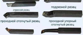
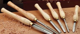
Cutters are used for processing metal or wooden products, metal ceramics. They are mounted on technical machines that can perform a variety of jobs (turning, planing, slotting). Cutters are usually made from high-strength varieties of steel, which may contain alloying additives that increase strength and minimize the risk of rust. A popular type of such tool is the groove cutter. It has a number of design differences, and is mainly used for processing conical or cylindrical products made of metal.
The tool allows you to create small but precise grooves, which is required in some part machining scenarios. But what does a groove cutter look like? How can a worker choose the right tool for his machine? What does GOST say about groove cutters? This article will discuss these issues in detail.
Brief information
A groove cutter (CR) is a tool for creating grooves on internal and external cylindrical surfaces. To use it, it must be secured in the working area of the machines. It has a simple design, and the width of the cutting part is usually 5-6 millimeters (although wider tools are available). High-strength varieties of steel are used for manufacturing (with or without alloying additives). In addition, there are metal-ceramic, mineral-ceramic cutters, and diamond-coated parts.
The KR is a universal tool - it can be used for processing metals, wood, metal ceramics, some types of plastic or stone. The production of cutters is regulated by GOST rules, and on the market you can find spare parts from European, Chinese, and Russian manufacturers. Preference should be given to European products, but you can buy Chinese or Russian KR. Advantages of using groove cutters:
- Easy to create grooves. You can create grooves with a variety of tools, but with the help of the RK they are easy to make. By selecting various tools, you can adjust the technical parameters of the grooves (depth, width, stripping quality, etc.).
- Minimum defects and damage. If the tool is used correctly, the processing is high-quality and accurate. The risk of scoring, cracks, and scratches is minimal. During operation, it is recommended to remove debris and metal dust from the core to improve the quality of processing.
- Low price, ease of use. Not only factories, but also ordinary people can afford groove cutters. To install and configure the cutter, you will need basic turning skills, so anyone with basic knowledge can handle this task.
Parting and Grooving Tool Models in SolidWorks
As mentioned in earlier articles, 3D models of a cutting tool can, of course, be built from scratch in SolidWorks. But I think there is no point in this since the tool manufacturers have already done this for us.
We go to the website, and for example, download two models of cutters under the designations: “RAG123H10-32B” , “RF123H13-2525BM” .
Sandvik coromant website
And in the search line, enter these designations one by one and download the cutters by clicking on “Download” in the “download detailed 3D model” line.
Downloading a 3D model of the tool from the Sandvik coromant website
Next, open the downloaded files and get 3D models of these cutters in SolidWorks.
Internal grooving cutter RAG123H10-32B
Parting and grooving cutter RF123H13-2525BM
As you can see, this is much easier and faster than creating a cutter in SolidWorks from scratch.
If anyone needs this model, you can download it at the end of the article!
Tool design and geometry
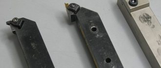
A classic groove cutter consists of two tool parts - a working head-cutter and a fixing rod, with which the spare part is secured in the machine holder. The holder rod is made of high-alloy steel, which provides high strength and protection of the tool, and also minimizes the risk of corrosion and deformation. The cutting part of the KR is made in the form of a rectangular or oval plate, which is also made of high-alloy steel.
The plate is usually made of metal that contains additives based on cobalt, manganese or tungsten - this provides the tool with high strength, so it dulls slowly. On some CDs, the head is made in the form of a replaceable head, which is also made of steel with a high content of cobalt, manganese, tungsten and similar alloying additives. Tool sharpening should be done on a sharpening machine, and it is recommended to entrust this work to an experienced worker.
A few words about the correct sharpening of groove cutters:
- During sharpening and assembly of the part, it is necessary to obtain a rake angle ranging from 15 to 25 degrees. The location of the cutter affects how the workpiece will be processed in the future while the cutting machine is running.
- The working edge should be sharpened evenly along its entire length. If you ignore this rule, then strong vibration will occur during operation of the machine, which will make cutting inaccurate. Due to vibration, the tool also heats up additionally, which will reduce the strength of the tool and make sharpening more difficult.
- Select the optimal geometry experimentally. GOST standards do not provide precise instructions regarding the sharpening of this tool due to the fact that surface treatment has specific features. Therefore, it is not possible to select a universal angle of inclination and quality of sharpening.
To optimize sharpening, it is recommended to perform it in several stages. First, you need to make several test grooves to determine the optimal sharpening parameters. Once the worker has mastered his hand, he can begin the main sharpening. Only experienced turners with experience who are fluent in their craft and know all the intricacies of working with groove cutters can skip the test groove.
Selection rules
The first thing you should focus on when choosing a groove turning tool is a drawing of the finished product, which indicates both the dimensions and shape of the grooves, as well as the tolerances for the accuracy of their geometric parameters. Naturally, the choice of cutter and its geometric parameters is influenced by the material from which the workpiece is made.
External groove cutter
When forming grooves on small parts, it is especially important to maintain a low cutting force, which minimizes the distortion that occurs during processing. Compliance with this requirement is ensured by the sharp sharpening of the groove tool, which, however, can lead to its breakage if the carbide plate material and cutting conditions are selected incorrectly - the rotation speed of the workpiece and the feed rate.
When choosing a groove cutter, you should also take into account the shape of its cutting edge, which can be straight and sharpened with a small radius. Naturally, you should not choose a product with a curved sharpening of the cutting edge if the bottom of the groove, according to the provided drawing, should be straight.
Internal groove cutter
Technical features
Most groove cutters are 20-30 centimeters long. Small parts, the length of which does not exceed 5 centimeters, are in small but stable demand (they are used in machines that are used for the manufacture of high-precision electronics). The head has the shape of a rectangular parallelogram, the height and thickness of which are 3-4 centimeters, and the width is 0.5-1 centimeter. Cutter plates are made from different materials—we list the most popular ones:
- Brazed carbide steel. A popular type of cutter, it has good technical characteristics and is cheap. The main disadvantage is that it becomes dull quickly, so you will have to sharpen it often.
- Metal ceramics with the addition of cobalt, titanium, tungsten. They are distinguished by increased strength and dull very slowly. Such cutters are suitable for processing durable products (for example, for creating recesses in steels with the addition of alloying components that increase strength).
- Mineral ceramic cutting plates. Used for high-temperature processing of very durable spare parts. Difficult to produce, therefore expensive. They quickly become unusable and are difficult to sharpen. Not recommended for processing conventional materials (too expensive).
- Cutter plates with diamond coating or diamond inserts. They easily cut materials of any strength, but can burn or burn out when the temperature rises. In addition, they are difficult to produce and therefore have a high cost.
- Composite plates based on boron nitride. A compromise option between diamond and mineral ceramic cutters. They hold temperature well and process high-strength materials well. They are not too difficult to produce, so they have a low price.
When choosing a turning tool, look at the physical properties of the part. Price is an important parameter, but when working with complex materials, it is much easier and safer to spend the extra money to get a working machine. For example, carbide brazed inserts will be useless for processing high-strength materials, so there is no point in buying them.
Damn.2
Damn.2
table 2
Dimensions, mm
| Cutter section | Largest cut diameter | ||
| 6x6 | 1,5 | 10 | |
| 8x8 | 5 | 2,0 | 12 |
| 10x10 | |||
| 12x12 | 8 | 16 | |
| 16x10 | 3,0 | 30 | |
| 20x12 | 12 | ||
| 4,0 | 35 | ||
| 25x16 | 14 | 3,0 | 30 |
| 5,0 | 50 | ||
| 32x20 | 18 | 4,0 | 35 |
| 6,0 | 60 | ||
| 20x12 | 12 | 4,0 | 35 |
| 25x16 | 14 | 5,0 | 50 |
| 32x20 | 18 | 4,0 | 35 |
| 6,0 | 60 |
The text of the document is verified according to: official publication Reztsy. Design and dimensions. Part 1: Sat. GOST. - M.: IPK Publishing House of Standards, 2003
Groove cutter - requirements according to GOST
The technical characteristics of the CD are specified by GOST standards, which were adopted back in the USSR. The main standard is the document GOST 2209-82, as well as its revision from 1990. A number of other regulatory documents are also in force - GOST 18874-73, GOST 18885-73, SNiP standards and others. They stipulate the main parameters of groove cutters - geometry, wear resistance, strength, marking, cutting quality, testing methods. When choosing a CD, you need to remember the following:
- Most of the cutters on the market are of Russian, Chinese or European origin. Russian products have good technical characteristics, a long shelf life, and do not require additional requirements for transportation or storage. Another plus is the reasonable price. However, they are recommended for processing ordinary parts at low temperatures.
- If you want to process a durable and/or heated surface, then preference should be given to spare parts from European manufacturers. They cost more, but their technical parameters are better. In addition, they dull more slowly, are easily stored, and withstand exposure to water and chemicals longer.
- With Chinese parts the situation is much more complicated. Many Chinese manufacturers make quite high-quality spare parts that are not inferior to Russian and even European analogues. And they are very cheap. However, there are still a lot of Chinese low-quality cutters on sale, so you need to choose parts carefully. It makes sense to purchase Chinese products in small quantities (in case of bad incisors, you will not lose much money).
Incisor directions
Depending on the direction in which the tool begins to move, cutters are divided into two types:
- Left type. The start of processing starts from left to right. You can determine this type by placing your left hand on the product. The bent thumb will be located on the side of the cutting edge of the incisor.
- Right type. The serve is performed from right to left. To determine this type of cutter, you should place your right hand on it. Your thumb will be on the cutting edge side of the tool.
Rules for selection and application
There are many types of groove cutters on sale, which may differ in many parameters - design, material, technical properties. When choosing, buy spare parts based on alloy steel, which is reliable, durable, and does not require frequent sharpening. To ensure that the CD lasts for a long time without sharpening, follow these tips:
- Consider the characteristics of the material before processing (materials science will help with this). For example, for processing stainless steel, you should not buy a tool based on carbon tool steel - the tool will quickly become dull, so you will have to sharpen it often.
- Study the operation of the machine before purchasing the tool. Wear, number of revolutions, machine functionality and other parameters should be taken into account. If the machine is in disrepair, then first repair it - and only then proceed to install the control system on it.
- Consider the temperature conditions at which the workpieces are processed. As the temperature rises, the material expands, so the quality of processing and cutting properties of the tool will decrease. Some cutters are coated with diamond; when heated, it burns out quickly.
- Monolithic and composite cutters are available for sale. The former are very cheap, but sharpening them is difficult and impractical. Composite cutters are more expensive, but they are much easier to use, and sharpening them is much easier (a novice turner can handle it).
- When processing, also take into account the nature and physical properties of the workpiece. Key parameters that are worth paying attention to are surface uniformity, the presence of depressions, small flaws, groove depth, cleanliness and precision of processing.
Damn.1
Damn.1
Table 1
Dimensions, mm
| Cutter section | |
| 4x4 | 4 |
| 6x6 | |
| 8x8 | 6 |
| 10x10 | 8 |
| 12x12 | 10 |
| 16x16 | 12 |
2. Structural elements and geometric parameters of cutting tools are indicated in Figure 2 and Table 2.
Content
1 Scope……………………………………………1
2 Normative references……………………………………………………..1
3 Technical requirements……………………………………………………3
4 Completeness…………………………………………………………….5
5 Acceptance rules………………………………………………………..5
6 Control and testing methods………………………………………………………5
7 Safety requirements………………………………………………………..9
6 Transportation and storage……………………………………..9
in
GOST 26613—2016
INTERSTATE STANDARD
TURNING CUTTERS WITH MECHANICAL FASTENING OF REPLACEABLE MULTIGEDAL INSERTS
Specifications
Lethe tools with mechanically clamped changeable indexable inserts.Specifications
Date of introduction: 2018—01—01
CONTROL METHODS
4.1. Before testing, surfaces must be cleaned of grease and contamination.
4.2. The presence of gaps and their size (clauses 1.18, 1.19) are checked visually and with feeler gauges. The appearance of the incisors (clauses 1.20, 1.23, 1.24) is checked visually.
4.3. The parameters of the cutters are monitored using control means that have measurement errors of no more than:
when monitoring linear dimensions - the values specified in GOST 8.051;
when checking angular dimensions - 35% tolerance for the angle being checked;
when controlling the shape and location of surfaces - 25% tolerance on the parameter being tested.
It is allowed to use special monitoring equipment, the measurement error of which ensures the necessary accuracy.
4.4. Control of cutter sizes (clause 1.8) is carried out using reference plates, the shape and dimensions of which correspond to GOST 19043 - GOST 19045, GOST 19047, GOST 19049 - GOST 19051, GOST 19056, GOST 19057, GOST 19062, GOST 19064, GOST 19067, GOST 19069 , GOST 19070, GOST 19072, GOST 24255 or other regulatory and technical documentation.
The dimensions of the radius of curvature of the tip of the cutter must correspond to those indicated in Table 3.
Table 3
mm
| 5,556; 6,35 | 0,4 |
| 9,525; 12,7 | 0,8 |
| 15,875; 19,05 | 1,2 |
| 25,40 | 2,4 |
The maximum deviations of the linear and angular dimensions of the reference plates should not exceed:
| diameter of inscribed circle, mm | ±0,002 |
| thickness, mm | ±0,01 |
| apex radius, mm | ±0,02 |
| apex angle | ±5′ |
| size, mm | ±0,002 |
(Changed edition, Amendment No. 1.4).
4.5. Control of the roughness parameters of the surfaces of cutter parts (clause 1.7) is carried out by comparison with roughness standards or control samples, the surfaces of which have limiting values of the roughness parameters. Comparison is carried out using a magnifying glass LP1-4 according to GOST 25706.
4.6. Hardness control (clause 1.6) is carried out in accordance with GOST 9013 using TR devices in accordance with GOST 23677.
4.7. Excluded.
4.8. Perpendicularity control (clause 1.11) is carried out using a protractor in accordance with GOST 5378 and a calibration plate in accordance with GOST 10905.
4.9. Control of the flatness tolerance of the supporting surface of the holder (clause 1.14) is carried out using a pattern ruler and a set of feelers made in accordance with the regulatory and technical documentation.
(Changed edition, Amendment No. 1, 4).
4.10. Tests of cutters for average and 95% periods of durability, as well as for performance, are carried out on lathes that meet the standards of accuracy and rigidity established for them.
Tests must be carried out without cooling on the following processed materials, depending on the ISO groups of carbide used:
steel 45 or 50 GOST 1050 with hardness 150...241 HB - application group P;
cast iron grade SCh 25 or SCh 30 GOST 1412 - hardness 180...255 HB - application groups K and M.
(Changed edition, Amendment No. 1, 3, 4).
4.10.1. The tops of the cutters are installed along the line of the centers of the machine with permissible deviations, no more than:
| for turning external surfaces | 14 | ||
| for turning internal surfaces | +1.0 mm | ||
4.10.2. The projection of the cutting part of the cutters from the tool holder should not exceed:
| for turning external surfaces | 1,2-1,3 | ||
| for turning internal surfaces | 2,5 | ||
4.10.3. (Deleted, Amendment No. 1).
4.10.4. The surfaces of the test sample must be pre-treated to a roughness parameter of 12.5 µm, radial runout - 0.1 mm. On the workpieces, at the entry and exit points of the cutter, there should be a chamfer larger than the depth of cut.
4.10.5. Tests of cutters for performance and durability, depending on the grades of material of the cutting part and the shape of the plate, should be carried out in the modes indicated in Table 4, taking into account the correction factors in Tables 5, 6, 6a, 6b.
Table 4
| ISO application subgroup | Alloy grade | Flank wear, mm | Depth of cut, mm | Cutting speed, m/min ±10% | ||
| Feed, mm/rev ±10% | ||||||
| For interchangeable mold plates | ||||||
| W, S, K, D, T | S | P, H, R | ||||
| P01 | T30K4 | 0,6 | 1,0 | 220 0,2 | 250 0,23 | 260 0,25 |
| P10 | T15K6 MS111 | 0,8 | 2,0 | 180 0,28 | 200 0,3 | 220 0,4 |
| P20 | T14K8,MS121, MS137 | 0,8 | 2,0 | 145 0,32 | 155 0,35 | 165 0,45 |
| P30 | T5K10, TT10K8B, MS131, MS221 | 0,8 | 2,5 | 110 0,4 | 120 0,45 | 125 0,55 |
| P40-50 | T5K12, TT7K12, MS146 | 0,8 | 3,0 | 80 0,47 | 90 0,5 | 90 0,55 |
| K01 | BK2, VK3, VK3M, MC301 | 0,8 | 1,0 | 130 0,2 | 150 0,2 | 150 0,25 |
| K05 | BK60M,MC306 | 0,8 | 1,5 | 120 0,2 | 130 0,2 | 130 0,25 |
| K10 | BK6M, TT8K6, MC312 | 0,8 | 2,0 | 110 0,3 | 120 0,3 | 120 0,4 |
| K20 | BK6, BK4, MC318, MC321 | 0,8 | 2,0 | 100 0,3 | 100 0,3 | 110 0,4 |
| K30 | BK8 | 0,8 | 2,5 | 75 0,35 | 80 0,35 | 80 0,45 |
| M30 | BK10M, BK100M | 0,8 | 3,0 | 90 0,3 | 100 0,3 | 110 0,4 |
| P01-P10 | TH20 | 0,6 | 1,0 | 210 0,2 | 220 0,25 | 240 0,3 |
| P10-P20 | KHT16 | 0,6 | 2,0 | 190 0,2 | 210 0,25 | 230 0,3 |
| P30 | TB4 | 0,6 | 2,0 | 100 0,28 | 115 0,3 | 125 0,4 |
| P01* | B0K71, B013 | 0,4 | 1,0 | 350 0,2 | 400 0,25 | 420 0,3 |
| K01* | B0K71, B013 | 0,4 | 1,0 | 300 0,2 | 350 0,25 | 370 0,3 |
________________
* Tests of cutters with ceramic plates can be carried out both when turning steel 45 or 50, and cast iron SCh 25 or SCh 30.
Cutting modes during testing can be selected according to Table 4, respectively, for application groups P01 or K01.
Note. The cutting speed when testing alloy MC318 should be increased by 10%.
(Introduced additionally, Amendment No. 4).
When testing boring cutters, correction factors should be: for speed - 0.8, for feed - 0.7.
Table 5
Correction factors for cutting speed ( ), and feed ( ) depending on the radius at the tip of the cutting insert ( )
| Processed material | Correction factors depending on the vertex radius, mm | |||||
| 0,4 | 0,8 | 1,2 | 1,6 | 2,4 | ||
| Steel | 0,8 | 1,0 | 1,1 | |||
| 0,5 | 0,9 | 1,0 | 1,1 | 1,2 | ||
| Cast iron | 0,8 | 1,0 | ||||
| 0,75 | ||||||
Table 6
Correction factors for cutting speed
depending on the hardness of the material being processed
| Processed material | Correction factors for hardness NV | ||||||||||
| 150-160 | 161-170 | 171-180 | 181-185 | 186-195 | 196-205 | 206-215 | 216-225 | 226-235 | 236-245 | 246-255 | |
| Steel | 1,25 | 1,22 | 1,16 | 1,12 | 1,04 | 1,0 | 0,96 | 0,93 | 0,9 | 0,86 | 0,6 |
| Cast iron | — | — | — | 1,0 | 0,9 | 0,84 | 0,8 | 0,74 | 0,7 | 0,66 | — |
Table 6a
Correction factors for feed
depending on the entering angle
| Main plan angle | Feed correction factors for interchangeable mold plates | ||
| W, S, K, D, T | S | ||
| Steel | 45° | 1,3 | 1,25 |
| 60°; 63° | 1,15 | 1,0 | |
| 75° | — | 1,0 | |
| 90°; 95° | 1.0 | — | |
| Cast iron | 45°; 63° | 1,2 | 1,2 |
| 75° | — | 1,0 | |
| 90°; 95° | 1,0 | — | |
Tests of cutters equipped with plates with a wear-resistant coating are carried out in the modes according to Table 4, taking into account the correction factor for cutting speed:
1.25 - for single-layer coatings;
1.3 - for multi-layer coatings.
The criterion for dullness is flank wear of 0.5 mm.
Table 6b
Conformity of carbide grades with coating of subgroup C of application according to ISO
| ISO application subgroup | Coated carbide grade | |
| single-layer | multilayer | |
| P20 | T14K8+TiN (KIB), MS2210 T5K10GT | MS2215, VP1325 |
| P30 | T5K10+TiN (KIB), MS1460 | MS1465, VP1455, VP1255 |
| K20 | MS3210, VK6DT | MS3215,VP3115 |
| K30 | VK8GT | VP3325 |
The tests are carried out on standard representatives for groups of standard sizes of cutters, characterized by the unity of the fastening method in accordance with GOST 26476 and GOST 27686, the group of tool material and the shape of the cutting insert in accordance with GOST 19042.
Performance tests should be carried out at cutting conditions according to Table 4-6a for 3 minutes. After testing, the fastening of the plates should not be damaged, there should be no chipping on the plates and the cutters should be suitable for further work.
(Changed edition, Amendment No. 3, 4).
4.10.6, 4.10.7. (Excluded, Amendment No. 1).
4.10.8. Drain chips (straight or spiral tape longer than 150-250 mm) are not allowed. When it appears, for cutters of attachment method C, it is necessary to select a chipbreaker that provides crushing.
4.10.9. The cutting conditions for cutters equipped with cutting inserts with wear-resistant coatings correspond to the cutting conditions specified for cutters with cutting inserts made from a grade of base material.
4.10.10. (Deleted, Amendment No. 1).
4.10.11. Acceptance values for the average and 95% durability periods for a sample of 5 cutters must be no less than those given in Table 7.
Table 7*
_________________
* Tables 8, 9, 10. (Excluded, Amendment No. 4).
| Instrumental materials group | Acceptance values of durability periods, min | |
| average | 95% | |
| Plates made of tungsten hard alloys without tantalum and niobium carbides (TK and VK groups) | 17 | 9 |
| Plates made of tungsten hard alloys with tantalum and niobium carbides (MS and TTK groups) | 17 | 11 |
| Plates made of tungsten-free hard alloys (TN, KNT, TV groups) | 17 | 7 |
| Ceramic plates | 23 | 11 |
(Changed edition, Amendment No. 3, 4).
4.10.12. (Deleted, Amendment No. 4).
Markings used
The designation of groove cutters is encoded, which provides a complete definition of the geometric parameters of the tool included in the tables of regulatory documents. The main product markings mention parameters such as the alloy with the percentage of metal components in the alloy. For example, if you take a T5K10 cutter, then there will be an alloy based on the titanium-tungsten group, where titanium carbide is up to 5%, and cobalt is up to 10%.
To select cutting groove products, it is not enough to know only the composition of the alloy; you need to proceed from all the parameters specified by GOST.
Preface
The goals, basic principles and basic procedure for carrying out work on interstate standardization are established in GOST 1.0-2015 “Interstate standardization system. Basic provisions" and GOST 1.2-2015 "Interstate standardization system. Interstate standards. rules and recommendations for interstate standardization. Rules for development and adoption. updates and cancellations"
Standard information
1 DEVELOPED by Open Joint Stock Company "VNIIINSTRUMENT" (JSC "VNIIINSTRUMENT")
2 INTRODUCED by the Interstate Technical Committee for Standardization MTK 95 “Tool”
3 ADOPTED by the Interstate Council for Standardization, Metrology and Certification (protocol dated November 22, 2016 N9 93-P)
The following voted for adoption:
| Brief name of the country pa MK (ISO E1vv) 004-9? | Code of the country no MK (ISO 316v) 004-97 | Abbreviated name of the national standardization body |
| Belvrus | BY | State Standard of the Republic of Belarus |
| Georgia | G.E. | Gruzstandvrt |
| Kyrgyzstan | KG | Kyrgyzstvndvrt |
| Russia | RU | Rosstandart |
| Tajikistan | T.J. | Tajikstandard |
| Uzbekistan | uz | Uztvndvrt |
4 By Order of the Federal Agency for Technical Regulation and Metrology dated March 14, 2022 No. 133-st, the interstate standard GOST 26613-2016 was put into effect as a national standard of the Russian Federation from January 1, 2022.
5 INSTEAD GOST 26613-85
Information about changes to this standard is published in the annual (as of January 1 of the current year) information index “National Standards”, and the text of changes and amendments is published in the monthly information index “National Standards”. In case of revision (replacement) or cancellation of this standard, the corresponding notice will be published in the monthly information index “National Standards”. Relevant information, notices and texts are also posted on the public information system - on the official website of the Federal Agency for Technical Regulation and Metrology on the Internet ()
© Standardinform. 2017
In the Russian Federation, this standard cannot be reproduced in whole or in part. replicated and distributed as an official publication without permission from the Federal Agency for Technical Regulation and Metrology
GOST 26613—2016
ACCEPTANCE RULES
3.1. Acceptance rules - according to GOST 23726.
3.2. 3.3. (Excluded, Amendment No. 1, 4).
3.4. Tests to control 95% and average service life periods should be carried out on at least 5 cutters of the same standard size with one tip of the cutting insert for each group of tool materials according to Table 2a.
(Changed edition, Amendment No. 1, 3, 4).
3.5. The frequency of tests to control the 95% durability period is once a year, the average durability period is once every 3 years.
(Changed edition, Amendment No. 3, 4).