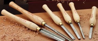
Cutters are used for processing metal or wooden products, metal ceramics. They are mounted on technical machines that can perform a variety of jobs (turning, planing, slotting). Cutters are usually made from high-strength varieties of steel, which may contain alloying additives that increase strength and minimize the risk of rust. A popular type of such tool is the groove cutter. It has a number of design differences, and is mainly used for processing conical or cylindrical products made of metal.
The tool allows you to create small but precise grooves, which is required in some part machining scenarios. But what does a groove cutter look like? How can a worker choose the right tool for his machine? What does GOST say about groove cutters? This article will discuss these issues in detail.
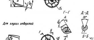
Geometric parameters and tool dimensions
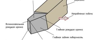
The design of any groove cutter is characterized by its geometric parameters.
- Geometry of the body or holder: L – length of the body, B and H – dimensions of the cross-sectional sides.
- Location of the cutting element in the body. The socket for the plate can occupy the entire width of the case or one of the corners. In the latter case, the width of the socket is indicated by the letter n. The plate can be placed in the socket at a certain angle to the body.
Shape of the working cutting plate: l – length of the working part of the cutter, b – height of the plate body, S – thickness.
The blade for cutting the workpiece also has its own parameters, expressed in angles.
- “Gamma” displays the front sharpening angle - this is the main element of the cutting edge.
- “Alpha” is the rear main sharpening angle.
- “Alpha” with index 1 is the rear corner for auxiliary purposes.
- "Lambda" is the angle at which the cutting edge is inclined.
- “Phi” is the main purpose angle located in plan.
- “Phi” with index 1 is an auxiliary angle located in plan.
Selection of cutters for lathes.
The selection of turning cutters for a specific metalworking operation should be approached comprehensively, assessing the shape of the part, the toughness and hardness of the metal or alloy being processed, the permissible error of deviations from the established dimensions and the required surface roughness. It should be taken into account that in addition to the material of the part, the cutting part and the cutter holder, the quality of processing will be influenced by:
- cutter feed speed and depth of cut;
- cutting edge angle and main relief angle (between the rear plane of the cutting part and the plane of the processing surface);
- chip breaking method and vibration resistance of both the holder and the cutting head;
- the shape of the socket in which the carbide plates are installed and the method of fastening the holder itself.
Markings used
The designation of groove cutters is encoded, which provides a complete definition of the geometric parameters of the tool included in the tables of regulatory documents. The main product markings mention parameters such as the alloy with the percentage of metal components in the alloy. For example, if you take a T5K10 cutter, then there will be an alloy based on the titanium-tungsten group, where titanium carbide is up to 5%, and cobalt is up to 10%.
To select cutting groove products, it is not enough to know only the composition of the alloy; you need to proceed from all the parameters specified by GOST.
Categories of cutters
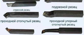
Of all the available parameters by which cutters are classified, the main one is the type of workpiece processing. Depending on their technological purpose, replacement cutters for a metal lathe are:
- Passable. Using this product, the turner processes cylindrical and conical outer surfaces of metal workpieces. Processing is carried out along the axis of rotation of the workpiece.
- Cut off. Used for cutting workpieces and trimming them.
- Shaped. Using this cutter for a metal lathe, you can grind shaped surfaces of workpieces. The tool is also used to form shaped ridges and grooves.
- Boring. The product is used for boring both through and blind holes. Boring cutters can be persistent or through.
- Slotted or grooved. Internal and external grooves in cylindrical metal workpieces are machined with these cutters. Also, this type of cutters is used in cases where it is necessary to cut the workpiece at a right angle.
- Threaded. They are used in cases where it is necessary to equip the workpiece with internal or external threads.
- Galtelnymi. Using cutters of this category, the turner can process the transition surfaces of workpieces.
- Chamfered. These cutters are used for chamfering.
This is interesting: Metal laser cutting technology - equipment, features, video
GOST standards for groove cutters
Regulatory documents have been developed for groove cutters of various modifications:
- GOST 18874-73 regulates the standards for cutting and slotting equipment, which specifies the dimensions and design of the tool, which is made of high-speed steel.
- GOST 18885-73 describes the design features of groove cutters for thread production, which are equipped with carbide plates.
- GOST 18884 - 73 - this normative act gives instructions on the size and design of cutting tools for turning, the plates of which are tipped with carbide alloys.
- GOST 28978-91 - the document defines the standard for prefabricated groove cutting tools.
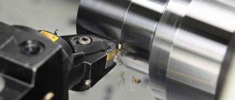
Groove cutter
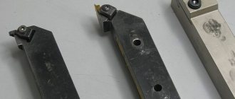
Types of groove cutters
Turning cutters for grooves come in two types, for external and internal surfaces. Accordingly, each type of work requires a tool change. Therefore, when working with several parts, first they process one surface on all of them, and then work on the other. The groove cutter for internal grooves, as well as the internal groove cutter, have a design in which the inserts can be changed.
In external machining, the use of carbide tools on inserts turns out to be practically useless, since they do not give the necessary results, and their cost is too high. When it comes to internal processing, then the issue of rigidity and the minimum diameter of the workpiece comes to the fore, since otherwise the groove cutter may simply not fit into the hole. Therefore, the internal grooving cutter must be stiffer and thinner to be versatile in use.
photo: types of groove cutters
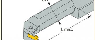
Main dimensions and materials
Turning cutters for internal grooves are available with carbide inserts:
| Height, mm | Width, mm | Working length, mm | Working part width range, mm |
| 10 | 10 | 100 | 2,5-3,5 |
| 16 | 16 | 170 | 3,5-4,5 |
| 20 | 20 | 200 | 3-6 |
| 25 | 20 | 140 | 3,5-6,5 |
| 25 | 25 | 240 | 5-6,5 |
| 32 | 32 | 200 | 5-10 |
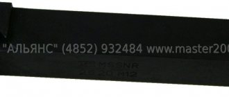
photo: dimensions of groove cutter for external grooves
The groove cutter for external grooves is produced with brazed carbide inserts:
| Height, mm | Width, mm | Working length, mm | Working part width range, mm |
| 16 | 10 | 100 | 2-10 |
| 20 | 12 | 120 | |
| 25 | 16 | 140 | |
| 25 | 20 | 140 | |
| 32 | 20 | 270 | |
| 50 | 32 | 200 |
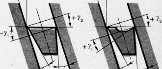
Groove cutter geometry
When selecting a cutter for a groove, a very important parameter is the rake angle, which has a strong influence on the vibration resistance of the tool. The smaller the angle, the less stability. The best option here is a value in the range from 15 to 25 degrees. The clearance angle should be between 8 and 12 degrees.
The cutting edge must be uniform, otherwise uneven grooves will be obtained. Taking into account the fact that a groove cutter is most often made of carbide materials, it is quite difficult to sharpen and here the chips are not divided into two parts, but go only in one direction. The product, unlike some other types, has only one sharpening angle.
photo: geometry of a groove cutter
Selection of Grooving Cutter
In order for a groove cutter to serve for a long time and be effective in use, its choice should be taken quite responsibly. First of all, you should pay attention to the microgeometry of the plate. Tight tolerances when machining parts can be around 0.025mm. There are several variations in the shape of the cutting insert, as a result of which the shape of the future groove depends, since it may not always be flat. Some universal type inserts have a curved cutting edge, so that the bottom is convex.
The geometry of the edge must be selected very accurately, since if the load is unevenly distributed, then wear will occur differently in all parts of the product and, as a result, it will no longer be usable. The same situation occurs when the blade begins to chip, after which it must be replaced immediately.
Cutting mode
The cutting width per pass must correspond to the required depth. The groove cutter is fed manually. This should be done within minimal limits, approximately 0.1 mm per revolution. The cutting speed is set noticeably lower, about 20% less than when working with other cutters.
There are several types of grooves, which are made using different techniques:
- Small cylindrical ones are made in one pass of the machine. The cutter is placed at a given distance, then brought into contact with the surface. Then, in one motion, a pass is made, as a result of which the product is processed.
- Grooves on the ledges and ends are made using a similar technique. Only here the depth is maintained according to the longitudinal movement dial, and the diameter is maintained according to the transverse feed dial.
- Large grooves are difficult to machine in one pass, so they are done in two steps. The first step is to draw a rectangular shape to the entire required depth. After this, the cutter is changed and the metal remaining from the sides is removed with a profile cutter.
- Rectangular wide grooves are also made in several passes. Here, both on the first pass and on all subsequent ones, you need to slowly cut through the metal not to its full depth. When the desired depth is reached, the bottom must be cleaned.
Marking of incisors
Using the T5K10 cutter as an example, we can consider the principle of marking these products. The letter “T” means that it belongs to the hard alloys of the titanium-tungsten group and there is 5% titanium carbide (the number “5” in the marking), and 10% cobalt (“K”) (the last number).
Manufacturers
- Zenitech (Switzerland);
- Proma (Czech Republic);
- Itertool (China)
Recommendations for selecting groove cutters
When choosing a groove cutter, you should be guided by the following considerations:
- First of all, they analyze the drawing according to which the part will be manufactured. The drawing shows all the parameters of the grooves: width, depth, shape, as well as standards for manufacturing accuracy and possible tolerances.
- The metal from which the part is made. For carbide metals, appropriate cutters with a carbide blade are used; for soft metals, ordinary grooved ones are used.
- When choosing a tool for cutting grooves inside a hole, the diameter of the holder and the size of the protruding edge of the knife are important. Here, too, it is more advisable to use carbide equipment.
- Equipment for carrying out operations. The choice of groove cutter is determined in this case depending on the possible operating modes of the machine, the configuration and type of tool holder.
- Features of the technological process. The technical process can affect the processing speed of the product. The higher the speed, the stronger and more durable the grooving equipment must be used to achieve processing goals.
- Is there any provision for lubrication of the treatment area during the operation? Lubrication has a positive effect on the work, removing part of the load from the groove tool and thereby making it possible to use simpler equipment.
Tool design and geometry
A classic groove cutter consists of two tool parts - a working head-cutter and a fixing rod, with which the spare part is secured in the machine holder. The holder rod is made of high-alloy steel, which provides high strength and protection of the tool, and also minimizes the risk of corrosion and deformation. The cutting part of the KR is made in the form of a rectangular or oval plate, which is also made of high-alloy steel.
The plate is usually made of metal that contains additives based on cobalt, manganese or tungsten - this provides the tool with high strength, so it dulls slowly. On some CDs, the head is made in the form of a replaceable head, which is also made of steel with a high content of cobalt, manganese, tungsten and similar alloying additives. Tool sharpening should be done on a sharpening machine, and it is recommended to entrust this work to an experienced worker.
A few words about the correct sharpening of groove cutters:
- During sharpening and assembly of the part, it is necessary to obtain a rake angle ranging from 15 to 25 degrees. The location of the cutter affects how the workpiece will be processed in the future while the cutting machine is running.
- The working edge should be sharpened evenly along its entire length. If you ignore this rule, then strong vibration will occur during operation of the machine, which will make cutting inaccurate. Due to vibration, the tool also heats up additionally, which will reduce the strength of the tool and make sharpening more difficult.
- Select the optimal geometry experimentally. GOST standards do not provide precise instructions regarding the sharpening of this tool due to the fact that surface treatment has specific features. Therefore, it is not possible to select a universal angle of inclination and quality of sharpening.
To optimize sharpening, it is recommended to perform it in several stages. First, you need to make several test grooves to determine the optimal sharpening parameters. Once the worker has mastered his hand, he can begin the main sharpening. Only experienced turners with experience who are fluent in their craft and know all the intricacies of working with groove cutters can skip the test groove.