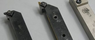
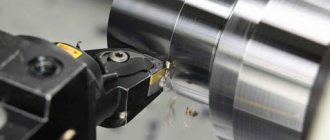
Thread cutting on a lathe is one of those operations for which various tools can be used. This problem is most often solved using a cutter. In addition to it, taps, dies, and special-purpose working heads are also used. In addition, on lathes this operation can be performed using knurling technology.
The process of cutting threads on a lathe with a cutter
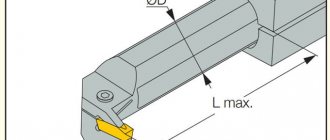
Design and dimensions
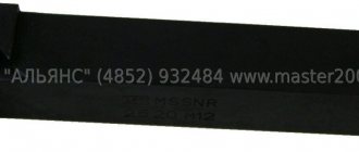
Carbide-tipped thread turning tools. Design and dimensions
GOST
18885-73
In place of MH 623-64; MH 624-64; MH 625-64; MH 626-64
ISS 25.100.10
By Decree of the State Committee of Standards of the Council of Ministers of the USSR dated June 8, 1973 No. 1429, the date of introduction was established
01.07.74
The validity period was removed by Decree of the USSR State Standard of 02.12.81 No. 655
1. This standard applies to general purpose turning thread cutters with carbide inserts.
(Changed edition, Amendment No. 1).
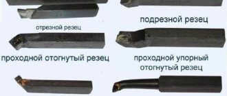
2. Cutters must be made of the following types:
1 - threaded for external metric thread;
2 - threaded for internal metric thread;
3 - threaded for external trapezoidal thread;
4 - threaded for internal trapezoidal thread.
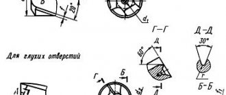
3. The design and main dimensions of the cutters must correspond to those indicated in the drawing. 1-4 and in table. 1-4.
Type 1
| With |
| r L |
Official publication Reproduction prohibited
N
Edition with Amendments No. 1, 2, approved in February 1981, June 1985.
(IUS 4-81, 9-85).
Table 1
mm
| Designation incisors | Apply bridge | Cutter section hb | L | T | Type of plates according to GOST 25398-90 | Thread pitch P |
| 2660-0001 | 16-10 | 100 | 1,5 | 0,5-2,5 | ||
| 2660-0003 | 20-12 | 120 | 3,0 | 11 | 0,8—3,0 | |
| 2660-0005 | 25-16 | 140 | 4,0 | 1,25-5 | ||
| 2660-0007 | 32-20 | 170 | 5,0 | 2-6 |
Note. Dimension g is made depending on the thread pitch (gish- = 0.144 S).
An example of a symbol for a cutter of type 1, with a cross-section hb = 20-12 mm, for a metric thread with a pitch P = 2 mm, with a plate made of hard alloy grade T15K6:
Cutter 2660-0003 2 T15K6 GOST 18885-73
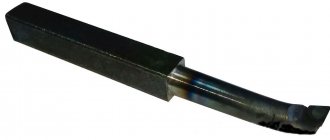
T i p 2
| Designation incisors | Apply bridge | Cutter section hb | L | / | d | T | Type of plates according to GOST 25398-90 | Step thread P | D hiring |
| 2662-0001 | 10-10 | 120 | 40 | 10 | 4 | 11 | 0,75-2,50 | 18 | |
| 2662-0003 | 12-12 | 140 | 50 | 12 | 5 | 1-3 | 24 | ||
| 2662-0005 | 16-16 | 170 | 60 | 16 | 9 | 1,5-4 | 30 | ||
| 2662-0007 | 20-20 | 200 | 80 | 20 | 12 | 2-5 | 42 | ||
| 2662-0009 | 25-25 | 240 | 100 | 25 | 14 | 3-6 | 52 |
An example of a symbol for a cutter of type 2, with a cross-section hb = 20-20 mm, for a metric thread with a pitch P = 3.5 mm, with a plate made of hard alloy grade T15K6:
Cutter 2662-00073.5 T15K6 GOST 18885-73
Crap. 3
| Incisors | Cutter section h ■ b | L | T | Type plates | Step threads R | |
| for right-hand thread | for left-hand thread | |||||
| Designation | Apply bridge | Designation | Apply bridge | |||
| 2664-0001 | 2664-0002 | 20-12 | 120 | 2,0 | 48 according to GOST 25422-90 | 2 |
| 2664-0003 | 2664-0004 | 3 | ||||
| 2664-0005 | 2664-0006 | 3,0 | 4 | |||
| 2664-0007 | 2664-0008 | 5 | ||||
| 2664-0009 | 2664-0010 | 25-16 | 140 | 4,0 | 6 | |
| 2664-0011 | 2664-0012 | 8 | ||||
| 2664-0013 | 2664-0014 | 6,0 | 10 | |||
| 2664-0015 | 2664-0016 | 32-20 | 170 | 12 | ||
| 2664-0017 | 2664-0018 | 8,0 | 16 | |||
| 2664-0019 | 2664-0020 | 40-25 | 200 | 10,0 | 32 according to GOST 25412-90 | 20 |
| 2664-0021 | 2664-0022 | 12,5 | 24 |
An example of a symbol for a type 3 cutter, with a cross-section hb = 2516 mm, for a right-hand trapezoidal thread with a pitch P = 6 mm, with inserts made of hard alloy grade T15K6:
Cutter 2664-0009 6 T15K6GOST 18885- 73
Type 4
I
Table 4
Dimensions in mm
| Incisors | Cutter section h ■ b | L | / | d | T | Type of plates according to GOST 25422-90 | Step threads R | D hiring | |
| for right-hand thread | for left-hand thread | ||||||||
| Designation | Apply bridge | Designation | Apply bridge | ||||||
| 2666-0001 | 2666-0002 | 1010 | 120 | 40 | 10 | 4 | 48 | 2 | 16 |
| 2666-0003 | 2666-0004 | 4 | |||||||
| 2666-0005 | 2666-0006 | 1212 | 140 | 50 | 12 | 4 | 2 | 22 | |
| 2666-0007 | 2666-0008 | 6 | 5 | ||||||
| 2666-0009 | 2666-0010 | 7 | 8 | ||||||
| 2666-0011 | 2666-0012 | 1616 | 170 | 60 | 16 | 6 | 3 | 30 | |
| 2666-0013 | 2666-0014 | 8 | 6 | ||||||
| 2666-0015 | 2666-0016 | 10 | 10 | ||||||
| 2666-0017 | 2666-0018 | 20 20 | 200 | 80 | 20 | 8 | 3 | 44 | |
| 2666-0019 | 2666-0020 | 10 | 8 | ||||||
| 2666-0021 | 2666-0022 | 12 | 12 | ||||||
| 2666-0023 | 2666-0024 | 25-25 | 240 | 100 | 25 | 6 | 4 | 62 | |
| 2666-0025 | 2666-0026 | 10 | 10 | ||||||
| 2666-0027 | 2666-0028 | 15 | 6 |
An example of a symbol for a type 4 cutter, with a cross-section hb = 1010 mm, for a right-hand trapezoidal thread with a pitch P = 2 mm, with a T15K6 grade hard alloy insert:
Cutter 2666-0001-2 T15K6 GOST 18885-73 (Changed edition, Amendment No. 1,2).
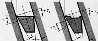
4. The values of the radii of roundings and chamfers not specified in this standard are accepted for technological reasons.
5. Structural elements and geometric parameters of the cutters are indicated in the appendix.
6. The form of sharpening the front surface and finishing of the cutting part are specified in Appendix 2 to GOST 18877-73.
7. Technical requirements - according to GOST 5688-61.
Technology for using taps and dies
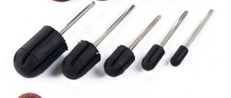
Using taps, which are a screw with several longitudinal grooves that form cutting edges and facilitate chip removal, predominantly metric threads are cut on a lathe in small-diameter holes. If machine taps are used for thread cutting, the operation is performed in one pass.
Machine taps differ from ordinary ones in that they consist of two parts - a tapping and a calibrating one. If ordinary taps are used to cut threads using a lathe, then the technology for performing this process involves the use of a set of tools. The set for cutting internal threads includes three types of taps: roughing, which does 60% of the work, semi-finishing (30%), finishing (10%). Sometimes in such a set there may be two tools: roughing, which does 75% of the work, and finishing, which accounts for 25% of the work. To distinguish a rough tap from a finishing one, just look at its cutting part: it is much longer than that of a finishing one.
Design of a tap for thread cutting
The speed of thread cutting on a lathe using taps can be quite high:
- 6–22 m per minute – for parts made of cast iron, bronze and aluminum;
- 5–12 m per minute – for steel workpieces.
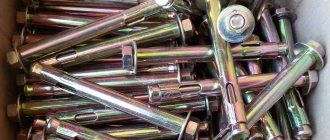
Using dies, which are a ring with an internal thread and several chip grooves, external threads are made on screws, bolts and studs. The surface of the part must be pre-ground to the required diameter, which must take into account the tolerance:
- 0.14–0.28 mm – for threads with a diameter of 20–30 mm;
- 0.12–0.24 mm – for threads with a diameter of 11–18 mm;
- 0.1–0.2 mm – for threads with a diameter of 6–10 mm.
The dies with which external threads are cut are secured in a special chuck (die holder) located in the tailstock quill of the lathe.
Threading dies
Using dies, threads are cut at the following speeds (their setting also takes into account minimal tool wear during operation):
- 10–15 m per minute – on products made of brass;
- 2–3 m per minute – on cast iron parts;
- 3–4 m per minute – on steel workpieces.
In order for the die to fit smoothly onto the part, a chamfer is removed at the end of the part, the height coinciding with the height of the thread profile.
What is an inch thread?
Threaded connections are characterized by the following factors: by type of fit: sliding, clearance, transitional, interference fit. According to the use of complementary parts: conventional direct connections and in combination with elements: ball, sleeve, spiral. Without or with a stopper.
- cylindrical or conical shape
- cutting method – external and internal cutting,
- type of direction of the screw line - left and right,
- approaches – multi-entry and single-entry,
- profiling parameter: metric, cylindrical, trapezoidal, conical pipe, conical inch, round, rectangular, thrust,
- Dimension – metric thread or inch pipe thread,
- purpose - for fastening, running threads, regulating,
- type of processing: cutting a part with a cutter, die, tap.
- LiveJournal
- Blogger
Bushing with inch connection
In modular slicing, the pitch is determined by modules. To convert to mm. "M" is multiplied by the number pi.
Pitch threads are measured in pitches (to determine the number of inches, pi is divided by pitch).
Options
GOST for inch threads 6257 - 81 determines the main precise parameters of the pass pitch and diameter. In this case, the measurement of the outer pipe diameter is equal to the distance between each upper point of the opposing ridges. The diameter of the internal lumen is measured from one point at the bottom of the groove cavity to the opposite point. The thread pitch is a constant value, it is measured by the distances between adjacent ridges or depressions.
Differences between metric and inch threads:
- metric dimensions - in mm, inch dimensions - in inches or their fractions,
- inch threads are characterized by sharper angles of inclination of crests and valleys,
- The threads have a rounded shape.
Upper angle size = 55 degrees, thread pitch is measured by the number of threads.
The following types of products are used in everyday life:
with a parameter of 1 inch - 14 threads, step length 1.814 mm, diameter ¾ or ½,
11 threads in 1 inch - with a pitch size of 2, 309, and a diameter of 1; 1 and ½; 1 and ¼.
Relation between inch and metric threads:
- LiveJournal
- Blogger
Table of ratio between inch and metric threads
Making pipe threads
Threading is done on a lathe with a cutter, as well as with the help of dies, combs and taps, manually or mechanically. To clarify the dimensions, you will need a thread gauge tool (comb, gauge) or a caliper.
Pipe thread pitch determination
When cutting metrically, you first need to determine the thread pitch: measure the distance separating the vertices, then divide by the number of threads.
It is important to check first the pitch and profile, then the dimensions of the internal and external diameters.
To find out the step using a ruler, or determine it with a caliper, you need to measure the length of two or three passing steps, then divide by the number of steps. When checking with a thread gauge, the teeth of the nail file should fit tightly and without gaps to the thread being measured.
The accuracy of measurements depends on the following conditions:
- degree of wear and cleanliness of the part;
- convenience of measurement operation,
- cleanliness and appearance of the instrument,
- correct use of the measuring instrument.
Using the inch method, calculate the number of threads per 1 inch of pipe. After processing, verification is required.
To determine the pitch of an inch thread using a fitting (coupling) with an internal thread of the required dimensions, you need to screw a bolt into the part. If it goes in smoothly, tightly, effortlessly, then the pitch and cutting diameter dimensions are selected correctly. To measure the external size of the ridges, screw-on parts of the nozzle are used. If the sizes do not match, use other calibers in turn until they match.
How to use a thread gauge? The plates that are included in the tool are applied to the external, then internal thread of the pipe. If the profile corresponds to the size of the file, it is clarified visually: the free clearance is examined. Exact match means the size parameters indicated on the files (plates) of the thread gauge.
Calipers and micrometers accurately measure only outer diameters, so a more acceptable option is to use a thread gauge.
To avoid mistakes, you need to measure each diameter of the part three times, calculate and select the average value.
To avoid mistakes, you need to measure each diameter of the part three times, calculate and select the average value.
- LiveJournal
- Blogger
Example of an adapter with applied internal and external threads