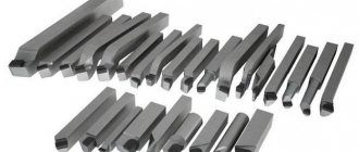
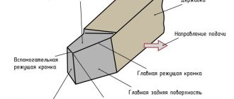
Shaped cutter for metal
can be used when processing open-type surfaces, as well as for creating grooves. The use of such tools makes it possible to create even a complex shaped profile of the workpiece. The use of shaped cutters is important for processing metal surfaces of workpieces that have a significant difference between length and width.
Shape cutters can have two types of teeth:
- backed;
- pointed.
In order for the profile of the backed cutter teeth to coincide with the shaped profile of the part, the rake angle of the cutter must be equal to zero. Any positive angle requires tooth adjustment. To ensure the correct indicators, before starting work it is necessary to check the shaped cutter against the template.
Photo No. 1: cutter with pointed teeth
Photo No. 2: cutter with backed teeth
To mill semicircular grooves and protrusions, as well as create roundings at the corners of a part, shaped cutters of radius, convex and concave types are used.
Radius shaped cutter
The radius shaped cutter is a universal product that can be used for processing grooves with internal and external curves. Manufactured according to GOST 9305-93.
The cutting part of the radius cutter allows you to perform not only cutting work, but also to select grooves and create a sculptural finish on the surface of the workpiece. This tool can be used both in manual machines and on automated equipment.
Photo No. 3: concave radius cutter
Photo No. 4: convex radius cutter
A radius cutter allows you to create complex lines on the surface of a product, but the tool wears out during operation. It is necessary to control this process and pay attention to the correct angle of inclination of the helix. Before you buy a cutter, you need to make sure the quality of the sharpening.
Depending on the purpose, a radius cutter can be:
- concave;
- convex;
- combined.
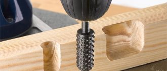
End mill design
In general, an end mill is a monolithic metal cylinder consisting of two parts: a driver (shank) for installation in equipment and a milling part with cutting elements (teeth) arranged in a spiral. Its main geometric parameters are the overall length, the diameter of the cutting part, as well as the diameter, type and length of the shank.
Shanks
In accordance with GOST 53937-2010, end milling machines, depending on their purpose and area of application, can be produced with the following types of shanks of various sizes:
- smooth cylindrical;
- cylindrical with thread;
- cylindrical with several types of flats;
- with Morse cones, complemented by threads and flats;
- with 7:24 cones for manual and automatic tool changing;
- with HSK hollow cone for manual and automatic tool changing.
To secure the end milling cutter into spindles and chucks with other mounting holes, adapter bushings are used. In practice, abbreviations are often used in the designation of shanks, for example, “end mill cutter” means “with a tapered shank,” and “KM2” is a tool with a Morse taper N2.
Download GOST 53937-2010
Cutting part
The design of the cutting part is of two types: all-metal and with inserted cutting elements. The cutting planes and the grooves separating them for removing chips bend around the cylindrical surface in a spiral in the right direction (the tool is also available with left-hand rotation). On their upper part there is either a sharp cutting edge, or closer to its end there are inserted cutting plates. All-metal milling cutters are usually made from high-speed steel. Coated carbide teeth are attached to the end mill body in the following ways:
- soldering;
- eccentrics;
- screws;
- special bolts with a wedge-shaped head.
The number of cutting planes determines how many metal cuts the milling tool makes in one revolution (approach). The most common are one-, two- and three-flute end mills (they are also called “single- (two-, three-, etc.) flute end mills”). High-pass end mills are used for finishing and milling hard and brittle materials.
As mentioned earlier, small end mills belong to the group of end mills. In this type of milling tool, the side cutting surface is supplemented with auxiliary cutting edges located at the end of the cutter.
Grooving, copying and key milling cutters also have additional cutting surfaces.
Convex shaped cutter
A convex shaped cutter is used to create internal roundings of grooves and protrusions. Product characteristics may vary depending on the complexity of the surface. All data can be found on the surface of the cutter itself.
According to GOST 9305-93, the diameter of a convex shaped cutter can be from 50 to 160 centimeters, the radius - from 1 to 25 millimeters.
Convex-shaped equipment is widely used on horizontal type machines and universal equipment that are used by machine-building enterprises. Made from high-quality steel, cutters can work even under intense loads without losing their qualities.
Angle shaped cutter
Angular shaped cutter is used for processing surfaces with complex profiles. Quite often, this type of equipment is used in tool production for milling chip grooves of various metal-cutting devices.
Photo No. 5: double-angle shaped cutter
Photo No. 6: single-angle shaped cutter
The most important difference between this type of milling products is their conical shape and teeth of different heights. The following types of angular shaped cutters are distinguished, depending on the location of the teeth and cutting edge:
- single-angle;
- symmetrical two-angle;
- asymmetrical two-angle;
- terminal
DISC SHAPED MILLS
Shaped
These are called cutters whose cutting edge or tooth profile has a shaped, complex contour. Disc shaped cutters are used for milling straight and helical grooves on prismatic and cylindrical parts, as well as on various cutting tools (drills, countersinks, reamers, taps, milling cutters, etc.). Milling cutters with pointed teeth are not used for this. After wear and tear for each resharpening, the back surface along the entire contour must be formed as if anew, which complicates the operation of such cutters. They are used for cutters with a simple shaped contour, the regrinding of which along the profile does not create great difficulties. Disc shaped cutters are usually made with backed teeth to obtain the required positive clearance angle. The main advantage of cutters with backed teeth is that their profile after regrinding along the front surface remains constant. The backed back surface of the tooth is formed as a result of uniform rotation of the backed tool relative to its axis and the translational movement of the backed tool in the radial direction towards the cutter. Whether this translational movement is uniform or not will result in different tooth lines in the cross section of the tool: a general second-order curve, an Archimedean or logarithmic curve, a circular arc or a straight line. In prefabricated disk cutters, the back surfaces of the teeth can be formed along a circular arc, eliminating the operation of backing. To do this, in the technological body, which can be combined with the working one, the rear surfaces are ground with a shaped cutter or ground around the circumference. After this, the teeth are rearranged in the working housing in the appropriate way, creating rear angles along the entire profile. The profiling of such cutters is different from the profiling of backed and pointed cutters. Currently, instruments are backed only using the Archimedes spiral. It is more technologically advanced than others, since it is formed as a result of two uniform indicated movements of the backing and backing tool. On existing turning and backing machines, these movements are easily implemented. The forward movement is produced from the cam. The back cam also moves along the Archimedes spiral. Its decline or rise is equal to the amount of backing of one cutter tooth. As a result, one cam can be used to grind cutters of different diameters and with different numbers of teeth, which is also a significant positive aspect of this curve. To create more optimal clearance angles on the side cutting edges, lateral and oblique relief are used, in which the uniform movement of the relief tool is directed along the axis of the cutter or at a certain angle to it. But with axial or oblique backing, the profile of the cutter teeth will change as it is sharpened, which is unacceptable or undesirable for shaped cutters. Therefore, such cutters are mainly radially backed.
Structural elements of disk shaped cutters. The structural elements of cutters include: outer diameter, mandrel hole diameter, tooth height and thickness, wall thickness, cutter width, cavity dimensions and number of teeth.
Cutter diameter.
Outer diameter of cutter: .
The diameter of the hole d
is equal to the diameter of the mandrel.
The height of the keyway h1
is taken according to the normals depending on
d
.
Wall thickness, taking into account stresses arising during heat treatment, T
= 6–12 mm.
Experience in designing cutters shows that D1
= (1.6 – 2) ·
d
, here a smaller coefficient is accepted for larger diameters.
H
–
tooth height.
Number of cutter teeth with
As the diameter increases, it usually decreases. This only works for shaped disc cutters with backed teeth. This is explained by the fact that usually such cutters have a large profile height and its change is not directly proportional to the change in the diameter of the cutter.
Milling cutter teeth profile.
Determining the tooth profile of disc shaped cutters is one of the main and most complex tool design tasks. The tooth profile is determined in the axial plane of the cutter. It represents a cross-sectional curve of the backed surface of a cutter tooth by the axial plane. In this plane, a backing cutter is installed when manufacturing the back surface of the teeth and a template for controlling the profile of the cutter teeth.
Profiling of disc shaped cutters for processing helical grooves.
When processing the surfaces of helical grooves, the profile of the initial surface of the tool and the profile of the cutter teeth, which has a rake angle equal to zero, differ from the profile of such grooves. This is explained by the fact that helical grooves are processed using disk tools (mills and grinding wheels) using the centerless bending method. In this case, there are no initial circles along which the product and the tool roll without sliding in a relative shaping motion, but the surface of the groove is formed in a relative motion as a result of a series of successive cuts by the cutting edges of various teeth in their different positions.
Manufacturing of shaped cutters
Making shaped cutters is a rather labor-intensive process that requires special attention when sharpening. Any correction of the profile leads to a limitation of the scope of application of the product.
The material used to create shaped cutters is high-speed steel. The use of hard alloys in the manufacture of these products is irrelevant, since this complicates the sharpening procedure and can affect the quality of the equipment. The design of shaped cutters can be solid or prefabricated.
To process parts with particularly complex profiles, special cutters are manufactured equipped with round-shaped carbide inserts that cannot be re-sharpened. The diameter of the plates varies from 12 to 16 mm. The plates are secured using two slats that are inserted into the grooves of the cutter body. To ensure the cleanliness of the treated surface, the displacement of the plates relative to each other should not exceed 2 mm.
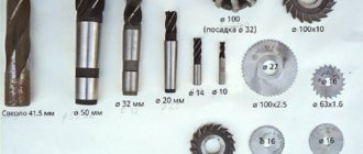
Classification of end mills
There is no special extended classification for end millers, therefore they are classified according to lists common to milling tools with the addition of their characteristic features. Below are the main sections of the classification used for various types of metal end mills:
By production purpose
In this section, the main feature is the type and shape of the surface being processed. Based on this, the following types of this tool are distinguished:
- general use;
- with end cutting part;
- for keyways (including for slots of segmental keys);
- for figured grooves;
- for shaped flat profiles;
- carbon copies.
By design
GOST obliges manufacturers to produce end mills of two types of lengths: normal and long and determines the ratio of the dimensions of the shank and the cutting part. But in addition to this, there are end mills on the market, both elongated and very short (popularly called “finger”). In addition to the types and length ratios, GOST defines the types of shanks (various types of conical and cylindrical), as well as size ranges of diameters. Most often in industrial production, an end mill with a conical shank is used.
State standards define only general requirements for milling tools. At the same time, global manufacturers offer various innovative designs. An example of these are modular end mills, in which the cutting part is attached to the shank using a high-precision screw connection. Another interesting development is a six-flute overrunning end mill with top and bottom bearings for finishing slots using a template.
According to the shape of the cutting surfaces
To form specific surface profiles of workpieces, in addition to general-purpose tools, a large group of shaped end mills was created. Among them, the main ones are radius and shaped groove milling tools, as well as milling cutters for 2D and 3D processing. The main types of end milling machines, classified according to the shape of the cutting surfaces, are:
- cylindrical;
- end;
- keyed;
- radius end mill;
- radius concave cutter;
- T-shaped cutter;
- cutter for dovetail groove;
- corner end mill;
- Conical and cylindrical end mills with straight and rounded ends.
By the number of cutting edges and direction of rotation
The process of burying a cutting edge into the metal and removing one layer of allowance with it is called “setting in.” The more cutting surfaces a router has, the more passes it makes per revolution. An end milling tool with one cutting surface is single-cut. If there is more than one surface, then the tool is multi-start (single-, double-start cutters, etc.).
In addition, there is an extensive classification of end mills based on the geometry and shape of the cutting surfaces, teeth and edges.