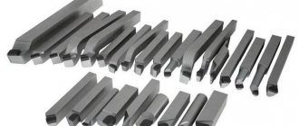
- Straight through turning tools and their purpose
Lathe cutter design
Different types of cutters for a lathe differ in shape, the presence of additional blades, and teeth. However, the overall design remains unchanged. The equipment consists of two main elements:
- Rod is another name for “holder”. A piece of equipment that is attached to equipment.
- Working part. The sharpened element of the cutter that comes into contact with the workpiece. Depending on the design features, the plate in contact with the workpiece may consist of many cutting edges and working planes.
When working with equipment for turning equipment, we must not forget about the importance of sharpening angles of the working part. There are three angles in total, changing which will affect the result.
The process of sharpening cutters for metal
To sharpen cutters, sharpening and grinding machines with a constant cooling function are used. The main surface of the product is first sharpened, then the back and additional surfaces. At the final stage, the original configuration of the front face is returned.
Photo No. 11: the process of sharpening the cutter
For the operation, two grinding wheels are used: silicon carbide and electrocorundum. Silicon carbide is suitable for machining high-speed steel products. Electrocorundum is made from carbide materials. To check the degree of sharpening, special templates are used.
Cutter geometry
There are different types of cutters, which differ in size, shape of the holder and the number of planes on the working head. For example, the rod for securing the equipment can be round, rectangular, or square. The working element of the device is a set of surfaces
— Incisors are divided into right-handed and left-handed. The difference lies in how the cutting edge is positioned relative to the holding part.
Types of planing cutters
Planing products differ from turning products by having a backward curved head and a top that does not coincide with the reference plane of the tool. This design is explained by the technological features of metal processing. If the cutter were not curved, it would break under the pressure of the removed layer of metal.
Image No. 3: types of planing cutters (diagram)
According to the type of work performed, tools are divided:
- on passages for horizontal planes;
- cutting for ledges;
- for cutting workpieces;
- shaped for working with complex surfaces.
Classification of cutters for turning
There are state standards that describe the classification of turning tools. One of the classifications is the division according to the type of processing of metal surfaces:
There is a division according to the type of material from which the working part of the equipment is made. A separate classification concerns the integrity of the equipment design:
- One-piece fixtures. They are accessories for lathes made from alloy steel. Models made of tool steel are rare.
- Devices with additional plates. They are made at the factory from different types of hard metals and alloys.
- Models with removable plates. They are fixed to the holder using screws. Rarely used during serial processing of metal parts.
The main classification is the division of devices into separate types according to shape and design. We need to talk about them separately.
Cutting speed, feed rate and depth of cut
Determination of cutting speed, feed rate and chip thickness
The cutting speed of any operation consisting of removing chips or cutting metal is expressed in meters per minute or millimeters per second. For lathes, the cutting speed is equal to the length traversed by the cylindrical (with cylindrical turning) or end (with frontal turning) surface of the product per unit time along the cutter blade. If one could accurately measure the length of chips removed by a cutter in a minute (or second), it would represent the cutting speed.
The feed rate or simply feed (feed) during turning is the amount of movement of the cutter along the workpiece per one revolution of the latter. If, for example, when turning a shaft, the feed is 0.5 mm, this means that when the product makes 100 revolutions, the caliper will move by 0.5 x 100 = 50 mm. The expressions often used are: “large” or “large” feed, “small” or “thin” feed. These expressions make sense only when talking about machines of approximately the same power. It is clear that the same feed can be “small” for a large machine and “large” for a low-power machine.
The cutting depth is the thickness of the metal layer removed by the cutter; This is sometimes also the name for the thickness of the chips removed, although these values are not quite the same due to the deformation of the metal during cutting. Let us assume, for example, that a steel blank with a diameter of 50 mm needs to be turned on a lathe to a diameter of 47 mm in one pass. It is clear that the cutting depth should be (50 - 47) /2 = 1.5 mm.
Time Element
One of the main factors that determines the productivity of a machine or workshop is time. The time at which the metal is removed from the product depends on the time it takes to completely process it. The amount of chips removed depends, in turn, on three elements - depth of cut, feed rate and cutting speed. Let's take turning as an example.
- Let's assume that it is necessary to reduce the diameter of the product from 50 mm to 47 mm, i.e. The cutting depth should be 1.5 mm. If the cutter can take such chips in one pass, then there is no point in making two passes, removing 0.75 mm chips, since turning would require twice as much time. Therefore, the first productivity factor is the depth of cut.
- If, with one revolution of the product, the cutter is fed by 0.4 mm, while it could be given a feed of 0.8 mm, then to pass a certain length, twice the number of revolutions of the product will be required, in other words, all other things being equal, twice as long. Thus, the feed rate is the second factor affecting the processing speed.
- Let the diameter of the product be 50 mm and its rotation speed 65 per minute. The cutting speed is obviously: π ✖ 0.050 ✖ 65 = 10 meters per minute. If the cutter can operate (without abnormally frequent regrinding) at a cutting speed of 20 meters/min, then it is uneconomical to give the machine spindle only 65 rpm. Therefore, the third productivity factor is cutting speed.
The task of productive and economical workshop operation therefore comes down to the skillful selection of cutting speed, feed rate and depth of cut for each job and the selection of the appropriate machine. Successful selection of these elements requires a lot of experience. It’s easier to find them by counting using known formulas.
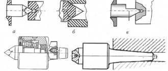
Boring cutters for through holes
This is equipment for industrial equipment. It is used for boring holes created by drilling. The depth of machining of the holes depends on the length of the part fixed in the caliper. The element with the cutting edge has a bent head. The thickness of the material removed by the cutting edge is almost equal to the bend. The maximum length of the holding part is 300 mm.
Making your own cutters: a step-by-step guide
The main thing is to use only tool steel that has sufficiently high performance characteristics.
Experts recommend choosing an alloy or high-speed carbon version.
Selecting the required configuration of files or rasps
The selection of these parts will be easier if the owner knows in advance exactly what tasks he faces. After this, choosing the length, shape and size will not be difficult. Here are some tips.
- If you need to file up to 5-10 mm in thickness, it is better to stop at cut number 0 or 1.
- The processing accuracy should be within 0.01-0.02 mm.
- It is much easier to choose devices based on length.
The main guideline is the dimensions of the surface that needs to be sawed. The larger this parameter, the larger the device itself should be.
You can use a specific formula to make the calculation more accurate. We add 15 cm to the length of the surface of the product. We get the value, which will be the length of the working surface of the file or rasp. The main thing is that when working, the tool is passed over the entire workpiece.
Fastening cutting parts
Homemade tools do the same as professional ones. The optimal solution is self-tapping screws. The higher quality the product, the better.
Tool sharpening
Only regular sharpening of the cutters will allow you to obtain the most accurate results. The need for the procedure arises not only for instruments that have disposable carbide inserts. The work is performed by specialized machines when it comes to large-scale manufacturing enterprises.
There are practically no restrictions on the method for home use. Suitable for use with conventional sharpening wheels and chemically active reagents. Machines for universal, specialized purposes are a cheap option that maintains efficiency.
When processing the back of a tool, there are three main stages.
- Maintaining the same angle as the holder itself at the back. The increase in the indicator compared to the rear cutting angle is 5 degrees.
- The second stage involves processing the surface of the cutting insert itself from the back. Here we need to keep the excess equal to 2 degrees.
- Finishing is the third stage. It is needed to form the required rear angle.
The front surface also goes through several processing stages.
Refinement and polishing
This is done with carbide on a special cast iron disk. The device rotates, maintaining a speed of up to 1-2 m/s. The direction of rotation of the disk itself is towards the working edge, away from the supporting part of the tool.
Consistently grind the blades and tool surfaces. The incisors are almost brought to a shine, and any irregularities are removed.
Why is fine-tuning needed? A tool becomes dull and wears out over time if it is used often enough. The reason is that the plate rubs against the workpieces and chips. If the plate is smoother, there will be less friction. In this situation, tool wear slows down.
The finishing process has other features:
- When finishing, abrasive pastes are used, the main component of which is boron carbide.
- Finishing involves wetting the tool with kerosene.
- Then the paste is applied to the surface in a zigzag manner.
- The instrument is brought to the disk.
- GOI paste can be used in conjunction with kerosene.
- Kerosene is not a mandatory step when using modern lubricants.
It is important to install the support table correctly. After its installation, in comparison with the middle part of the disk, the cutter blades with the part are on the same lines, or lower. The rotation of the disk is directed towards the threaded plate.
The paste particles begin to be crushed when the tool is pressed and finishing is started. The cutter has no chips or abrasions when passing through the edges. Irregularities on the incisal surface are eliminated thanks to the very grains of the paste.
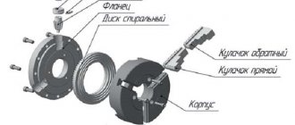
Prefabricated cutters
Perform various technological operations. The design allows you to attach different carbide inserts to the holder. The presence of several working elements allows you to increase the versatility of the device. The cutters, which are assembled from different plates, are fixed in the spindles of equipment controlled by a CNC system. Using prefabricated devices, holes are machined, contours are made, and grooves are selected.
What are the current standards and the explanation of their markings?
The main standard by which turning tools are manufactured is GOST:
- Cutting and groove - GOST 18874-73.
- Boring - GOST 18872-73.
- Walkthroughs - GOST 18871-73.
- Shaped - GOST 18875-73.
- Threaded - GOST 188885-73.
Marking according to the material of the working part:
- Tungsten - VK8, VK2.
- Titanium tungsten - T5K10, T15K6, T30K4.
- Titanium-tantalum-tungsten - TT7K12, TT8K6.
- High carbon steel - U10A, U12A.
- High-speed steel of normal efficiency - P9, P12, P18.
- High-performance high-speed steel - R18F2, R18F4, R6M3.
This is interesting: How to restore chrome: cleaning and restoration of chrome coating