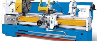
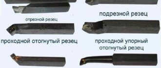
- Straight through turning tools and their purpose
Design features of turning tools
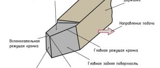
Each turning tool consists of two parts.
- Holder. Can be square or rectangular. With its help, the cutter is secured in the mounting sockets of the machines. GOST establishes the following standard dimensions of holders.
Square - 4*4, 6*6, 8*8, 10*10, 12*12, 16*16, 20*20, 25*25, 32*32, 40*40 mm.
- Rectangular - 16*10, 20*12, 25*16, 25*20, 50*25, 40*32, 50*32, 50*40, 63*50 mm.
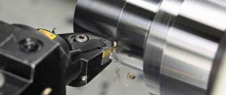
Image #1: Lathe cutter design
Nuances of choosing a cutter
When purchasing cutting tools, you need to pay attention to the following criteria:
- A type of cutting tool. Different types of cutters differ in profile shape, determined by the technical features of carbide inserts.
- Dimensional characteristics. The different dimensions of products processed on a lathe determine the dimensions of the cutting tool. For modern types of cutters, you can select workpieces with distinctive dimensional characteristics.
- Back angle value. This indicator affects the accuracy of finishing of the material. The surface cutting cleanliness is directly proportional to the clearance angle. This parameter is taken into account when turning metal workpieces with soft surfaces.
- Accuracy class. This parameter is used to calculate the accuracy of the cutting performed. According to GOST 9253-59, 3 main accuracy classes are established for plates. When measuring this parameter, it is possible to cut workpieces with tools with different tolerance values.
If these criteria are not taken into account, then the thread cutters will not be able to be firmly fixed on the lathe and produce precise processing of metal parts.
When purchasing cutting tools, it is important to choose the right inserts. These parts are made of hard metal alloys. The ratio of metals determines the operating characteristics of the cutting tool. There are 2 main types of plates:
- With increased strength. They are resistant to vibration, shock and other physical stress that occurs during cutting. It is recommended to purchase this category of plates if you need to cut a large amount of metal from the workpiece.
- With increased heat resistance. They can withstand high temperatures that arise during long-term processing of workpieces and exposure to frictional forces. Heat-resistant plates are fixed mechanically. They are used when working at high speeds.
Materials of manufacture are indicated on the markings of carbide inserts. Each alloy has a unique image. In the manufacture of cutting parts, tungsten is used, which has high strength and resistance to large temperature changes. Additionally, titanium carbide or cobalt can be used. Plates made of ceramic materials are used during finishing or semi-finishing of metal products. They can be used for cutting workpieces made of heat-resistant alloys. The percentage of these components determines the category of replacement plates. On the marking, titanium is designated by the letter “T”, cobalt by the symbol “K”. Example of marking: T14K7 (percentage of titanium carbide - 14%, cobalt - 7%).
For large volumes of turning work, it is recommended to purchase a set of turning tools with replaceable inserts, which will allow you to quickly adjust the tool during various technological operations. When choosing sets, it is important to consider the manufacturer's brand. The most popular replacement plates on the market are from the following companies:
- LLC “Instrument-Service”: a Ukrainian company that produces parts for cutting tools.
- Interpipe: is the largest organization for the production of pipe and threaded connections in Eastern Europe. The products are manufactured at the Novomoskovsk pipe plant, located in the Ukrainian city of Dnepr.
- BDS-Machinen: German company producing devices and parts for magnetic drilling machines.
- Proxxon: an organization that develops parts for cutting small workpieces. Production takes place in Germany.
- Ceratizit: a company producing metal-cutting tools and their main components. The headquarters is located in Luxembourg.
The cost of a set of turning tools depends on the manufacturer's costs and the financial policies of suppliers. Imported parts have the highest price. The average price of a set is 15,000 rubles. Additionally, you can purchase certain types of plates. Their average price is 164 rubles.
Geometry of turning tools
Image No. 2: turning tool geometry
Let's talk about the angles of the incisors and their purposes.
- Back auxiliary angle (α1). As it decreases, the friction force between the rear plane of the tool and the workpiece decreases.
- Apex angle (ε). Formed between the cutting edge and the rear auxiliary plane. The larger this angle, the better the heat removal conditions and the higher the strength of the cutter.
- Auxiliary plan angle (ϕ1). Its size varies from 10 to 30°. As the angle decreases, the cleanliness of the treatment improves, but the friction force increases.
- Leading angle (ϕ). Its size varies from 20 to 90°. The length and width of the cut depend on the size of the angle. The smaller ϕ, the lower the temperature and cutting force. The cleanliness of the processing is also improved. But as the angle decreases, vibration and radial cutting force increase.
- Cutting angle (δ). Formed between the rake surface and the cutting plane.
- Basic rake angle (γ). Its size varies from -5 to +15°. As the angle increases, it is easier for the tool to cut into the metal, chip removal is improved, and the cutting force, deformation of the machined surface, and power consumption are reduced. However, this reduces heat dissipation and reduces the service life of the cutting edge.
- Taper angle (β). Formed between the front and main back surfaces. Affects the sharpness and strength of the tool.
- Main relief angle (α). Its size varies from 6 to 12°. As the angle decreases, the friction force between the part and the back surface of the cutter decreases. This improves heat dissipation and extends the service life of the tool, but the cleanliness of the machined surface deteriorates.
- Angle of inclination of the main cutting edge (λ). Affects the direction of chip removal. At positive λ and λ = 0°, the chips move towards the machined surface. Cutters with positive λ (12–15°) are used when processing workpieces made of heat-resistant and hardened steels. For universal turning tools, λ = 0°. Cutters with negative λ are used for finishing.
Lathe cutter design
The basis of the cutter is a rod fixed in the cutter holder. A cutting element, the head, is installed in the front part of the rod. The cutter has several surfaces. Chips run off the front surface. The rear surfaces, main and auxiliary, face the part. The main cutting edge, lying at the intersection of the front and main back surfaces, cuts the metal.
Classification of incisors
Turning cutters differ:
- In the direction of delivery. The right cutters move during the working feed from the tailstock to the front (from right to left). The left is making the opposite labor movement.
- According to the type of working head: straight, bent incisors.
- Turning cutters are produced as one-piece and composite ones. The compound cutter is made with an attached head made of expensive steel.
- According to the geometric section of the rod.
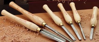
The cutting part of turning tools can be made of carbon and carbide steels (“Pobedit”), diamond and mineral-ceramic materials.
Determining the working direction of the cutter is simple. When installing, the cutting edge should be directed towards the workpiece.
Types of turning tools
Walkthroughs. Used for processing external cylindrical surfaces. Performed for working passage in both directions. A bent cutter can process ends during transverse feed.
Passing persistent. They are used to process stepped parts and trim the ends. Such cutters ensure perpendicularity of adjacent planes of steps. Can be either right or left. They are made of hard alloys by soldering onto a rod.
Trimming. They machine the stepped profile of a part, trim the ends and beads, and are capable of processing external cylindrical surfaces. The carbide cutting part is made by soldering onto the base.
Boring. The diameter of the holes prepared by drilling is increased (bored). Boring is carried out in several stages with the formation of a stepped surface at the end. Then, using a cross feed, the steps are cut until perpendicular surfaces are formed.
Cut-off. The finished part is separated from the workpiece, grooves and grooves are machined. Processing is carried out at right angles to the part with a working part made of high-speed and hard alloys.
Cutting internal and external threads is carried out using thread cutters . Shaped sharpen surfaces of complex shapes and grooves.
Automatic turret cutters
They are used on automatic turret lathes in mass production.
Longitudinal turning cutters. Automatic cutters made of high-speed steel are made by soldering or mechanically attaching the cutting part to a rod. The tool, depending on the installation in relation to the part, can be radial or tangential, which is ensured by special sharpening, as well as the design of the holder installed in the turret. By rotating the holder, the cutters are installed at different angles in relation to the workpiece.
Read also: Washing machine motor control diagram
Grooving and parting cutters. Installed on transverse supports of automatic machines. They have a design similar to cutters for conventional lathes. Since automatic machines mainly work with bar blanks, the cutting cutter, having a specific sharpening, not only cuts off the finished part, but also processes the end of the next part.
Marking of turning tools, meaning of numbers and symbols
According to the standard, the marking of turning tools may include 9 or 10 characters.
- The first is the method of attaching the cutting insert.
- The second is its shape.
- The third is the type of cutter.
- The fourth is the rear corner of the cutting insert.
- Fifth - cutting direction.
Image No. 6: possible values of parameters 1–5
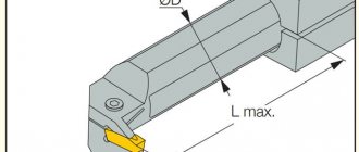
- The sixth is the height of the holder.
- The seventh is the width of its tail section.
- The eighth is the total length of the incisor.
- The ninth is the size of the cutting plate.
Image No. 7: possible values of parameters 6–9
- The tenth is indicated if necessary. Indicates the accuracy of some cutter parameters.
Image No. 8: possible values for parameter 10
To get a consultation
regarding tools, processing methods, modes, or select the necessary equipment, you can contact our managers or CAD department
You can also select and purchase cutting tools and equipment for the machine, made in Taiwan, Israel
By submitting an application, you agree to the privacy policy
Turning cutters are the main working tool of wood and metalworking machines, through which the processed workpieces are given the required shape and size. The classification of turning cutters is carried out according to factors such as purpose, type of processing, method of feeding and fastening, which we will discuss in more detail in this article.
The publication discusses the types of turning cutters and their design, provides recommendations for choosing a tool and the technology for its installation, and also provides instructions by following which you can properly sharpen the cutter with your own hands.
Cutting modes
Cutting modes are a set of parameters that determine the conditions for processing parts using a turning tool. The cutting process is influenced by the following factors:
- Cutting speed is the path of movement of the machined surface of the workpiece relative to the cutting edge per unit time. Measured in m/min or m/s. In the drawings it is designated by the Latin letter V.
- Feed is the path traveled by the cutting edge in 1 stroke or revolution of the workpiece being processed. Measured in mm/rev. In the drawings it is marked with the Latin symbol S.
- Depth of cut is the distance between the machined and machined surfaces. It shows the amount of metal layer being removed. In the diagrams it is denoted by the Latin letter t.
- The cross-sectional area of the cut layer is the product of the cutting depth and the feed. It is a nominal value and affects the presence of roughness. In the diagrams it is indicated by the Latin symbol f.
These parameters are tabular values and are specified in GOST 25762-83.
Download GOST 25762-83
Each type of cutting tools with mechanically fastened inserts has additional cutting modes. Cutting cutters carry out transverse movements, boring tools move longitudinally relative to the surface of the workpiece. During operation, the average speed of the cutting edges is tenths of mm. The feed is 0.1 mm/rev.