Modern types of welding open up many possibilities for the master, allowing professionals and amateurs to realize their ideas. Using argon arc welding, you can join dissimilar metals, and using a budget inverter, you can weld a fence in your dacha. But sometimes welding equipment and components for them are not enough for full-fledged work; it is important to learn how to make and understand welding drawings. In them you can find out all the comprehensive information about the metal that needs to be welded, its thickness, characteristics and locations of future joints.
A drawing is a full-fledged document issued for one specific part or an entire metal structure. It contains all the information a welder might need. Reading welding blueprints proficiently is a must-have skill for any welder looking to build a career in the profession. In our article you will learn what is needed to decipher seams in drawings and what signs are used for this, we will also give several examples.
9.1. The concept of types of products and design documents
A product is any item or set of production items to be manufactured at an enterprise.
GOST 2.101-88* establishes the following types of products:
- Details;
- Assembly units;
- Complexes;
- Kits.
When studying the Engineering Graphics course, two types of products are offered for consideration: parts and assembly units.
A part is a product made from a material that is homogeneous by name and brand, without the use of assembly operations.
For example: a bushing, a cast body, a rubber cuff (unreinforced), a piece of cable or wire of a given length. Parts also include products that have been coated (protective or decorative), or manufactured using local welding, soldering, and gluing. For example: a body covered with enamel; chrome-plated steel screw; a box glued together from one sheet of cardboard, etc.
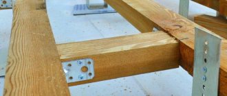
Assembly unit is a product consisting of two or more component parts connected to each other at the manufacturer by assembly operations (screwing, welding, soldering, riveting, flaring, gluing, etc.). For example: machine tool, gearbox, welded body, etc.
Complexes are two or more specified products not connected at the manufacturing plant by assembly operations, but intended to perform interrelated operational functions, for example, an automatic telephone exchange, an anti-aircraft complex, etc.
Kits are two or more specified products that are not connected at the manufacturing plant by assembly operations and represent a set of products that have a general operational purpose of an auxiliary nature, for example, a set of spare parts, a set of tools and accessories, a set of measuring equipment, etc.
The production of any product begins with the development of design documentation. Based on the technical specifications, the design organization develops a preliminary design containing the necessary drawings of the future product, an explanatory note, and analyzes the novelty of the product, taking into account the technical capabilities of the enterprise and the economic feasibility of its implementation.
The preliminary design serves as the basis for the development of working design documentation. A complete set of design documentation determines the composition of the product, its structure, the interaction of its components, the design and material of all its parts and other data necessary for the assembly, manufacture and control of the product as a whole.
Assembly drawing is a document containing an image of an assembly unit and the data necessary for its assembly and control.
A general drawing is a document that defines the design of a product, the interaction of its components and the principle of operation of the product.
Specification is a document defining the composition of an assembly unit.
The general drawing has the assembly unit number and SB code.
For example: assembly unit code (Figure 9.1) TM.0004ХХ.100 SB the same number, but without a code, has a specification (Figure 9.2) of this assembly unit. Each product included in the assembly unit has its own position number indicated on the general view drawing. By the position number in the drawing you can find in the specification the name, designation of this part, as well as the quantity. In addition, the note may indicate the material from which the part is made.
Examples of symbols
To make it clearer for you and you can quickly understand all the notations, we will give several simple and illustrative examples. So, let's begin.
Example No. 1
In the picture above you see a butt seam in which one edge has a curved bevel. The connection itself is double-sided, made by manual arc welding. There is no gain on either side. On the front side the seam roughness is Rz 20 µm, and on the back side it is Rz 80 µm.
Example No. 2
Here you can see that the seam is corner and double-sided, it has no bevels or edges. This connection is made by automatic welding and using flux.
Example No. 3
Here we have a butt seam again, but without bevels or edges. The connection is one-sided, with a lining. The seam is made using heated gas and welding wire.
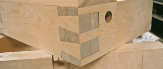
Example No. 4
In the fourth example, the seam is a T-joint and has no bevels or edges. It is intermittent and performed using a bilateral method. The seam seems to be in a checkerboard pattern. The work was performed using RDS in a gas environment and using a non-consumable metal rod. The leg of the seam is 6 millimeters, and the length of the seam is 50 millimeters, in increments of 100 millimeters (indicated by the letter “Z”). t w is the length of the seam, and t pr is the length of the step of the intermittent connection.
Example No. 5
In our last example, the seam is overlapped and has no bevels or edges. It is also single-sided and is performed by manual gas-shielded arc welding using a consumable rod. The welded connection is made along an open line. The leg of the seam is 5 millimeters.
9.2. Sequence of execution of drawings of parts
A part drawing is a document containing an image of the part and other data necessary for its manufacture and control.
Before completing the drawing, it is necessary to find out the purpose of the part, design features, and find mating surfaces. On the training drawing of the part, it is enough to show the image, dimensions and grade of material.
When drawing a part, the following sequence is recommended:
- Select the main image (see section 2).
- Set the number of images - views, sections, sections, extensions that clearly give an idea of the shape and size of the part, and supplement the main image with any information, remembering that the number of images in the drawing should be minimal and sufficient.
- Select the image scale according to GOST 2.302-68. For images on working drawings, the preferred scale is 1:1. The scale in the part drawing does not always have to match the scale of the assembly drawing. Large and simple details can be drawn on a reduction scale (1:2; 1:2.5; 1:4; 1:5, etc.), small elements are best depicted on an enlargement scale (2:1; 2.5 :1; 4:1; 5:1; 10:1; etc.).
- Select drawing format. The format is selected depending on the size of the part, number and scale of images. Images and inscriptions should occupy approximately 2/3 of the working area of the format. The working field of the format is limited by a frame in strict accordance with GOST 2.301-68* for the design of drawings. The main inscription is located in the lower right corner (on A4 format the main inscription is located only along the short side of the sheet);
- Layout the drawing. To rationally fill out the format field, it is recommended to outline the overall rectangles of the selected images with thin lines, then draw the axes of symmetry. The distances between the images and the format frame should be approximately the same. It is selected taking into account the subsequent application of extension, dimension lines and corresponding inscriptions.
- Draw the detail. Apply extension and dimension lines in accordance with GOST 2.307-68. After drawing the part with thin lines, remove the extra lines. Having chosen the thickness of the main line, trace the images, observing the ratios of the lines in accordance with GOST 3.303-68. The outline must be clear. After tracing, complete the necessary inscriptions and put down the numerical values of the dimensions above the dimension lines (preferably font size 5 according to GOST 2.304-68).
- Fill out the title block. In this case, indicate: the name of the part (assembly unit), the material of the part, its code and number, who and when the drawing was made, etc. (Figure 9.1)
Stiffening ribs and spokes are shown unshaded in longitudinal sections.
Figure 9.1 – Working drawing of the “Case” part
Creating a drawing from an assembly.
To create a drawing, click: “File, create drawing from assembly” . Select a template for the drawing and sheet format “A3-SPECIFICATION-L1-G” .
Sheet format for creating a SolidWorks assembly drawing
These drawing format templates for SolidWorks according to GOST are available.
And click OK. The drawing sheet opened.
9.3. Applying dimensions
Dimensioning is the most critical part of working on a drawing, since incorrectly placed and extra dimensions lead to defects, and lack of dimensions causes production delays. Below are some recommendations for applying dimensions when drawing parts.
The dimensions of the part are measured using a meter on the drawing of the general view of the assembly unit, taking into account the scale of the drawing (with an accuracy of 0.5 mm). When measuring the largest thread diameter, it is necessary to round it to the nearest standard, taken from the reference book. For example, if the diameter of a metric thread is measured to be d = 5.5 mm, then it is necessary to accept an M6 thread (GOST 8878-75).
9.3.1. Size classification
All sizes are divided into two groups: basic (conjugate) and free.
The main dimensions are included in the dimensional chains and determine the relative position of the part in the assembly; they must ensure:
- location of the part in the assembly;
- precision of interaction of assembled parts;
- assembly and disassembly of the product;
- interchangeability of parts.
An example is the dimensions of the female and male elements of mating parts (Figure 9.2). The common contacting surfaces of the two parts have the same nominal size.
Free dimensions are not included in the dimensional chains of the part. These dimensions determine those surfaces of the part that do not connect with the surfaces of other parts, and therefore they are made with less accuracy (Figure 9.2).
A – covering surface; B – covered surface; B - free surface; d – nominal size Figure 9.2
9.3.2. Dimensioning methods
The following sizing methods are used:
- chain;
- coordinate;
- combined.
With the chain method (Figure 9.3), the dimensions are placed sequentially one after another. With this sizing, each roller step is processed independently, and the technological base has its own position. At the same time, the accuracy of the size of each element of the part is not affected by errors in the execution of previous dimensions. However, the total size error consists of the sum of the errors of all sizes. Drawing dimensions in the form of a closed chain is not permitted, except in cases where one of the dimensions of the chain is indicated as a reference. Reference dimensions in the drawing are marked * and written in the field: “* Dimensions for reference ” (Figure 9.4).
Figure 9.3
Figure 9.4
With the coordinate method, dimensions are set from selected bases (Figure 9.5). With this method, there is no summation of sizes and errors in the location of any element relative to one base, which is its advantage.
Figure 9.5
The combined sizing method is a combination of chain and coordinate methods (Figure 9.6). It is used when high precision is required in the manufacture of individual elements of a part.
Figure 9.6
According to their purpose, dimensions are divided into overall, connecting, installation and structural.
Overall dimensions determine the maximum external (or internal) outlines of the product. They are not always applied, but are often listed for reference, especially for large cast parts. The overall dimensions are not applied to bolts and studs.
Connecting and installation dimensions determine the dimensions of the elements by which this product is installed at the installation site or connected to another. These dimensions include: the height of the center of the bearing from the plane of the base; distance between hole centers; diameter of the circle of centers (Figure 9.7).
A group of dimensions that determine the geometry of individual elements of a part intended to perform a particular function, and a group of dimensions for elements of a part, such as chamfers, grooves (the presence of which is caused by processing or assembly technology), are performed with varying accuracy, therefore their dimensions are not included in one dimensional chain (Figure 9.8, a, b).
Figure 9.7
| Wrong | Right |
Figure 9.8, a
| Wrong | Right |
Figure 9.8, b
Types of seams according to GOST standards (squares 2 and 3 examples)
Possible methods of connecting two elements are closely discussed in GOSTs 14771-76 and 5264-80. There are the following types of welding joints:
- C – butt weld . The two elements being connected are in the same plane and at the same level. They are connected to each other by adjacent ends. This is one of the most popular connection options. Its peculiarity lies in the fact that the mechanical characteristics of the weld are very high, and the appearance of the finished structure is aesthetic. Along with the positive aspects, there are also negative ones. This type of connection remains technically difficult. It can only be performed qualitatively by experienced specialists.
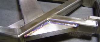
- T – tee seam . This implies a connection of two elements located at an angle of 90 degrees relative to each other, and the junction has a T-shaped configuration. This is the most rigid connection option of all those considered. Therefore, it is not used in cases where some elasticity is important for the finished structure.
- N – lap seam . Two workpieces are located parallel, but not in the same plane. They are in contact with some overlap of the plane. A fairly strong and reliable connection method, but in terms of rigidity it is inferior to the T-type version.
- U – fillet weld . The ends of two workpieces are positioned at an angle of 90 degrees. The ends melt, resulting in a fairly strong and rigid connection.
- O – special types . This designates all other options for welding workpieces that are not described in the standard.
Both GOST standards mentioned at the beginning of the section have common features and overlap with each other. For manual arc connection according to GOST 5264-80:
- C1 – C40 butt;
- U1 – U10 corner;
- H1 – H2 overlap;
- T1 – T9 tee.
Performing welding work in an inert environment in accordance with GOST 14771-76:
- U1 – U10 corner;
- C1 – C27 butt;
- H1 – H4 overlap;
- T1 – T10 tee.
The example above contains the numbers just discussed. The second square contains information on the standard used - 14771-76. The third square describes the connection method - double-sided T-joint without beveled edges.
9.5. Making a drawing of a part that has the shape of a body of revolution
Parts that have the shape of a body of rotation are found in the vast majority (50-55% of the original parts) in mechanical engineering, because rotational movement is the most common type of movement of elements of existing mechanisms. In addition, such parts are technologically advanced. These include shafts, bushings, disks, etc. processing of such parts is carried out on lathes, where the axis of rotation is located horizontally.
Therefore, parts having the shape of a body of rotation are placed on the drawings so that the axis of rotation is parallel to the main inscription of the drawing (stamp). It is advisable to place the end of the part, taken as the technological base for processing, on the right, i.e. the way it will be positioned during processing on the machine. The working drawing of the bushing (Figure 9.9) shows the execution of a part that is a surface of rotation. The outer and inner surfaces of the part are limited by surfaces of rotation and planes. Another example could be the “Shaft” part (Figure 9.10), limited by coaxial surfaces of rotation. The center line is parallel to the title block. Dimensions are given in a combined way.
Figure 9.9 - Working drawing of a part of the surface of rotation
Figure 9.10 — Working drawing of the “Shaft” part
9.6. Making a drawing of a part made from sheet metal
This type of parts includes gaskets, covers, strips, wedges, plates, etc. Parts of this shape are processed in various ways (stamping, milling, planing, cutting with scissors). Flat parts made of sheet material are usually depicted in one projection, defining the contour of the part (Figure 9.11). The thickness of the material is indicated in the title block, but it is recommended to indicate it again on the image of the part, on the drawing - s3 . If the part is bent, then a development is often shown in the drawing.
Figure 9.11 - Drawing of a flat part
Assembly Properties in SolidWorks
To fill in the properties, click on the file properties icon...
File properties icon in SolidWorks
A window opens to fill in the properties. Fill in the properties on the “Configuration” . We enter the designation: “3DDD.001.01.000 SB” , and the name: “Frame” .
Assembly Properties in SolidWorks
Also at the end of the properties window, enter the properties in the format line: “A3” .
Proceed to create an assembly drawing.
9.7. Execution of a drawing of a part manufactured by casting, followed by machining
Molding by casting allows you to obtain a fairly complex shape of a part, with virtually no loss of material. But after casting, the surface turns out to be quite rough, therefore, the working surfaces require additional mechanical processing.
Thus, we get two groups of surfaces - casting (black) and processed after casting (clean). The casting process: molten material is poured into the casting mold, after cooling the workpiece is removed from the mold, for which most of the surfaces of the workpiece have casting slopes, and the mating surfaces have casting rounding radii.
Casting slopes need not be depicted, but casting radii must be depicted. The dimensions of the casting radii of roundings are indicated in the technical requirements of the drawing by writing, for example: Unspecified casting radii 1.5 mm.
The main feature of applying dimensions: since there are two groups of surfaces, that is, two groups of sizes, one connects all black surfaces, the other connects all clean surfaces, and for each coordinate direction it is allowed to put down only one size, connecting these two groups of sizes.
In Figure 9.12, these dimensions are: in the main image - size of the cover height - 70, in the top view - size 10 (from the lower end of the part) (highlighted in blue).
When casting, a casting material is used (letter L in the designation), which has increased fluidity, for example:
- steel according to GOST 977-88 (Steel 15L GOST 977-88)
- gray cast iron according to GOST 1412-85 (SCh 15 GOST 1412-85)
- casting brass according to GOST 17711-93 (LTs40Mts1.5 GOST 17711-93)
- aluminum alloys according to GOST 2685-75 (AL2 GOST 2685-75)
Figure 9.12 - Drawing of a casting part
Position numbers on an assembly drawing in SolidWorks
We will put all position numbers on the main view.
Positions on the main view of a weldment structure in SolidWorks
More details about the positions of adding specifications in the lesson: Assembly drawing of a crank-rocker mechanism in SolidWorks, part 2.
9.8. Drawing a spring
Springs are used to create certain forces in a given direction. According to the type of loading, springs are divided into compression, tension, torsion and bending springs; in shape - for screw cylindrical and conical, spiral, sheet, disc, etc. rules for the execution of drawings of various springs are established by GOST 2.401-68. In the drawings, springs are drawn conventionally. The coils of a helical cylindrical or conical spring are depicted by straight lines tangent to sections of the contour.
It is allowed to depict only sections of turns in a section. Springs are shown with right-hand winding, with the true direction of the coils indicated in the technical requirements. An example of a training drawing of a spring is shown in Figure 9.13.
To obtain flat bearing surfaces on the spring, the outer turns of the spring are pressed by 3/4 of a turn or by a whole turn and ground. The pressed turns are not considered working, therefore the total number of turns n is equal to the number of working turns plus 1.5÷2: n1=n+(1.5÷2) (Figure 9.14).
The construction begins by drawing axial lines passing through the centers of the sections of the spring coils (Figure 9.15, a). Then a circle is drawn on the left side of the center line, the diameter of which is equal to the diameter of the wire from which the spring is made. The circle touches the horizontal line on which the spring rests. Then you need to draw a semicircle from the center located at the intersection of the right axis with the same horizontal line. To construct each subsequent coil of the spring, sections of the coils are constructed on the left at a step distance. On the right, each section of the coil will be located opposite the middle of the distance between the coils built on the left. By drawing tangents to the circles, a cross-sectional image of the spring is obtained, i.e. image of the coils lying behind the plane passing through the axis of the spring. To depict the front halves of the turns, tangents to the circles are also drawn, but with a rise to the right (Figure 9.15, b). The front quarter of the support turn is constructed so that the tangent to the semicircle simultaneously touches the left circle in the lower part. If the wire diameter is 2 mm or less, then the spring is depicted with lines 0.5÷1.4 mm thick. When drawing helical springs with a number of turns of more than four, show one or two turns at each end, in addition to the support ones, drawing axial lines through the centers of the sections of the turns along the entire length. In working drawings, helical springs are depicted so that the axis has a horizontal position.
As a rule, a test diagram showing the dependence of deformations (tension, compression) on load (P1; P2; P3) is placed in the working drawing, where H1 is the height of the spring at preliminary deformation P1; H2 – the same, at working deformation P2; H3 – height of the spring at maximum deformation P3; H0 is the height of the spring in working condition. In addition, under the image of the spring indicate:
- Spring standard number;
- Winding direction;
- n – number of working turns;
- Total number of turns n;
- Length of the unrolled spring L=3.2×D0×n1;
- Dimensions for reference;
- Other technical requirements.
On training drawings, it is recommended to indicate paragraphs from the listed points. 2,3,4,6. The execution of the test diagram is also not provided for when completing the training drawing.
Figure 9.13 – Working drawing of the spring
| A | b |
Figure 9.14. Images of preloaded spring coils
Figure 9.15. Sequence of constructing an image of a spring
9.9. Making a gear drawing
A gear is an important component of many designs of devices and mechanisms designed to transmit or transform motion.
The main elements of a gear wheel: hub, disk, ring gear (Figure 9.16).
Figure 9.16 — Gear elements
The tooth profiles are normalized by the relevant standards.
The main parameters of the gear are (Figure 9.17): m=P t
/ π [
mm
] – module;
d a
=
m st
(
Z
+2) – diameter of the circle of the tops of the teeth;
d
=
m st Z
– pitch diameter;
d f
=
m st
(
Z
– 2.5) – diameter of the circle of the depressions;
S t
= 0.5 m
st
π – tooth width; ha – height of the tooth head; hf – height of the tooth stem; h = ha+hf – tooth height; Pt – dividing circumferential step.
Figure 9.17 — Gear parameters
The main characteristic of the ring gear is the modulus - a coefficient that relates the circumferential pitch to the number π.
The module is standardized (GOST 9563-80). m = Pt / π [mm] Table 9.1 - Basic norms of interchangeability. Gear wheels. Modules, mm
| 0,25 | (0,7) | (1,75) | 3 | (5,5) | 10 | (18) | 32 |
| 0,3 | 0,8; (0,9) | 2 | (3,5) | 6 | (11) | 20 | (36) |
| 0,4 | 1; (1,125) | (2,25) | 4 | (7) | 12 | (22) | 40 |
| 0,5 | 1,25 | 2,5 | (4,5) | 8 | (14) | 25 | (45) |
| 0,6 | 1,5 | (2,75) | 5 | (9) | 16 | (28) | 50 |
On educational drawings of gears: Height of the tooth head – ha = m; Height of the tooth stem – hf = 1.25m; Roughness of tooth working surfaces – Ra 0.8 [µm];
At the top right of the sheet, a table of parameters is drawn up, the dimensions of which are shown in Figure 9.18; often only the modulus value, the number of teeth and the pitch diameter are filled in.
Figure 9.18 — Parameter table
Wheel teeth are depicted conventionally, according to GOST 2.402-68 (Figure 9.19). The dashed line is the dividing circle of the wheel.
In the section the tooth is shown uncut.
| A | b | V |
Figure 9.19 - Image of a gear wheel a - in section, b - in front view and c - in left view
The roughness on the lateral working surface of the tooth in the drawing is indicated on the pitch circle. An example of a gear drawing is shown in Figure 9.20.
Figure 9.20 — An example of a training drawing of a gear
9.10. Sequence of reading a general view drawing
- Using the data contained in the title block and the description of the product’s operation, find out the name, purpose and operating principle of the assembly unit.
- Based on the specification, determine which assembly units, original and standard products the proposed product consists of. Find in the drawing the number of parts indicated in the specification.
- Based on the drawing, represent the geometric shape, the relative position of the parts, how they are connected and the possibility of relative movement, that is, how the product works. To do this, it is necessary to consider in the drawing of the general view of the assembly unit all the images of this part: additional views, sections, sections, and extensions.
- Determine the sequence of assembly and disassembly of the product.
When reading a general view drawing, it is necessary to take into account some simplifications and conventional images in the drawings, allowed by GOST 2.109-73 and GOST 2.305-68*: In the general view drawing it is allowed not to show:
- chamfers, roundings, grooves, recesses, protrusions and other small elements (Figure 9.21);
- gaps between the rod and the hole (Figure 9.21);
- covers, shields, casings, partitions, etc. in this case, an appropriate inscription is made above the image, for example: “The cover pos. 3 is not shown”;
- inscriptions on plates, scales, etc. depict only the contours of these parts;
- in a cross-section of an assembly unit, different metal parts have opposite hatching directions, or different hatching densities (Figure 9.21). It must be remembered that for the same part, the density and direction of all hatchings are the same in all projections;
- the sections show, not dissected: the component parts of the product for which independent assembly drawings are drawn up;
- such parts as axles, shafts, fingers, bolts, screws, studs, rivets, handles, as well as balls, keys, washers, nuts (Figure 9.21);
Assembly drawings contain reference, installation, and as-built dimensions. Executive dimensions are dimensions for those elements that appear during the assembly process (for example, pin holes).
Figure 9.21 – Assembly drawing
Figure 9.22 – Specification
Auxiliary signs
In addition to arrows and letters, auxiliary symbols can be used to indicate welds. Below you can see the standard structure of the symbol, its “skeleton”, on which “muscles” should then appear in the form of letters or other signs.
Auxiliary characters include alphanumeric combinations that contain information about the type of seam and type of connection. This sounds pretty confusing, but here's a quick example: We have the designation C1 and it stands for "single-sided butt weld." C is a letter indicating the type of seam, and 1 is a number indicating the side of welding. Double-sided welding is indicated by the number 2.
Below you can see symbols of seams and joints for some welding methods.
Welding methods also have their own symbol. They are also marked with a letter, this is indicated in regulatory documents. Based on the standards, the welding process indicated on the assembly drawing is carried out.
Below you can see the main welding methods and their designations:
- Automatic submerged arc welding, without the use of flux pads and pads during operation (indicated by the letter “A”).
- Automatic submerged arc welding using a flux pad (“AF”).
- Gas shielded welding using tungsten rods and no wire (“IN”).
- Welding in a shielding gas environment using tungsten rods and using wire (INp).
- Gas shielded welding using consumable rods (“IP”).
- Welding with consumable rods in a carbon dioxide environment (“WW”).