Setting up single-spindle longitudinal turning automatic lathes
TO
category:
Automatic and semi-automatic lathes
Setting up single-spindle longitudinal turning automatic lathes
Next: Control and regulation of turning-turret bar and cartridge automatic machines and semi-automatic machines
A typical scheme for processing a workpiece on a single-spindle longitudinal turning lathe is an example of processing, saturated with transitions with the combined operation of tools and the use of one cutter to obtain the exact diameters of two adjacent cylindrical sections of the product. The diagram illustrates the final positions of tools and material in each working stroke. Carrying out processing transitions with a balancer support cutter requires the use of at least two replaceable disc cams in the lever drive to ensure that one cutter produces two precise diametrical dimensions.
The adjustment operations and their sequence are as follows: 1) installation of the collet for clamping the material into the spindle; 2) installation of the collet in the steady rest; 3) installation of replaceable pulleys for the main movement drive; 4) installation of replaceable gear wheels of the feed box; 5) unscrewing the screws securing the stop bar of the spindle headstock feed mechanism; 6) installation of cams on the camshaft; 7) installation of the stop bar of the spindle head feed mechanism; installation of collet release and clamping cams in a cycle; 9) filling the rod (material) and adjusting the clamping force; 10) regulation of the axial position of the rod and the gap between the steady rest collet and the rod; 11) installation of cutting tools; 12) checking the alternation of transitions during rotation of the spindle, imparted to it during the corresponding switching on, and manual rotation of the camshaft; 13) adjusting the position of the tool to obtain the size and shape of the product within acceptable deviation limits; 14) trial processing of several product blanks in an automatic cycle.
Rice. 1. Stand with a support and a fixed rest of a longitudinal turning lathe: 1,2,4 - nuts, 3 - collet, 5, 7-9 - screws, 6 - housings, 10, 12 - bushings, 11 - cutters
Installation and adjustment of the steady rest collet. When using a non-rotating steady rest, unscrew the round nut, unscrew the round nut slightly, and eliminate the gap formed between it and the caliper strut by moving the conical bushing forward. With a light blow to the end of the collet with a copper drift, the collet is pushed out, and instead of it, a collet of the required size is installed and lightly tightened into the sleeve cone with a nut. Then, using a round nut, the conical bushing is again tightened into the conical hole - the posts, but so that the bushing can move in the axial direction with light force. After this, by advancing the sleeve when changing the position of the nut, the end of the collet is given a position in which it would move away from the cutting tool by the required amount specified in the adjustment chart (within 0.5-2 mm). Then the bushing is tightly tightened with a round nut into the rack body, as a result of which it covers the bushing, depriving it of mobility. The gap between the collet and the rod is adjusted by tightening the round nut. If it is necessary to increase the gap, first make it obviously larger, and then reduce it to the required size by tightening the nut. It is recommended to install gaps of a certain size between the steady rest collet and the rod.
Rice. 2. Rotating steady rest of an automatic longitudinal turning machine: 1 - steady rest, 2 - spindle, 3 - conical bushing, 4, 6, 7 - nuts, 5 - bearing, 8,9 - driving clamp and pins, 10 - driven clamp, 11 - rack
When using a rotating steady rest, you must first install the steady rest, as well as the device that imparts rotation to its spindle from the machine spindle. To do this, the leading clamp is secured to the machine spindle with the protective cap first removed. The driving fingers connected to the driven clamp are inserted into the hole in the clamp. A conical bushing is installed in the steady-rest hole of the rack and secured with a round nut (in this case, the round key must fit into the key socket). A plain bearing, a steady rest spindle, a thrust ball bearing and a round nut are inserted into the hole of the assembled bushing from the spindle headstock side. Then the driven clamp is connected to the steady rest spindle.
The installation of the steady rest relative to the cutting cutter is carried out in the same way as in a stationary steady rest. To ensure smooth rotation of the steady rest spindle without overheating or jerking, the gap between the bearing bushing and the spindle is adjusted by moving the conical bushing and screwing the nut onto its threaded part.
On machines mod. 1D25P, 1D25V and 1D25A replacement pulleys are installed not on the main shaft, but on the input shaft of the gearbox. Changing the rotation speed is achieved not only by changing pulleys, but also by switching the gearbox gear blocks using shift handles located on the outer wall of the machine base.
Setting the camshaft speed. On machines mod. 1В10М, 1Б10В and 1Б10А in the camshaft drive chain there are two V-belt drives: one with four-stage pulleys, and the other with two-stage pulleys. The belts should be placed on the appropriate stages of these pulleys before the replacement gears are installed, so as not to manually rotate the entire drive chain. Then replaceable gear wheels of the gear pair of the worm gearbox, located at the base of the machine, are installed (they are mounted on the shafts, connected with keys and secured with nuts screwed onto the ends of the shafts, brought outside the gearbox housing).
On machines mod. 1A12 has a V-belt drive with three-stage pulleys and two pairs of replaceable gears. The rotation speed is changed in the same order as given above. Replaceable gear wheels on the ends of the worm gear shafts.
On machines mod. 1D25 in the hearth drive chain there is a variator with a control range of 1.26 and a feed box with a pair of replaceable gears that provide a stepless change in the camshaft rotation speed for each step of the machine spindle speed. The setup procedure is as follows: install replacement gears with the feed box gear blocks open; With squares, the gear blocks are installed in the positions necessary to obtain the given rotation speed; check that the mechanical drive of rotation of the camshaft worm gear is open, i.e., the handle is in the “pull” position, and then turn on the electric motor (the camshaft speed is controlled by the variator only when the electric motor is running, ensuring rotation of the variator input shaft).
In preparation for setting up the spindle head feed mechanism, which is the same in design for machines of all models, it is necessary to lower the lever block with a screw to the lower position and unscrew the screws securing the thrust bar so that it can slide relatively easily in the grooves of the spindle head body (this is ensured in the future unhindered rotation of the headstock feed cam when it is installed in the appropriate position).
Installation of cams on the camshaft. The spindle head feed disc cams (one, two or three, depending on how many are provided by the processing operation card) are mounted on the right end of the camshaft. The number of cams depends on the complexity of the shape and the degree of accuracy of the longitudinal dimensions of individual sections of the product. Cams of different profiles work sequentially as if one cam of the corresponding profile were working. Plane-parallel rings are installed between the cams, which are compressed with a nut against the cams, creating friction that prevents them from turning. The zero mark of each cam is aligned with the axis of the corresponding copying finger.
Rice. 3. Camshaft with disc cams and crossbar drums of the automatic machine mod. 1D25V: 1, 8, 14 — nuts, 2 — spherical washer, 3, 13 — intermediate and plane-parallel rings, 4, 7, 12 — cams of the balancer, vertical supports and spindle headstock, 5 — camshaft, 6 — sleeve, 9 — crossbars, 10, 11 - drums, 15 - sliding block, 16 - eccentric pin, 17, 20 - rollers, 18, 19 - release and clamp cams, 21 - lever
A bell-type cam is fixed at the same end of the camshaft, but its flange serves as an intermediate link for installation. A hole in the end wall - the flange - the cam is placed on the end journal of the camshaft and secured with a nut. To transmit movement from the bell cam to the spindle headstock, a special bracket is used, which is rigidly connected with screws directly to the headstock body through a longitudinal groove. A longitudinal groove parallel to the direction of movement of the spindle head allows the bracket to be reinstalled depending on the feed rate.
At the end of the bracket (in the groove of the eye) there is a roller, which is brought into contact with the surface of the screw profile of the bell cam and pressed against it by the force of the spring, which returns the spindle head to its original position. The zero risk is aligned with the roller at the point of its contact with the profile surface of the cam. The cams (balancer) and (vertical calipers) are installed on the camshaft saddle-shaped using the grooves in them that connect their centering holes with the outer contour. The width of the grooves is slightly smaller than the diameter of the holes, which allows, using parallel flats on the camshaft and sleeve 6, to put the disc cams in the appropriate places, and then, moving along the axis of the shaft and turning at a certain angle, reliably center them.
Depending on the processing conditions, the balancer can be controlled by one, two or three cams, i.e., in the same way as in the spindle head mechanism. To ensure that when secured with a round nut, the cams do not warp due to possible deviations from the perpendicularity of the end planes, a spherical washer is used. The exact mutual positions of the cams and the alignment of their zero marks with the axes of the tracing fingers must be maintained when compressed with a nut, for which purpose the intermediate rings have keyed projections that mate without play with the keyway on the camshaft.
The cams of the vertical supports of the devices are installed on the sleeve. But in the same way as the balancer cams, and are secured with an angle nut. Some models of machines (for example, 1D25 and 1P16) have a third vertical support, which can be controlled by either one or two cams, as a result of which the sleeve has four places for “cams”. If the second cam of the third caliper is not used during adjustment, a spacer ring is placed in its place.
The cams (crossbars) that control the switching on and off of the accelerated stroke of the camshaft are installed on the crossbar drum of the latter in quantities corresponding to the number of such switchings in a full automatic cycle. To simplify the preliminary installation of the cams, the drum has a scale on the outer cylindrical surface, the division value of which is expressed in degrees; the zero mark of the scale corresponds to the position of the camshaft at which the follower pins of other lever mechanisms are combined with zero marks of the cams.
Another method for installing rapid-speed cams is to manually rotate the camshaft until the disk cam, the profile of which specifies the idle speed to be accelerated, takes a position in which the pilot finger is in the section of the profile corresponding to the previous pause. In this position, the cam, including the rapid clutch half, is placed so that its highest point is aligned with the roller or the highest point of the crossbar of the lever shift mechanism and is secured with a screw in the T-shaped groove of the drum. The cam that turns off the accelerated speed is installed when the follower finger does not reach the idle speed section by 2-3°.
The number of switches of the camshaft to Rapid speed is limited during one cycle and is indicated in the operating manual of the machines.
In this position of the headstock, the thrust bar moves in the T-shaped grooves until it contacts the lever roller and is secured with screws (it is necessary to ensure that in the process of securing the bar, the contacts between the lever rollers and the tracking finger with the cam are not broken). Next, the spindle head return spring is put back on the hook and its tension is adjusted with screw 17, the degree of which is assessed by the smooth movement of the spindle head without play between the guide surfaces and the absence of sharp impacts at the end of the return movement.
Then, by manually rotating the camshaft, the feed cam is placed in a position corresponding to the contact of its surface, on the section of the profile with the smallest radius (near or at the zero point of the cam), with a follower finger (in this case, the headstock will take its extreme initial position). The adjustable stop screw 16 is brought into contact with the rigid stop, which is secured with screws.
To install the collet opening and clamping cams, take as the base the position of the caliper cam at which the cutting tool will operate. This is due to the fact that the spindle head is retracted to its original position to begin a new automatic processing cycle, when the material rod is pressed by the load of the loading device to the cutting tool. Usually, to facilitate the work of the adjuster when designing and manufacturing a replacement cam, three marks are made on it, preceding the zero mark, corresponding to the end of the clamping of the collet of the collet chuck of the machine spindle: the first corresponds to the beginning of the collet opening, the second to the beginning of the spindle stock withdrawal, the third to the beginning of the collet clamping.
If there are no marks on the cutting tool support cam, the collet release and clamp cams are installed as follows. By manually rotating the camshaft, the caliper cam is aligned with the tracer finger at the point corresponding to the largest radius of the profile and immediately following the curved section of the working stroke, i.e., after cutting off the workpiece with a cutter (in this position, adjustment operations are carried out according to the first mark). Further rotating the camshaft, align the follower pin of the spindle stock feed mechanism lever with the point on the surface of the spindle stock cam corresponding to the end of its decline (in this position, adjustment operations are carried out along the third mark). It is necessary to check whether the cutting tool support cam is in contact with the follower finger in the section of the profile corresponding to the cutter being at the center of the bar.
Threading the rod, regulating its clamping force and blocking the end. To load the bar, turn the handle to release the bracket on which the loading device of the machine is installed, then the bracket with the pipe for the bar is turned towards itself until it stops. At the rear end of the spindle (or at the end of the pulley sleeve of the loading device of the machine mod. 1D25), remove the replaceable guide bushing, install a new one corresponding to the diameter of the rod, and secure it with a cap-nut.
The rod is inserted into the pipe with the end sharpened to a cone. Under the influence of the load, a pusher moves in the pipe, having a rotating tip with a receiving conical socket. Overcoming the resistance of the load, the rod with the pusher moves to the rearmost position, in which the cable, by turning the handle, is pinched in the handle of the simultaneously clamped roller. Then the bracket returns to its working position, and the rod is aligned with the axis of the hole in the machine spindle; After this, the bracket is secured with a handle. Supporting the rod with your hand, use the handle to release the cable and roller. The rod, advanced by the load, is carefully directed into the spindle hole, inserted into the clamping collet, which must be in the unclamped state, and sent to the cutting tool, which, before threading the rod, must be installed in the tool holder of its support, although it may not occupy the exact position in transverse direction.
Rice. 4. Mechanism for feeding and blocking the end of the bar of a longitudinal turning lathe: 1 - flag, 2, 13 - stops, 3 - cable, 4 - handle, 5, 12 - pushers, 6, 8 - screws, 7 - knives, 9, 10 - levers, 11 - rod, 14 - limit switch, 15 - electric motor, 16 - roller
The clamping force of the rod is roughly and more finely adjusted using a special device and is identical on machines of all models. Coarse adjustment is carried out by turning the eccentric, at the end of which there is a square, and fine adjustment by screwing or unscrewing the nut; in this case, in the state of the clamped rod, the coupling sleeve 6 should not reach the nut by 3-4 mm. Once the required clamping is achieved, the nut is locked (on machines mod. 1D25 - with a locking screw).
The mechanism for blocking the end of the bar can be adjusted immediately after loading the first bar (the first blank of the product being adjusted), as well as after using the first bar and if it is possible to regulate the operation of the lever-knife mechanism of the loading device according to the actual position of the bar and pusher. Manufacturing products from the first bar requires a relatively long time, but if the operator switches to another job in order to save time, an emergency situation may arise. Typically, an accident occurs at the moment when the rod runs out and the clamp of the spindle head collet, which has moved away for a new portion of the material being processed, operates idle, without clamping the material. Consequently, the spindle head, then moving forward, will not push out the piece of rod remaining in the steady rest; due to the fact that it will not rotate, the cutters rest against it during the next working strokes. In order for the spindle headstock collet to grasp the last piece of the bar, the pusher must be in a position relative to the front end of the spindle (at the moment when the headstock moves away) at which the distance from the bar to the end will be slightly greater than the value equal to the length of the workpiece folded with the width of the cutting tool. incisor
The turning off of the lathe when the bar runs out should occur when a small piece of material is still clamped in the spindle collet. Based on this, the pusher of the loading device is placed in the desired position, and the flag following it is fixed by pinching the cable with the handle.
In this state, the lever-knife system is adjusted by moving the knives secured with screws.
The knives must be in force lock, and the levers must occupy vertical (neutral) positions, in which the screw stops are open, and the lever of the lever-knife system, which blocks the rotation of the camshaft, is not turned by the rod. At the end of the camshaft, a lever is installed in the position before the mechanism is triggered, the purpose of which is to turn off the electric motor through the limit switch only after the caliper cutters return to their original positions. This is achieved by adjusting the stops, in which the lever stop is first closed and only then the lever stop with a spring pusher acting on the limit switch.
When installing cutting tools, the cutters are selected in accordance with the data of the processing operation card. Measurements from the supporting (side) surfaces of the rods determine the dimensions associated with the shape of the cutter blades and affecting the positions of the tools relative to the end surface of the steady rest collet (or the end of the spindle in the case of machining without a steady rest) and among themselves in the longitudinal direction. The cutters, in accordance with the caliper numbers, are secured with screws in the required position (down). Each cutter is given an initial position in the direction of movement towards the center of the workpiece: the tip of the cutter must be located from the surface of the rod at a distance equal to that specified by the technological process.
The calipers are installed in the corresponding transverse positions by manual rotation of the camshaft, bringing the follower fingers of the lever mechanisms into contact with the surface of the cams in the area of the smallest radii, and for the balancer - in the area of the average radius.
The camshaft can only be rotated in the operating direction. If the operational map of the technological process provides for a change in the gear ratio of the arms of the support levers into which the cutter is installed, then it must be performed before the cutter is installed in the required position. The gear ratio is changed by rearranging the rod block in the longitudinal groove of the final lever to the corresponding scale division and then securing it with a nut.
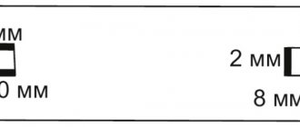
The parting cutter is installed first. Its position along the axis is determined by the base end of the workpiece and, therefore, the distance from the cutter to the end of the steady rest collet (or spindle when processing without a steady rest), which serves as the basis for determining the relative position of the cutters involved in processing along the axis of the workpiece, the distance between the blade of a conventionally shaped cutting tool and the end the steady rest collet should be as small as possible (when processing rods with diameters up to 10 mm - within 0.5-1 mm, and more than 10 mm - within 1-2 mm).
The adjustment of the cutters in the center of the workpiece on the rack supports is carried out by tilting them in a plane perpendicular to the axis of the machine spindle, for which the locking screws are unscrewed and the screws are screwed in, or vice versa. The adjustment of the cutters fixed in the tool holders with screws on the balancer supports is carried out with a screw. A spring pusher ensures that the tool holder is pressed against the screw stop, and a cap on the thread provides the required degree of tension for its spring.
The cutters for performing other transitions are adjusted in the order of alternating the latter. Along the axis of the workpiece being processed, the cutters are installed in such a way that the distances from the end of the steady rest collet (or the end of the spindle when processing without a steady rest) to their blades, which will form certain surfaces of the workpiece, determining the shape of the product and its longitudinal dimensions, are equal.
Longitudinal adjustment of the strut calipers is carried out by moving their bodies with screws along the limb and locking them with screws. The balancer supports are adjusted with screws along the dials.
When checking the alternation of processing transitions, the following is identified: interference with the unhindered movement of tools and their causes; timely start and end of working and idle strokes of each tool; correctness of processing modes in transitions during combined operation of tools (especially depth of cut t for cutters and feed for drills) by pressing the workpiece. The test is carried out by turning on the mechanical rotation of the machine spindle with manual rotation of the camshaft. Turning on the electric motor is preceded by a control check of the reliability of fastening the tool in the tool holders and chucks of the tool spindles.
Rice. 5. Balancer with supports of a longitudinal turning machine: 1, 3—6, 9, 11, 14 — screws. 2 — spring pusher, 7 — tool holders, 8, 13 — limbs, 10 — stop, 12 — cap; a—c—position of the copy finger
The timeliness of the start and end of working and idle strokes of each tool is primarily controlled in transitions with combined movements of the caliper and spindle head when processing shaped or conical surfaces, and then in transitions where the beginning or end of the tool stroke is associated with obtaining a given product size.
The correctness of processing modes during combined tool operation is determined by obtaining the specified dimensions and shapes of product surfaces (for example, in transitions of the same processing scheme). So, in the transition, the incisors work simultaneously. It may turn out that the cutting club assigned for the processing process is large and leads to the workpiece being pressed out, as a result of which the cutter distorts the shape and dimensions of the surface being turned. Incorrect depth of cut may also be a consequence of inaccurate installation of the cutter and support in the initial position and the increased cutting conditions imparted to the drill in the transition.
Dynamic interference is a consequence of the use in machines of cams with incorrectly executed sections of the profile, i.e., incorrect angles in the number of degrees corresponding to each of these sections, and appear at high idle speeds. These interferences are characteristic of processing with short (in time) automatic cycles, i.e. with high productivity, and therefore with a high camshaft rotation speed, and are manifested in separation of the tracer finger from the cam surface, impacts and other phenomena. Dynamic interference can be detected only when the camshaft is subjected to mechanical rotation at a given frequency.
Adjustment of the position of the tools to obtain the specified dimensions and shape of the product is carried out according to the actual results of processing (with a mechanical drive of the camshaft) during sequential transitions. To carry out measurements that determine the actual dimensions, the processing process is interrupted, first turning off the rotation of the camshaft, and then turning off the rotation of the machine spindle. Measuring instruments according to the sensitivity threshold must correspond to changes in the determined dimensions within the limits of their permissible deviations.
When adjusting the balancer cutters, loosen the screw that secures the slider rigidly to the balancer body. By rotating the screw, the slider is moved in the desired direction by half the actual deviation of the diameter of the product from the required size. The displacement value is counted according to the divisions of the dial. Machines mod. 1M06 and 1D25A have double dials. The dial operates when the screw is screwed in all the way (in this case, one division is 0.02 mm of linear movement of the cutter). If finer control is necessary, a dial with a division value of 1 micron is put into operation, for which a screw is screwed in. When the screw rotates, movement occurs simultaneously along two screw pairs with different pitches and directions (right and left) of the thread. Before grooving, the screw is re-fastened to control the adjustment.
Caliper No. 1 for making precise dimensions of products (especially with cutters with wide blades) is adjusted to work on a hard stop. After making adjustments to the dial by manually rotating the camshaft, the balancer cam is placed in contact with the tracer finger at the point of the smallest radius of the profile. In this position, the screw (micrometric) adjustable stop of the balancer is brought into contact with the stop, while creating some tension in order to select possible backlashes in the connection system of the balancer parts; then the stop is locked.
When adjusting to the exact dimensions of a product under conditions of processing sections with different diameters from two cams with one cutter, one size (diameter) of the product (preferably larger) is ensured by fine adjustment along the dial. The final setting to obtain the second diametrical size does not allow the caliper to move along the dial with the transverse adjustment screw, as this will lead to a violation of the first adjusted size. Regulation is carried out by changing the position of the follower finger of the cam, the profile of which specifies the movement of the caliper to obtain a given product size (in this case, it is necessary to take into account the gear ratios of the lever mechanism). Fine movement of the finger is performed with a micrometric screw (on the levers of the strut calipers - with the same screws). In the absence of a dial to control regulation, it is advisable to know the thread pitch of this screw.
Adjusting the stroke length of tools. Errors in the stroke lengths distort the tapers of the conical profiles of the shaped surfaces of products formed by the simultaneous movements of the caliper and the spindle head (the slope angle will be greater if the stroke length of the spindle stock is less than required or the stroke length of the caliper is greater than necessary). Stroke lengths
The parameters are adjusted by making changes to the ratios 11Нсч of the levers of the lever mechanisms (this is not applicable for the balancer support).
Features of setting up a CNC machine mod. LA155F30. The setup operations of this machine can be divided into three stages, in each of which they are carried out in a certain sequence.
I. Preparation of the machine and tools with partial access to the CNC (numerical control device) in manual control mode: 1) setting an emergency limitation of the work area of the spindle head and support; 2) replacing the spindle collet according to the diameter of the bar being processed; 3) changing the guide rod bushing; 4) setting up the loading device; 5) installation of a steady rest or a rotating steady rest; 6) turning on the CNC with test monitoring of its serviceability; 7) installation of the tool in the tool holders of the caliper stand; setting up a three-spindle device.
II. Entering a control program (CP) from the operator's console: 1) entering a control program from its technological record on a form or from a printout; 2) transitional processing of a product sample in manual mode with control of the size and roughness of surfaces and the introduction of appropriate corrections*; 3) frame-by-frame control of the entered CP by indicating data on the indicators of the operator console.
III. Trial processing in automatic mode and making corrections based on its results: 1) trial processing of a small batch of products in continuous Automatic mode; 2) measuring products, identifying deviations from the requirements of the drawing or cases of extreme use of the tolerance zone; 3) introduction of key corrections.
When a malfunction is detected, its code is displayed on the indicator and eight letter address lamps light up. If everything is working properly, the light above the key begins to blink. To start the CNC system, you need to press the “Start” key, and then the “Start” button on the remote control 4 of the machine. The feed and frame number indicators will show zeros. The device is ready for use. It can operate in several modes: from the handwheel; from manual control keys; automatic; entering a processing program; setting the zero point, but at the same time - only in one mode.
Setting an emergency limit on the work area of the spindle headstock is done by rearranging the bar, crossbar and pin located on the front side of the headstock body. The position of the crossbar and the bar, which determine the rearmost position of the spindle headstock, is adjusted as follows: the headstock is manually moved to the rear position until the possibility of its further advancement is eliminated; from this position it is shifted by 2-3 mm in the forward direction, and in this state the actuation of the rear limit switch from the crossbar is ensured.
Rice. 6. Diagram of the positions of the emergency travel limiters of the spindle head of the machine mod. LA155F30: 1 - pin, 2 - bolt, 3 - stop, 4 - bar, 5 - body, 6 - stop
Rice. 7. Layout of the tool mounting bases and the spindle head of the machine mod. LA155F30 when assigning a reference point from zero: a - diagram of the installation of the tool holder relative to the base surfaces, b, c - diagrams of the installation of the tool holder relative to the coordinate system of the machine; 1 - spindle head, 2 - steady bushing, 3 - steady support, 4 - rod
The installation of the cutting tool in the tool holders is carried out along the base surfaces, the position of which is precisely determined relative to the coordinate system of the machine. So, along the Z axis they are made from the front end of the bushing of the fixed rest of the caliper strut (Fig. 3.23, b, c). Dimension e is achieved by adjusting the screws, the supporting ends of which rest on the lateral base surfaces of the cutters. The values of this size can be different, since they depend on the profile of the cutter - the location of the top of its blade as a design point when counting movements along the X and Z axes. Thus, on cutters / and // these points coincide with the lateral base surface B of the cutter rod, and for a threaded cutter III, the design point is further away by the value D. If the uniformity of the location of the design points of the cutter profiles from the reference point is not ensured, each use of cutters with a different profile will require the processing programs to include a zero shift by the appropriate amount, and then its cancellation. The installation of the cutting tool along the X axis is carried out to ensure the exact distance from the Z axis of rotation from the workpiece to the top of the blade (calculation point). For machine mod. LA155F30 its value is (d /2) +2 mm d - the maximum diameter of the processed rod mm), i.e. 16 mm.
Rice. 8. Zero positions of the cutter blades of the machine mod. LA155F30 relative to coordinate planes
Rice. 9. Adaptation for machine gun mod. LA155F30 for installation and adjustment of cutting tools outside the machine:
Installation of the cutting tool in position c corresponding to the counting of movements according to work program 0b is preceded by setting the device to the standard, the purpose of which is to install it by contacting the movable stops 20 and 22 in a position fixed on indicators 1, 4 and 23 with zero marks.
Adjustment of cutting tools can hardly be done in the following sequence: 1) use locks (high-precision position regulators) to move the installation planes of the stops to the non-working position, and, turning the folding stop on the axis fixed in the stand, move it out from under the indicator and fix it on the finger; 2) install the cutter into the tool holder and lightly press it with clamps; 3) install the holder with the cutter on the fixture and the screw (not shown in the figure) in the pin, “sinking” the spring-loaded stop, press it to plane B; 4) release the stop with the lock, use the screw to move the cutter with the stop until the indicator arrow aligns with zero, and then move the stop to the non-working position; 5) place the folding stop under the indicator and lower it onto the cutter blade; 6) using the screw resting on the finger, adjust the zero position of the blade using the indicator, finally secure the tool holder to the stand and remove the folding stop; 7) release the stops, and use the screws to finally adjust the zero position of the cutter blade using the indicators; secure the cutter in the holder completely and remove it from the fixture.
General information
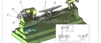
Turret lathes (Fig. 1) are designed for turning parts from rods, various types of forgings and castings, as well as performing other operations with workpieces, such as:
- drilling;
- countersinking;
- boring;
- deployment;
- thread cutting with taps and dies;
- creation of shaped surfaces;
- cutting threads with a cutter.
Figure 1. Turret lathe.
Figure 1. Turret lathe.
The main difference between a turret lathe and other machines of the turning group is the presence of a turret head (Fig. 2). The turret is a device that holds a cutting tool and is capable of changing the working cutter by rotating the drum.
Figure 2. Turret head.
Figure 2. Turret head.
Turret lathes are used in a wide variety of areas with varying production volumes: from small-scale to large-scale. This is due to the fairly wide technological capabilities of this machine. While machines of a more narrow specialization for processing complex workpieces require repeated changes of the cutting tool and even the type of equipment, turret-type machines are capable of performing a wide range of metal-cutting operations in one installation of the part. This allows you to significantly save time and energy costs.
Multi-spindle automatic lathes
And semi-automatic
Automatic and semi-automatic lathes are used in mass and large-scale production for multi-tool processing of workpieces. High productivity is achieved by automation of working and auxiliary strokes, as well as their combination. The layout and design features of automatic and semi-automatic lathes are determined by the level of required productivity, the degree of complexity of the parts being manufactured, and the type and size of the workpieces.
Automatic and semi-automatic lathes can be single- or multi-spindle. Depending on the location of the spindles, they are divided into horizontal and vertical. They also produce shaped cutting machines with a feed movement of the cutters that is transverse relative to the axis of the workpiece; shaped-longitudinal automatic machines with longitudinal and transverse feed movements of the workpiece and cutters, respectively; revolver machines with tools installed in the turret head.
According to their purpose, they are divided into universal and special.
Increasing the productivity of turning is achieved by using multi-spindle (4...12 spindles) automatic and semi-automatic lathes with horizontal and vertical spindles. These machines with horizontal spindles process both piece workpieces (castings, forgings, stampings) and workpieces in the form of rods and pipes.
Processing on multi-spindle machines can be performed using parallel, sequential and rotary schemes. When processing according to a parallel scheme, the same transitions are performed at all positions, and at the end of the working cycle, a number of parts equal to the number of spindles is obtained. When processing according to a sequential scheme, the part processing operation is divided into groups of transitions, which are assigned to processing positions. All spindles with workpieces pass through these positions sequentially. When processing according to a rotary scheme, several workpieces are processed sequentially at positions.
The sequential processing machine is shown in Fig. 22.8. The front 2 and rear 5 racks are installed on the frame 1; forward-
|
A spindle block 3 is mounted on this rack, and a gearbox 6 is mounted in the rear one. Processing is carried out with tools fixed in transverse supports 4, which are installed against each of the spindles in the clamping devices of the axial support carriages 7. Rotation of the spindle block entails moving the workpiece to the next position , where its processing continues with a new set of tools. The penultimate position is the position of final processing and cutting of the finished part from the rod. At the last position, the rod is fed until it stops, and then a new processing cycle is performed.
|
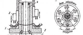
A vertical multi-spindle semi-automatic rotary machining machine is shown in Fig. 22.9. On the frame 1 there is a carousel 2, in which the spindles 3 are mounted. Cortical supports 4 are mounted on the central column 5. The workpiece being processed is clamped in the spindle chuck, from which it receives rotational movementv. The carousel, together with the spindles, makes a slow rotational movement S. At the same speed and the column with calipers rotates in the same direction. When the carousel and column rotate, the workpieces are processed by tools mounted in supports with vertical feed SB. In one revolution of the carousel and column, processing ends.
And semi-automatic
Automatic and semi-automatic lathes are used in mass and large-scale production for multi-tool processing of workpieces. High productivity is achieved by automation of working and auxiliary strokes, as well as their combination. The layout and design features of automatic and semi-automatic lathes are determined by the level of required productivity, the degree of complexity of the parts being manufactured, and the type and size of the workpieces.
Automatic and semi-automatic lathes can be single- or multi-spindle. Depending on the location of the spindles, they are divided into horizontal and vertical. They also produce shaped cutting machines with a feed movement of the cutters that is transverse relative to the axis of the workpiece; shaped-longitudinal automatic machines with longitudinal and transverse feed movements of the workpiece and cutters, respectively; revolver machines with tools installed in the turret head.
According to their purpose, they are divided into universal and special.
Increasing the productivity of turning is achieved by using multi-spindle (4...12 spindles) automatic and semi-automatic lathes with horizontal and vertical spindles. These machines with horizontal spindles process both piece workpieces (castings, forgings, stampings) and workpieces in the form of rods and pipes.
Processing on multi-spindle machines can be performed using parallel, sequential and rotary schemes. When processing according to a parallel scheme, the same transitions are performed at all positions, and at the end of the working cycle, a number of parts equal to the number of spindles is obtained. When processing according to a sequential scheme, the part processing operation is divided into groups of transitions, which are assigned to processing positions. All spindles with workpieces pass through these positions sequentially. When processing according to a rotary scheme, several workpieces are processed sequentially at positions.
The sequential processing machine is shown in Fig. 22.8. The front 2 and rear 5 racks are installed on the frame 1; forward-
| sequential processing |
A spindle block 3 is mounted on this rack, and a gearbox 6 is mounted in the rear one. Processing is carried out with tools fixed in transverse supports 4, which are installed against each of the spindles in the clamping devices of the axial support carriages 7. Rotation of the spindle block entails moving the workpiece to the next position , where its processing continues with a new set of tools. The penultimate position is the position of final processing and cutting of the finished part from the rod. At the last position, the rod is fed until it stops, and then a new processing cycle is performed.
| rotary machining |
A vertical multi-spindle semi-automatic rotary machining machine is shown in Fig. 22.9. On the frame 1 there is a carousel 2, in which the spindles 3 are mounted. Cortical supports 4 are mounted on the central column 5. The workpiece being processed is clamped in the spindle chuck, from which it receives rotational movementv. The carousel, together with the spindles, makes a slow rotational movement S. At the same speed and the column with calipers rotates in the same direction. When the carousel and column rotate, the workpieces are processed by tools mounted in supports with vertical feed SB. In one revolution of the carousel and column, processing ends.
Design and operating principle
In the general case, a turret lathe (Fig. 3) consists of a frame (1) on which the main components are fixed. The gearbox (2) is used to change the rotation speed of the spindle or the clamping and bar feeding mechanism (3). Whether a machine is equipped with a spindle or a bar feed mechanism depends on the specifics of its operation. If a metal rod is used as a raw material for processing, the machine is equipped with a feed mechanism. If the workpiece is a forging or casting, then a standard spindle for this group of metal-cutting machines is installed.
To change the speed of advance of the rod to the turret support (7), there is a feed box (4). To expand the technological capabilities, turret lathes are often equipped with additional devices. The machine presented as a sample for consideration has an additional thread-cutting (5) and copying (6) device. The thread-cutting device is used to create threads according to specified parameters. The copying device is designed to create a surface on the workpiece according to the sample. The turret head is controlled by an apron (8) and a stop drum (9).
There is a pumping station (10), which creates pressure for the operation of hydraulic drives. In the cooling device (11), the temperature of the working fluid decreases. The gearbox (13) serves to reduce the operating speeds of the machine. The drum stop (12) cuts off the feed at the right time. The stand (14) is necessary to support the rod being fed into the work.
Figure 3. Turret lathe for working with rods.
Figure 3. Turret lathe for working with rods.
Recently, despite the high cost, modified turret lathes with advanced technological capabilities and numerical control have been in increasing demand. Such machines have high productivity and precision in manufacturing parts. Here the operator’s work comes down to loading the bar as needed, monitoring the operation of the machine and accepting finished products.
Place an order for turning in St. Petersburg
To place an order with our company, leave a request on the order page of the website , or call us by phone. Our company manager will help resolve all issues related to the order.
Cost of CNC turning work
The final price of work on automatic lathes depends on the specific order. In this case, the determining criterion is the size of the ordered batch - the larger the order, the cheaper the part in terms of the order unit.
An example of calculating the price of manufacturing a product on an automatic lathe
Part name - axle
Material - 20 calibrated steel
Workpiece diameter - 6mm
Lot – 2000pcs
Coating - Ts9
Price — 87 rub/piece
Attention! This cost calculation is not a public offer and your part does not necessarily have the same price. Many factors influence pricing - the number of parts in a batch, the complexity of the part, the material, including whether it is a new customer or a customer who has earned significant discounts.
Regulatory and technical documentation
Steel turning:
GOST 380-94. Carbon steel of ordinary quality (grade). GOST 2590-88. Hot-rolled round steel (assortment). GOST 2879-88. Hot-rolled hexagonal steel GOST 10704-91. Electric-welded straight-seam steel pipes (range) GOST 10705-80. Electric-welded steel pipes (technical conditions). GOST 11068-81. Electric-welded pipes made of corrosion-resistant steel (technical conditions) GOST 8733-74. Cold-deformed and heat-deformed seamless steel pipes (technical requirements). GOST 8734-75. Cold-deformed seamless steel pipes (assortment). GOST 9940-81. Seamless hot-deformed pipes made of corrosion-resistant steel (technical conditions). GOST 9941-81. Seamless cold- and heat-deformed pipes made of corrosion-resistant steel (technical conditions). GOST 7417-75. Calibrated round steel (assortment). GOST 8560-78. Calibrated hexagonal rolled products (assortment). GOST 1050-88. Long-rolled products, calibrated with special surface finishing from high-quality carbon structural steel (technical conditions).
Turning of stainless steels GOST 4543-71. Rolled alloy structural steel (technical conditions). GOST 5632-72. High-alloy steels and corrosion-resistant, heat-resistant and heat-resistant alloys (grades).
A complete list of technical documentation with the ability to download here
Layout of machine 1B265
The basic parts of the machine: bed, traverse, gearbox housing and spindle block housing form a rigid frame (portal).
The machine's workspace is located inside the portal. Calipers and various devices necessary for processing parts are installed there. A screw conveyor is installed at the bottom of the working space to remove chips.
The main camshaft of the machine is located in the upper part of the machine in the traverse. Its lower sections, located directly at the supports, are mounted on the left side of the machine in the spindle block housing. There is also a spindle drum and all the mechanisms associated with it: lifting and turning, drum fixation, rod feeding and clamping, material stop.
The main axis of the spindle drum passes through the working space and is the guide of the central longitudinal support. All drive mechanisms: main drive, camshaft drive, tool spindle drive are mounted on the right side of the machine - the gearbox.
The main electric motor is installed in the frame, at the rear of the machine, the bar material is supported by guide pipes with a stand.
Design and operational features of the 1B265 machine
Design and operational features of the machine:
- Installation of the working stroke of the longitudinal support and independent devices is carried out without changing the fists
- For standard machines, the working stroke of the transverse supports is set using a standard set of 8 knuckles, common to all supports. The simplicity of changing the angle of the machine's working stroke by rearranging the corresponding cam of the command device makes it possible in some cases, without changing the cams of the transverse supports, to process various parts of the same type (group adjustment);
- Each of the transverse calipers has an independent drive located in close proximity to the caliper, which ensures high drive rigidity
- The transverse supports are made of a table type with rectangular guides to increase the rigidity and, accordingly, the accuracy of the machine
- There is an electromechanical drive for adjustment operations
- Increased machine precision
Main drive of the machine 1B265-6
From the main electric motor (n = 1460 rpm) through a V-belt drive, the drive shaft I of the machine receives rotation, from which shaft II rotates through gears 4 and 7, connected by replaceable gears a:b. c:d with shaft III to IV - the central shaft of the machine.
The central shaft passes from the gearbox into the spindle block; on its left side sits a gear wheel 41, which meshes with the gears 42 of the spindles.
Machine feed drive 1B265-6
The power stroke drive (feed) is carried out from the central shaft through a worm pair 12, 13, two pairs of replaceable gears e:f, g:b and one constant pair 10, 11 per cup of the electromagnetic power stroke clutch. When the electromagnetic clutch is turned on, rotation is transmitted through a bevel pair 9, 8 to the vertical shaft, then through a gear transmission 19, 16 to the worm shaft 17, which meshes with the worm gear 18 of the camshaft.
In this way, the camshaft located at the top of the machine rotates.
The two lower sections of the camshaft, which impart movement to the lower and middle transverse calipers located in close proximity to them, are connected to the upper camshaft by gears and rotate synchronously with it.
The camshaft also receives rapid rotation from vertical shaft IX, but in this case the latter is driven directly from shaft I through gears 5.6 and an electromagnetic idle clutch on shaft I.
In addition to the automatic camshaft drive discussed above, the latter can be rotated by a setup engine or manually during machine setup. The feed and adjustment drive are switched on using buttons on the control panels.
Adjustment drive . From the flange electric motor, through gears 23, 21 and 20, rotation is transmitted to shaft IX, and from it to the camshaft of the machine. In this case, the electromagnetic clutch on axis XII must be turned off, and on shaft IX must be turned on. The working and rapid speed clutches are turned off, and when the adjustment drive is turned off, the clutch on the XII axis is turned on and brakes the camshaft in the same way as when the feed is turned off. When the setting drive is turned on, the camshaft receives a slow rotation (about 3 rpm), which is used when setting up the machine.
Manual rotation of the camshaft can be carried out by rotating the square on the worm shaft 17.
The input circuit breaker on the electrical cabinet must be turned off.
Drive of tool spindles . During fast drilling, the drive sleeve of the tool spindle receives rotation from the central shaft IV through gears 26, 29 and the replaceable gear “m”. The tool spindle rotates in the opposite direction to the work spindle, thanks to the idler gear.
The rotation speed is adjusted using the interchangeable gear “m”.
For cutting a right-hand thread (or making up a left-hand thread), the movement is transmitted from the central shaft IV, through replaceable gears “i” and “r” to shaft XVI. From it, with the electromagnetic clutch turned on, through gears 27, 24; 25, 28 receives rotation of the tool spindle drive sleeve.
When screwing the tool (or cutting a left-hand thread), the electromagnetic coupling of the shaft ХVI is turned off and the coupling of the shaft XI is turned on. Then the rotation from the central shaft IV to the drive sleeve of the tool spindle is transmitted through the interchangeable gears “i”; "r"; "k"; “l”, then through gears 15, 14; 27, 24; 25.28.
Reaming can be carried out using a quick drilling chain. In this case, another idler gear is installed to ensure the desired direction of rotation of the tool spindle. When used for reaming a thread tapping drive. The replacement gears “k” and “L” are not installed, and the shaft coupling XVI is always engaged.
Auxiliary drives . The screw conveyor is driven by a separate electric motor through a worm pair 30 and 31.
The cooling pumps are driven by their own electric motor, mounted in the same P-180 unit.