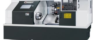
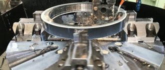
Using a lathe of one of the modern models, you can perform a fairly large list of technological operations for metal processing. But mainly such equipment is used to process the external and internal surfaces of workpieces having a cylindrical, conical and shaped configuration.
Modern lathe
History of the origin and further development of equipment
If you look at modern models, you may get the impression that the lathe was invented relatively recently.
However, information about the most distant ancestor of the modern machine tool dates back to Ancient Egypt of the 2nd millennium BC. Turning technologies were also used in ancient China and India in the 1st millennium AD.
In the 14th century, a foot drive was invented; in the 18th century, the Russian scientist Andrei Nartov invented a screw-cutting lathe with a mechanized support and replaceable gears.
A particularly rapid period of development occurred during the industrial revolution of the late 19th century - the machine changed its drive sources, became increasingly larger, and became more complex.
Now its main source of energy is electricity. The most modern version of the machine appeared in the 1950s, when computer numerical control (CNC) and servomechanisms began to be used to control processing.
The lathe is often called the “mother of all machines” because with its help other machines were first created.
Principle of operation
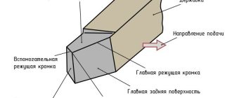
Machining is carried out when the cutter comes into contact with a rotating workpiece. The rotational movement is carried out by a spindle or faceplate; the necessary force and frequency are provided by an electric motor through a belt drive and gearbox. The cutter is mounted in a support and can move in the transverse and longitudinal direction. The feed amplitude depends on the speed of movement of the caliper.
Machines can be with a vertical or horizontal layout. This depends on the position of the spindle on which the workpiece is mounted. The vertical layout is optimal for processing heavy and short parts, the horizontal - for long ones with a small or medium diameter.
Main advantages of turning:
- High complexity of manufactured parts.
- Ability to work with any metals.
- High quality and precision processing.
- Great performance.
Types and varieties of turning equipment
There is a division of machines according to the following criteria:
- The largest permissible size of the workpiece being processed above the bed.
- RMC – distance between centers (small – up to 150 mm, medium – 150–300 mm, large – more than 300 mm).
There are also many types of lathes, each with its own specific characteristics:
Screw-cutting lathes
Lathes are very common due to their versatility. The principle of operation is simple: an object clamped on a spindle in a horizontal position is given rotation, and cutting occurs with the help of a movable cutter. The cutter can be either fixed or separate.
CNC lathes
Automated machines controlled by CNC. The numerical control system ensures high accuracy and serial processing. Operator participation is minimal: creating a control program and monitoring its execution.
Main types of equipment
The classification of lathes is mainly carried out on the basis of their design.
Lathe-screw-cutting
All types of lathes from this group are universal, so they are widely used in serial and individual production.
With their help, you can perform various operations - cutting threads (modular, metric, inch), all kinds of processing of metal workpieces.
The list of main structural elements of this machine includes:
- spindle head. Consists of a spindle and gearbox;
- caliper Designed to fix the cutting tool in the desired position;
- bed. Designed to secure the main structural components of the unit;
- gearbox. Designed to transmit movement from the spindle assembly to the support. This is possible due to the presence of a lead screw or roller in the design;
- apron. Necessary for transforming the movements of the roller or screw to move the caliper in the desired direction;
- tailstock. Often equipped with additional tools to support the workpiece being processed in the desired position.
Machine spindle head
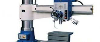
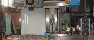
Lathe-rotary
All types of lathes that can be classified as a rotary machine are usually designed for working with large workpieces. They have the following functional abilities:
- used for turning cylindrical or conical surfaces;
- used for cutting grooves of various configurations;
- if necessary, grinding, milling and trimming of ends is performed;
- There is a possibility of carving.
This machine includes a table on which the faceplate is located. There are also racks where the traverse, equipped with calipers, moves.
Lobototurn
The main purpose of a lathe is the processing of cylindrical, conical and frontal parts. In equipment of this type, the axis of rotation of the workpiece is placed horizontally.
Turning and turret
All types of lathes that can be classified as a turret group are designed for processing parts made from calibrated rods. This equipment is capable of performing a wide range of technological operations:
- turning and boring;
- countersinking;
- drilling;
- shaped turning;
- thread forming;
- deployment.
The specific name of the machine is due to the special way of fastening all the tools. They are installed in a special holder - static or driven. The latter type provides the unit with a wide range of capabilities. It can be used for drilling, milling, and thread cutting.
Automatic turning and turret
Turning and milling machining center
This equipment combines the functional capabilities of a milling and lathe. Its structural elements include a cone-shaped milling head, which ensures the performance of many operations, and is therefore capable of worthy competition with the revolving type. In this case, turning is performed using metal-cutting cutters. They are installed in the milling head, which increases their functionality.
Automatic longitudinal turning
The purpose of the longitudinal turning machine is to produce small parts in mass production from various rods, shaped profiles and wire, which is rolled into a coil.
It is used for processing workpieces made of copper, alloy steel and many other metals. Automatic longitudinal turning machines are equipped with the following types of spindle heads - fixed and movable. Also, these units can be turret or single-spindle. The former have some advantages, since they are able to simultaneously perform several operations.
Multi-spindle lathes
Such machines are designed for processing complex workpieces, which are formed from cold-drawn rods of different sections or from pipes. They are mainly used to meet the needs of mass production. With their help, the following operations are carried out:
- turning, boring and trimming;
- drilling;
- deployment;
- thread formation;
- countersinking.
The high performance of such an automatic machine is ensured by the high power of the drive mechanism, sufficient rigidity of the structure, and the ability to simultaneously perform several operations.
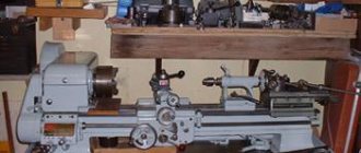
Tabletop
The main distinguishing feature of this machine is that it is fixed on a special table. This type of units has small dimensions and weight.
With its help, you can perform a wide range of various technological operations for processing parts made of metal, wood, and plastic. Also, desktop-type units are capable of drilling, boring or milling.
Basically, such equipment is used at home or to meet the needs of small-scale production. Its advantage is considered to be low energy consumption and low cost. During operation of tabletop machines, the noise is minimal, which is greatly appreciated by many users.
CNC machines
Many machines of different designs are equipped with computer numerical control or CNC. They are characterized by high productivity, accuracy and ease of operation.
When implementing CNC, the following types of systems are mainly used:
- open. They imply the use of one stream of information. Such a unit first decrypts the data, only then transmits the given commands to all mechanisms;
- closed. This system works using two streams of information, which are received from the reading and measuring mechanism;
- self-adjusting. All information is corrected based on changes that occur during processing of parts.
Also, CNC machines are divided into types depending on how the main work processes are managed:
- positional. They involve installing a mechanism for processing parts in the desired position, only after which the work process itself begins;
- rectangular. These systems are used for processing workpieces that have a stepped shape. They are capable of automatically switching longitudinal and transverse gears;
- contour. Ensure continuous operation of the unit in accordance with the specified parameters.
Machines with continuously variable drive
The continuously variable drive provides turning equipment with the ability to continuously change the spindle speed.
Using this unit, you can process the internal and external surfaces of workpieces. At the same time, the entire work process occurs in the presence of the best speed parameters. Also, machines with stepless drives are characterized by a long service life, ease of operation and reliability. This is partly ensured by the absence of a gearbox. The spindle speed is adjusted mechanically, electrically and hydraulically.
Pipe cutting units
These lathes are highly specialized. They are used only for cutting pipes made of steel. They can also process their ends and apply threads with the required characteristics. These units are widely used in various industries, including oil and gas production, geological exploration.
If the pipe cutting machine is equipped with a CNC, it works according to the following scheme:
- the workpiece in the form of a pipe is fixed at both ends in the chuck;
- a program is installed that can automatically eliminate all defective parts of the part;
- To perform additional operations, the machine is equipped with a turret head, cartridges of various types, and a cutter.
To ensure a long service life of such equipment, its guide elements are hardened and ground. This also improves the accuracy of the unit, which is very important for efficient operation.
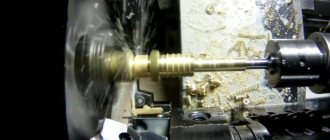
Work performed on turning equipment
There are the following main types of work performed on turning equipment:
- processing of cylindrical surfaces;
- processing of conical parts such as shaft;
- design of complex surfaces of bodies of revolution, shaped turning, turning fillets and roundings;
- trimming of workpieces, processing of ledges;
- turning grooves (external and internal);
- drilling, boring, reaming, countersinking holes; cutting internal and external threads using cutters and other tools - taps, threading heads;
- cutting of workpieces.
Design features of lathe group machines
All machines designed for turning workpieces made of metal and other materials have standard structural elements in their design:
- bed - the supporting element of the turning unit on which all the elements of its structure are installed;
- apron (in this element of the lathe, the movement of the roller or lead screw is converted into the movement of its support);
- spindle headstock, on which the spindle of the device is located, and in its inner part there is a gearbox;
- caliper (in this element of the machine the cutting tool is fixed, the caliper is also needed in order to ensure longitudinal and transverse feed of the tool, carried out with the specified parameters; the design of the caliper must include a lower carriage, and some models have several of them, on the top of which a holder is attached for turning tools);
- feed box (using this structural element, movement is transmitted from the lead screw or roller to the machine support);
- the electrical part of the machine structure, which includes a drive electric motor, the power of which can vary significantly between different machine models, as well as elements that control the electrical equipment of the device (naturally, this part of the turning unit must meet safety requirements).
Main components of a lathe
All structural elements of the machine rest on two pedestals, which perform a load-bearing function and also ensure that the workpiece is placed at a height convenient for the operator. Such cabinets, distinguished by their massive design, can be seen in the photo of a lathe of any model.
The main part of the structural elements of turning equipment is unified, which makes it possible to quickly and cost-effectively carry out their maintenance and repair.
Lathe support design
Machine drive shafts
Example of lathe control layout (click to enlarge)
Machine markings
Machine tools are characterized by the use of numbers and letters equally. The first digit is to designate a group of machines. The third and fourth are to indicate one of the important characteristics. For example, the height of the centers above the bed, or diameters. If there is a letter after the first digit, it means that the model has been improved compared to the previous version. In some cases, serial numbers are used.
Diagram of a lathe with all the main devices
After the verbal description, let's look at the actual drawing of the product:
In the image we see a universal device, which is equipped with the ability not only to perform turning, but also to cut threads.
Here is another schematic photograph of a real unit:
On it we see, in addition to the main and secondary components:
- ● Front and rear cabinets. This is the element of the frame that bears the main load. When designing, the surface area is also taken into account. Their second task is to provide sufficient height for comfortable work of the turner.
- ● On the apron there is a wheel and a handle for moving the longitudinal and transverse slides.
- ● There are also screws for fixing on the tailstock.
- ● In the middle we see a movable block, which is equipped with a handle for attaching the tool holder and a tightening head - this is where the tool is installed.
How does a lathe work and what does it consist of?
The design of all installations includes the following components:
- ● Bed. This is a metal base that supports the entire weight of the remaining elements, as well as the workpiece. All other parts are also attached to it.
- ● Apron. Responsible for converting energy into movement.
- ● Grandmas. There are two of them - one is simply responsible for fixing, the other includes a motor and a spindle that holds and simultaneously rotates the workpiece.
- ● Support. He is responsible for the tool - its movement and fixation.
- ● Feed box and other elements that allow you to change the speed and direction of movement of moving units.
- ● Numerical control panel, which, in turn, includes a display, a cabinet with buttons and the program itself.
These are the main parts, but there are also additional systems, for example, the supply of lubricating and cooling fluid or the removal of chips.
How to install and configure a lathe
First you need to choose a suitable location. This should be the first floor (or reinforced ceilings should be used in advance). The floor can be earthen or concrete. The room itself must have:
- ● good ventilation;
- ● bright lighting;
- ● fire safety measures.
When working with large-sized elements, the workplace should be equipped with a lifting mechanism, as well as a driveway - rails are often installed. For small parts, it is necessary to equip a separate cabinet to accommodate them. You will also need an area for tools.
The thickness and type of foundation depends on the weight of the equipment. The base can be local (pouring a small layer of concrete directly under the frame) or general, when ties and bolts are required.
Setting up the unit must be carried out by specialists. Without confidence in the performance and safety of the product, switching on is not recommended. not only deals with the sale of professional equipment for metalworking, but also configures all important systems.
This image shows the installation of the unit on a concrete floor:
What accuracy classes exist and how do they differ?
The accuracy class is a generalized characteristic of measuring instruments, which is determined by the limit of errors (main and additional), as well as a number of properties that influence the accuracy of measurements made with their help.
The error limit is the greatest error of the measuring device at which it is suitable for measurement. The limit of permissible basic error is expressed in the form:
- absolute;
- relative;
- given
Errors. The class characterizes the property of accuracy of measurements using this device. And the accuracy of measuring instruments is the quality of a measuring device, which indicates that the error of the measurements is close to zero.
If we are talking about the class of accuracy that is provided, for example, by a lathe, then here we mean the class of surface finish of the part that this equipment is capable of providing during the processing of the workpiece.
Measuring instruments, as well as processing equipment, have the following accuracy classes: 0.01; 0.015; 0.02; 0.025; 0.04; 0.05; 0.1; 0.15; 0.2; 0.25; 0.4; 0.5; 0.6; 1.0; 1.5; 2.0; 2.5; 4.0; 5.0; 6.0. In addition, there are several categories of accuracy classes:
Special
This “Class C” is the highest class of equipment accuracy (both measuring and processing). This class includes machines (in our case, lathes) that must process workpieces to obtain the highest class of surface finish (0.01-0.015).
High
For example, jewelry, medical and laboratory scales have a high level of accuracy. Another name for such equipment is precision. It is marked “class B”. If we are talking about turning equipment, then a high class of cleanliness (0.02-0.025) is provided by polishing lathes.
Normal
The normal accuracy class (the marking is “class H”, but as a rule it is not placed) means such a characteristic of equipment or a part that ensures identical results in no less than 98% of obviously identical objects. The absolute indicator of the normal cleanliness class is in the range (2.0-0.6).
Particularly high
Equipment of a particularly high accuracy class is marked “Class A” for this indicator. When designing high-precision equipment, increased attention is paid to the quality of spindle bearings.
Here, rolling bearings are mainly used, also of high accuracy classes, and sliding bearings are made in the form of adjustable tapered bushings. (All standards here are established by GOST 1969-43).
Increased
This accuracy class is marked “class P”. The use of elements of a higher accuracy class (primarily bearings) increases the cost of the finished product processed on such turning equipment.
However, if it is necessary to obtain a higher class of workpiece processing, then elements of a higher accuracy class are used for positioning machine shafts, where higher accuracy and rotation speed are required.
Operating a lathe: how to turn on the device and start working
First you need to install the workpiece in two spindles and check the reliability of the fastening. If one of the holders flies out of its place at high speed, serious consequences are possible, both for the equipment and for the engineer. The second stage is the selection and installation of the tool. For classic tasks, cutters are used; sometimes drills or taps may be needed (when drilling holes and applying internal threads). In CNC-equipped equipment, both of these operations are often performed automatically. On semi-automatic machines this is done by the operator.
Further actions may vary depending on the type of machine.
On automatic:
- ● Develop a project, enter data into the control system.
- ● Turn on the lathe.
- ● Monitor the correct execution of the procedure.
For manual production:
- ● Turn on the engine.
- ● Using the gearbox, select the optimal number of rotations per second.
- ● Use the handles and wheel to control the movement of the caliper, cutting off the desired size of the top layer.
Also, control measurements should be carried out at different stages. Then you can sand it.
Classification of lathes by degree of automation
The degree of automation is the ratio of the time of automatic transitions to the total processing time of the product on the machine.
The capabilities and classification of modern lathes by degree of automation are given in table. 1.12.3.
1.12.3. Classification of lathes by degree of automation
- Manual control
- Installation of workpiece and tool, positioning of working parts and formation of basic cycles manually. Automated positioning of working bodies and formation of basic cycles
- Semi-automatic control
- Consistency of manually generated basic cycles. Partial manual modification of basic cycle stages. Free modification of basic cycles with manual tool replacement
- Arbitrary automatic change of basic cycles with tool replacement. Arbitrary automatic change in the order of execution of basic cycles with a corresponding change in the order of operation of the tool. The same, including manipulations with the workpiece and the processed part. Fully automatic organization of the part manufacturing cycle