Beam deflection calculations must be carried out for almost any structure to check its reliability and strength. Under the influence of external and internal factors and natural phenomena, the beam is subject to deformation.
The beam is compared to a rod fixed to supports. The more supports, the more difficult it is to carry out the calculation yourself. The main load is calculated by adding forces perpendicular to the section.
This calculation is the basis of strength resistance and helps determine the highest deformation. The indicator values must be within the acceptable range.
Types of beams
When constructing buildings, beams of different configurations, sizes, profiles, and cross-sectional nature are used. They are made of metal and wood. For any type of material used, an individual bending calculation is required.
Types of beams:
- Wooden
— they are used mainly in the construction of individual buildings. They are used in the construction of floors, ceilings, and load-bearing floors. Wood is a capricious material and is subject to deformation. To determine the maximum bending, the following parameters are essential: the profile used, size, load, nature of the cross section.
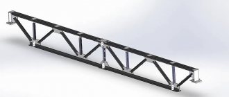
- Metal
— such beams are made from an alloy of metals and their cross-section is complex. Therefore, special attention is paid to the rigidity as well as the strength of the connections. Metal beams are used in the construction of high-rise buildings and structures that require high strength.
Information
The beam plays the role of a fundamental element in the supporting structure.
Its function is equivalent to the core of the entire structure, which is firmly fixed. When constructing any structure, it is very important to carry out a competent calculation of the beam for deflection and eliminate errors in the calculations. First of all, a calculation is required to determine how much the beam is deformed during the operation of the structure. If during the calculation the deformation indicator is within the normal range, then the required parameters of the future beam can be determined (section, material, size, and so on). When calculating the strength of a beam, it is necessary to clearly know the types of material from which the beams are made (steel, wood, concrete, aluminum, glass and copper). Next, you need to pay attention to the fact that the types of loads, as well as their schemes, also differ. For example, a distributed load means that the pressure is not applied to one point, but is distributed over the entire area of the beam. The concentrated type of load characterizes the direction of pressure on one small section (point) of the beam.
Beam strength and rigidity
When designing, you should take into account the bending of the beams so that the structure is reliable, high-quality, durable and practical.
These parameters are influenced by the following factors:
- the magnitude of external loads, their position;
- parameters, character, finding the cross section;
- longitudinal quantities;
- material;
- number of supports, method of their fastening.
There are 2 methods of calculation: simple - a magnifying factor is used, and accurate - additionally includes border calculations.
What is beam deflection?
Under the action of an external load, the cross sections of the beam move vertically (up or down), these movements are called deflections . In addition, the sections are rotated at a certain angle. These two quantities, for any section, can be determined using the initial parameters method.
ν-deflection of section C; θ is the rotation angle of section C.
Calculation of deflections is necessary to perform stiffness calculations. A beam can be considered rigid only if the calculated deflections do not exceed the permissible values. If the rigidity condition is not met, then measures are taken to increase it. For example, they are set by another material, which has a GREATER elastic modulus. Or they change the geometric parameters of the beam, most often the cross section. For example, if an I-profile beam No. 12 is not suitable in terms of rigidity, I-beam No. 14 is accepted and a recalculation is made. If necessary, repeat the selection until they find the right one - the I-beam.
Stiffness calculation
Calculation algorithm:
The formula indicates:
- M – max moment occurring in the beam;
- Wn,min – moment of resistance of the section (tabular indicator);
- Ry – bending resistance (calculated indicator);
- γc – indicator of working conditions (tabular indicator).
Such a calculation is not labor-intensive, but for a more accurate value the following is required:
- working plan of the facility;
- determination of the characteristics of the beam, the nature of the section;
- determination of the maximum load acting on the beam;
- estimation of the maximum deflection point;
- checking the strength of max bending moment.
Initial parameters method
The initial parameters method is a fairly universal and simple method. Using this method, you can write a formula to calculate the deflection and rotation angle of any section of a beam of constant stiffness (with the same cross-section along the length).
The initial parameters are understood as already known movements:
- deflections in supports are zero;
- in a rigid embedment, the deflection and rotation angle of the section are zero.
Taking into account these properties, they are also called boundary conditions, displacements in other parts of the beam are determined.
Calculation of deflection and its features
It is necessary for all floors with high operational loads.
When applying the appropriate coefficients, adhere to the following:
- a beam supported by one rigid and one hinged support, subject to a concentrated load;
- a beam supported on a rigid and hinged support, subject to a distributed load;
- cantilever type load;
- impact of complex load.
Calculation of beam deflections
Let's see how to use the initial parameters method using the example of a simple beam, which is loaded with all kinds of loads, in order to maximally cover all the subtleties of this method:
Support reactions
To make the calculation, you need to know all the external loads acting on the beam, including the reactions occurring in the supports.
If you don’t know how to determine reactions, then I recommend studying this material, where I tell you how they are determined using the example of the same beam:
Coordinate system
Next, we introduce a coordinate system with the origin on the left side of the beam (point A):
Distributed load
The initial parameters method, which we will use a little later, only works when the distributed load reaches the rightmost section, the one farthest from the origin of the coordinate system. Specifically, in our case, the load breaks and such a design scheme is unacceptable for further calculations.
If the load were applied like this:
Then we could immediately begin calculating displacements. We will need to use one tricky trick - introduce additional loads, one of which will continue the existing load q, the other will compensate for this artificial continuation. Thus, we obtain an equivalent design scheme, which can already be used in the calculation using the initial parameters method:
Here, in fact, are all the preparatory steps that need to be done before the calculation.
Let's proceed directly to the calculation of the beam deflection itself. Let's consider the section in the middle of the span - section C:
We write down the boundary conditions relative to the coordinate system. Taking into account the method of securing the beam, we fix that the deflections at points A and B are equal to zero, and the distances from the origin to the supports are important:
\[ { V }_{ A }=0\quad at\quad x=0 \]
\[ { V }_{ B }=0\quad at\quad x=8m \]
We write the equation of the initial parameters method for section C:
\[ E{ I }_{ z }{ V }_{ C }=… \]
The product of the beam stiffness EI and the section deflection C will be the sum of the product EI and the section deflection at the origin of the coordinate system, that is, section A:
\[ E{ I }_{ z }{ V }_{ C }=E{ I }_{ z }{ V }_{ A }+ … \]
Let me remind you that E is the modulus of elasticity of the first kind, depending on the material from which the beam is made, I is the moment of inertia, which depends on the shape and dimensions of the cross section of the beam. The angle of rotation of the cross section at the origin of the coordinate system is also taken into account, and the angle of rotation is additionally multiplied by the distance from the section in question to the origin of coordinates:
\[ E{ I }_{ z }{ V }_{C }=E{ I }_{ z }{ V }_{ A }+E{ I }_{ z }{ \theta }_{ A } \cdot 4+… \]
Accounting for external load
And finally, you need to take into account the external load, but only that which is located to the left of the section C under consideration. There are several features here:
- Concentrated forces and distributed loads that are directed upward, that is, coincide with the direction of the y-axis, are written in the equation with a plus sign. If they are directed downward, respectively, with a minus sign:
- Moments directed clockwise are positive, counterclockwise are negative:
- All concentrated moments need to be multiplied by the fraction:
\[ M\cdot \frac { { x }^{ 2 } }{ 2 } \]
- All concentrated forces need to be multiplied by the fraction:
\[ F\cdot \frac { { x }^{ 3 } }{ 6 } \]
- The beginning and end of distributed loads must be multiplied by a fraction:
\[ q\cdot \frac { { x }^{ 4 } }{ 24 } \]
Where did these numbers and degrees come from? All these things follow when integrating the differential equation of the elastic line of a beam; in the method of initial parameters, all these conclusions are omitted, that is, it is, as it were, a simplified and universal method.
Deflection formulas
Taking into account all the rules described above, we write the final equation for section C:
\[ E{ I }_{ z }{ V }_{ C }=E{ I }_{ z }{ V }_{ A }+E{ I }_{ z }{ \theta }_{ A } \cdot 4+\frac { { R }_{ A }\cdot { 4 }^{ 3 } }{ 6 } -\frac { F\cdot { 4 }^{ 3 } }{ 6 } -\frac { q \cdot { 2 }^{ 4 } }{ 24 } \]
This equation contains 2 unknown quantities - the desired deflection of the section C and the angle of rotation of the section A.
Therefore, in order to find the deflection, we will compose a second equation for section B, from which we can determine the angle of rotation of section A. At the same time, we will fix the material passed through:
\[ E{ I }_{ z }{ V }_{ B }=E{ I }_{ z }{ V }_{ A }+E{ I }_{ z }{ \theta }_{ A } \cdot 8+\frac { { R }_{ A }\cdot { 8 }^{ 3 } }{ 6 } -\frac { F\cdot { 8 }^{ 3 } }{ 6 } -\frac { q \cdot 6^{ 4 } }{ 24 } +\frac { q\cdot 2^{ 4 } }{ 24 } =0 \]
Let's simplify the equation:
\[ E{ I }_{ z }{ \theta }_{ A }\cdot 8+874.67=0 \]
Expressing the angle of rotation:
\[ { \theta }_{ A }=-\frac { 874.67 }{ 8E{ I }_{ z } } =-\frac { 109.33 kN{ m }^{ 2 } }{ E{ I }_{ z } } \]
We substitute this value into our first equation and find the desired displacement:
\[ E{ I }_{ z }{ V }_{ C }=\frac { -109.33\cdot 4E{ I }_{ z } }{ E{ I }_{ z } } +\frac { { R }_{ A }\cdot { 4 }^{ 3 } }{ 6 } -\frac { F\cdot { 4 }^{ 3 } }{ 6 } -\frac { q\cdot { 2 }^{ 4 } }{ 24 } =-\frac { 280kN{ m }^{ 3 } }{ E{ I }_{ z } } \]
Calculator
| Calculation example |
Related calculators:
- Collection of loads on floor beams online
- Calculation of a rectangular pipe
- Square pipe calculation
- Channel calculation
- Angle calculation
- Calculation of a wooden beam
- Calculation of I-beam stability.
Instructions for the calculator
Initial data
Terms of Use:
Span length (L) is the distance between the two inner edges of the walls. In other words, the span that the calculated beams cover.
Beam pitch (P) is the step along the center of the beams through which they are laid.
Type of ceiling - if you will not live on the top floor, and it will not be heavily cluttered with things dear to your heart, then select “Attic”, in other cases - “Interfloor”.
Wall length (X) - the length of the wall on which the beams rest.
Beam characteristics:
Beam length (A) is the largest dimension of the beam.
Weight 1 lm . — this parameter is used as if in the second stage (after you have already selected the desired beam).
Design resistance Ry - this parameter depends on the steel grade. For example, if the steel grade is:
- C235 - Ry = 230 MPa;
- C255 - Ry = 250 MPa;
- C345 - Ry = 335 MPa;
But usually Ry = 210 MPa is used in the calculation in order to protect oneself from various kinds of “force majeure” situations. After all, we live in Russia - they will bring rolled metal from the wrong grade of steel and that’s it...
Elastic modulus E - this parameter depends on the type of metal. For the most common ones, its value is:
- steel - E = 200,000 MPa;
- aluminum - E = 70,000 MPa.
Load:
The values of standard and design loads are indicated after they are collected on the floor.
Price per 1 ton - the cost of 1 ton of rolled metal.