Publication date:
08 Feb 2022
Author:
Alexander Zabolotny
- Calculation of beams for bending
- Strength and rigidity of a beam in bending and construction of diagrams of bending moments and shear forces
- Bending problems with solutions and plotting
- Sequence of calculation of beams for bending
- Method of sections for constructing diagrams of bending moments and shear forces.
We will consider such questions today on this page. Here is a video lesson on this topic and a description of it. So, let's go!
Load more
Here are some other lessons on strength of materials you will find on my website:
Load more
Hypotheses and definitions for bending
First of all, let's start with the definitions and hypotheses that we introduce in the strength of materials when studying bending:
What is a beam? A beam is a rod whose length is significantly greater than its width and height. At the same time, it experiences bending deformation.
beam - called a structural element when the length is significantly greater than the width and height
Bend , what is it? This is a type of deformation in which the longitudinal axis of the beam is bent, but the longitudinal fibers do not press on each other, and the sections are flat before bending and remain so after bending.
bending sign rule
The figure above shows a diagram for deriving the stress formula and a demonstration of the stresses that arise during pure bending. This term will have to be explained in another article. In the meantime, let's continue.
A diagram is a graph of changes in the quantity for which it is constructed. So the bending moment diagram is a graph of the change in internal force - bending moment along the length of the beam. Using this graph, plotted to scale, you can use simple operations to determine the value of the bending moment at any point along the length of the beam. Diagram of shear force - similarly, a graph of its change in internal force - shear force along the length of the beam.
Review[edit]
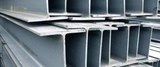
Typical section of I-beams.
There are two standard forms of I-beam:
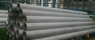
- I-beam products produced by hot rolling, cold rolling or extrusion (depending on the material).
- A plate beam, formed by welding (or sometimes bolting or riveting) plates.
I-beams are typically made from structural steel, but can also be made from aluminum or other materials. A common type of I beam is the rolled steel beam
(RSJ), sometimes incorrectly displayed as a
reinforced steel beam
. British and European standards also specify universal beams (UB) and universal columns (UC). These sections have parallel flanges, unlike the various thickness RSJ flanges which are now rarely rolled in the UK. Parallel flanges are easier to connect and eliminate the need for tapered washers. UCs have equal or nearly equal width and depth and are more suitable in a vertical orientation to carry an axial load, such as columns in a multi-story structure, while UBs are significantly deeper than their width and are more suitable to carry a bending load, such as a beam elements in the floors.
I-beams—I-beams made from wood with fiberboard and/or laminated timber—are also becoming increasingly popular in construction, especially in residential buildings, because they are lighter and less prone to warping than solid wood beams. However, there was some concern about their rapid loss of strength in fire if they were not protected.
Constructing bending diagrams
Let's start constructing bending diagrams.
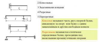
For simplicity, let’s take a beam clamped on one side and the free edge of the beam on the other side (video lesson about types of supports and support reactions). Why is it easier this way? Because with this method of fastening it is not necessary to determine the support reactions. There will be no such need. It will become clear why later.
cantilever beam when calculating bending
The figure shows one longitudinal axis, but the cross section is not shown. What is this axis? This is the axis on which there will be no deformation (neutral layer, above in the figure). For sections that have a simple shape, such as a circle, square, rectangle, I-beam or complex composite shapes, this line always passes through the main central axes (again, for now there’s a video lesson on “moments of inertia”, and later I’ll write an article). To construct diagrams this is enough.
For an example of calculating a beam for bending, we take a cantilever beam
So, we have decided on the calculation scheme, now let’s move on directly to the calculation itself.
Bending section method
Let's show the section on the beam and give some explanations to it:
beam, force on the console and section drawn at distance x
Load more
Usually this diagram is drawn in one color, but to make it easier to describe in the text, I divided it into three colors.
We take the origin of the coordinates of the x axis under the force F. I.e. under this force x =0. It is convenient to take the positive direction of the axis to the left, towards where the rest of the beam is located. Accordingly, x changes from zero to the full length of the beam. Only within these limits does the beam exist.
The section, which is indicated in the diagram “poisonously green”