Connection calculation method
There are several types of metal bonds and for each of them the calculation of the weld is carried out individually. Depending on the location of the parts being welded, connections are divided into:
- angular , when the parts to be welded are located perpendicular to one another. To increase the strength of the structure, it is necessary to correctly determine the maximum forces on the fillet weld;
- butt. Here the ends of the parts are connected, with one part acting as a continuation of the second. This method of coupling is accompanied by minimal stress concentrations and is considered the most rational. Seams can be straight or oblique;
- overlap , in which the elements of the parts slightly overlap one another. As a rule, this technology is used when welding metals whose thickness does not exceed 5 mm, when it is necessary to strengthen the seam;
- T- bars Externally they resemble corner ones. The fastened elements are located at right angles to each other, but are connected at the ends. In the production of metal structures, such joints are used quite often. They are characterized by ease of execution, cost-effectiveness and high strength. For high-quality execution of this type of connection, a manual will be a good assistant; the calculation of a T-weld joint can be performed using it with impeccable accuracy, and possible errors can be avoided.
How is the cross-section of a fillet weld or other types of joints calculated? There are generally accepted formulas that are used to calculate welds at different joints. There is also a special program for calculating welded joints that is freely available on the Internet, using which, by entering the necessary parameters, you can obtain the required result.
Regulations
The main document defining the standards for the design of steel structures are the building codes and regulations (SNiP) SNiP II-23-81, approved by order of the TsNIISK named after. Kucherenko dated November 28, 1983 No. 372/l. In this document, one of the chapters provides rules for calculating welded joints.
However, this document is general in nature and concerns not only welding work, but also other types of joints, so the “reference book” for a professional welder is a manual on the calculation and design of welded joints of steel structures, developed by the same institute. The manual examines theoretical and practical issues of calculating welded joints with fillet welds. Correct calculations can ensure savings in consumables with high levels of strength and reliability.
What parameters are required for calculation
In order to carry out welding calculations with a minimum error, you should know what parameters affect the strength of the joints. To determine the process of compression and tension of a material, the formula should be used:
When calculating, the following indicators will be required:
- Yc is the coefficient of conditions prevailing in the workplace. the parameter is generally accepted, indicated in standardized tables. It simply needs to be inserted into the formula used to calculate the fillet weld;
- Rу is the resistance of the material being welded, taking into account the yield strength. Determined using standard tables;
- Ru is the metal resistance according to the temporary resistance. The values for the substitution in the formula must be looked for in the tables;
- N is the maximum permissible load that the seam can withstand;
- t is the minimum thickness of the material of the elements being welded;
- lw is the longest length of the welded joint; when calculating, it is reduced by 2t;
- Rwу is the resistance determined depending on the tensile strength.
In the case when it is necessary to weld metals of different structures into a single structure, the Ru and Ry indicators are taken based on the material with the lowest strength.
Also, if you need to calculate a weld for shear, then the indicators should be chosen for the material with less strength.
When designing steel structures, the main requirement is to ensure the maximum possible strength of the joint and the immobility of the elements connected by it. According to the requirements and taking into account the location and size of the seams, it is possible to accurately determine their optimal type. If to create a metal structure it is necessary to make several seams at once, then they must be positioned in such a way that the load is evenly distributed on each of them.
Such parameters can be determined through mathematical calculations. If the results obtained are unsatisfactory, then changes must be made to the design and all calculations must be carried out again with new parameters.
General information.
Typically, the Greek letter φ is used to denote the strength coefficient of welded joints. The website uses the letter f for designation in calculations.
The design strength factor φ is a relative value used in formulas to determine the wall thickness of the design part and takes into account weakening by holes and welded joints.
Strength coefficients are determined during the strength calculation process according to the selected calculation method. In different methods, the classification by strength coefficient can be different and have its own nuances.
Features of calculations for products with corner joints
Determination of the pull-off length of the weld is carried out taking into account the force directed towards the center of gravity. The cross section for calculations should be chosen with a high degree of danger.
Calculation of a weld for shear is carried out according to the formula:
Regardless of the type of metal, each of the indicators affects the strength of the joints:
- N is the maximum load that exerts pressure on the joint;
- ßf, ßz - are indicated in the table and do not depend on the steel grade. As a rule, ßz is equal to 1, ßf - 0.7;
- Rwf - shear resistance value. Indicated in GOST tables;
- Rwz - resistance existing at the junction line. The values are standard and taken from the table;
- Ywf - is 0.85 for a joint whose material has a resistance of 4200 kgf/cm²;
- Ywz - for all steel grades is 0.85;
- c is the coefficient of working environment conditions, standard value from the tables;
- kf - indicates the thickness of the seam being created; it should be measured along the fusion line;
- lw - calculated by the total length of the joint, reduced by 10 millimeters.
Values can be calculated based on the connection line or the material being welded. Calculation of fillet welds is performed based on the section.
To understand how to correctly calculate welded joints and structures, examples and problems can be viewed on specialized websites on the Internet.
Calculation of weld leg length
Heavy objects to be welded, such as metal structures and cars, must withstand high loads, so for a quality connection it is extremely important to carry out accurate calculations that will take into account all parameters. One of them is the seam leg (K).
The weld leg is one of the sides of the largest conditional triangle with equal sides that can be inscribed in the cross-section of the joint (GOST R ISO 17659-2009, which came into force on July 1, 2010). This side can be measured based on the dimensions of the elements being welded.
When choosing a side, it is important to consider the size of the workpieces, their position and type of welding. The selection is carried out for each element, but is considered in general terms. It is acceptable to use a template for household measurements.
The connection will be strong if the same sides of the triangle have the same length. Relevant for elements located at an angle of 90°.
Types of connections
:
- butt (without beveled edges, with one-sided, with V-shaped, X-shaped, curved bevel);
- end;
- overlap;
- corner (angle from 30°, one-sided, two-sided without beveled edges, with one or two bevels);
- T-shaped (acute or straight angle, one-sided, two-sided, without beveled edges, with one or two bevels).
It is possible to calculate the length of the weld leg depending on the thickness of the material only for three types of welds: fillet, T-joint and overlap. Such calculations must be carried out when working in the industrial sector. The strength of the joint, wire consumption and its diameter depend on the indicator of these calculations.
be careful
! If the side of the triangle is long, due to the larger heating area, the volume of liquid metal and additive consumption will increase, which means that there is a possibility of product deformation.
When welding parts of different sizes, the leg length is also taken into account. All calculations are based on lower values.
The volume of deposited metal will be equal to the square of the leg. For example, with an increase in K by 1 mm and a welding seam length of 10 mm, wire consumption will increase by 20%. For overlapping materials with a thickness of up to 4 mm, K = 4. If this value is greater, then 40% of the thickness is taken and another 2 mm is added.
Corner welded joints are
:
- normal (without convexity or concavity) – K will be equal to the thickness of the metal;
- concave – K = 0.85;
- convex – K= s × cos45°, where s is the width of the junction, cos45° = 0.7071;
- special (the triangle is not isosceles).
When calculating the length of the weld leg, among other things, the welding method and the fluidity of the material being welded play an important role.
The obtained result must be checked against the requirements of GOST 11534-75 and GOST 5264-80 or reference materials.
At home, for proper welding, you need to install the side of the triangle, which will be 1–1.5 mm thicker than the thickness. You can also determine the indicator using the table.
Remember that K is always less than the thickness of the thinnest part multiplied by 1.2. The length of the weld must be no less than K times 4.
As a rule, all calculations are quite conditional, because in practice they are based on the following premises:
- the load is distributed evenly along the entire length of the deposited filler;
- destruction is possible only through an additive layer equal to 0.7 K.
In fact, the purpose of design calculations is to determine the most suitable weld dimensions for a given value of elongation and axial stress.
The optimal length of the deposited filler based on tensile load can be determined using the following simple formula:
L = F / ρ × [ρ], where:
L
– length of the junction;
F
– planned actual load on the connection;
ρ
– permissible load on the connection.
Optimal length for axial stress
:
L = F / 0.7K × ρ.
From this formula we can derive a formula for calculating K for a deposited filler length of 1 m:
K = 0.7 × L × ρ,
K=0.7 × ρ.
Thus, K will completely depend on the magnitude of the permissible load.
Permissible loads regarding compression, tension and shear for various welding methods can be found in specialized tables and reference books.
Important aspects when developing project documentation
:
- We decide on the choice of method, type of welding and brand of electrode.
- We find the permissible load norm.
- We calculate the length of the weld seam and the axial stress.
- We construct a drawing of the connection of materials.
- We specify the dimensions of the welded elements and technical indicators.
To improve the quality of welding and minimize unnecessary costs when preparing design documentation, it is necessary to determine the exact length of the weld leg from the material and the optimal length of the weld.
Recommended articles
- Types of welds: differences from joints and descriptions of varieties
- How to cook with electric welding: technology and important rules
- Capacitor welding: process features
The main thing is to get strong and high-quality connections at minimal cost.
This indicator plays a decisive role in the production sector of industrial enterprises that manufacture powerful metal structures. During operation, the latter must withstand heavy loads.
The length of the weld seam is one of the most important characteristics that determines the main parameters of the finished product. Any craftsman needs to know how to correctly calculate this indicator so that the work is done efficiently and reliably.
Calculations for overlap joints
The calculation of an overlap weld is carried out taking into account the type and position of the joint, since with this technique the joints can be corner, frontal and flank.
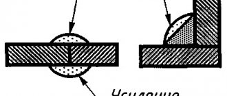
When welding metal parts with an overlap, the strength of the bonding line and the minimum cross-sectional area are determined. The formula for the area of the weld implies the use of a smaller height of the triangle of the conditional joint. With the same dimensions of the legs of this triangle for manual welding, the height is 0.7.
During automatic and semi-automatic welding, the depth of heating of the material is greater, therefore the conventional indicators indicated in the standard tables are taken as the height.
Let's look at examples.
If the welding process was carried out in automatic, semi-automatic or manual mode, then β will be equal to 0.7. This will create a seam in the shape of an isosceles triangle. In the case when the welding process took place in a semi-automatic mode, but there was not one approach, but several (2 or 3), then β will already be equal to 0.8; for the same case, but in automatic mode β=0.9, and for automatic single-pass welding - β=1.1. Required to take K [Total: 2 Average: 3/5]
How to calculate the length of welding joints based on the mass of metal
To determine the length of the connection, there is a formula indicating the ratio of the mass of the weld over the length of one meter of the weld.
The formula is as follows: L = G/F × Y , in which L denotes the length of the weld, G is the weight of the deposited metal, F is the cross-sectional area, Y is the specific gravity of the additive.
The resulting value should be multiplied by the meters determined by the measurements. In order to carry out the calculations correctly, it is advisable to first look at an example, the calculation of the length of the weld according to which was carried out in reality.
You need to understand that no formula can provide a perfectly accurate result. Consumables should be purchased with a reserve of approximately 5-7%. Sometimes it is possible to save a little on the additive, but only experienced welders with the appropriate skills can do this.
The procedure for calculating welded joints
To determine what loads the joint formed during welding can withstand, it is necessary to correctly select all the necessary data for calculating the weld. You can prevent errors in mathematical calculations if you adhere to the following order when performing them:
- Determine with minimal errors the spatial position, shape and dimensions characteristic of the welding joint.
- Next, the dangerous section (with the highest voltage) should be turned onto the area in contact with the element being welded. A rotation is necessary in cases where the joint plane on the structure under study does not correspond to its section. After the rotation, a new section should be formed, which is called the design section.
- Further actions consist of searching for the center of mass in the section formed as a result of the rotation.
- The next stage is the movement of an external applied load to the center of mass.
- Determine what stress occurs in the design section at the moment of exposure to all force loads, in particular normal and transverse forces, bending and torque.
- When the stress is known, it is necessary to find the point in the section that is subject to the greatest loads. At this point, all loads acting on the surface are combined simultaneously, which makes it possible to establish the total load. The result is the maximum to which the seam will be exposed.
- The maximum permissible stress is calculated, which will exert a force on the seam resulting from welding.
- The final stage consists of comparing the maximum values of the total and permissible stresses. This will allow us to obtain the calculated resistance of the weld and determine the dimensions that will ensure full and safe operation of the metal structure being created. To increase the reliability of the information obtained, it is recommended to carry out an additional verification calculation.
We must not forget that the calculation of a weld for shear or strength will be relevant only if the technology for creating joints is strictly followed. In any case, it is important and necessary to calculate the joints, since only accurately established parameters can ensure strong and durable welding joints.
Requirements for weld parameters
In order for all parts to be connected to each other in accordance with the standard and according to a certain technology, it is necessary to constructively design the welding joint itself.
It should be remembered that the smaller the volume of welding in the structure itself, the smaller the welding deformations when using seams of the smallest thickness. These indicators can be determined through calculations or design considerations.
To perform the work better, do not allow the seams to be close to each other and the seams to form closed contours. In addition, it is worth avoiding the transverse orientation of the seams in the rod, which creates tensile stress in cases where the ends of the rod are fixed to avoid displacement during welding.
VT-metall offers services:
Welded joints of beams are made end-to-end, without overlays. Two welding options are possible:
- Double-sided with full penetration.
- Single-sided with root welding or on spacers.
In this case, the ends are brought out onto technological strips, cut and cleaned.
The table shows the purpose of the fillet weld leg
:
The fillet weld leg should not be higher than 1.2t, where t is the thickness of the thinnest element of the connection.
The estimated length of the fillet weld should not be less than 4kf (4 legs of the weld) and not less than 40 mm.
The overlap should not be less than 5 times the thickness of the thinnest element being welded.
The largest value of flank welds should not exceed 85βfkf, because the actual stress along the length of the weld will be uneven and some areas along the edges may experience overstress, and areas in the middle, on the contrary, will be understressed in comparison with the calculated value. This does not apply to those types of seams in which the force occurs throughout the entire length, for example, in the waist seams of beams.
Welding metal that is too thick and too thin is not recommended, as tension may cause the thin metal to bend.
Defects in welded joints due to incorrect calculations
In the case of welded metal structures, it should be understood that their efficient and safe operation and the calculation of fillet welds, butt, T or lap welds are directly interrelated. If you ignore or perform calculations incorrectly, the risk of defects and inaccuracies in the finished product increases significantly.
The most common marriages that occur are:
- undercuts _ Grooves are formed along the connection line or near it, leading to rapid destruction of the structure;
- pores _ Visually, they are practically invisible; they arise due to the penetration of gases formed during the melting of the electrode and metal;
- lack of penetration . Areas where the metal has not melted sufficiently, resulting in gaps at the weld joint;
- third party inclusions . One of the most dangerous mistakes, as a result of which the strength of the connection is significantly reduced and cracks appear in it over time;
- cold and hot cracks . The first are formed after the structure cools due to oxidation during the melting process. The latter arise during the process of metal melting when welding technology is violated, for example, when the electrodes are incorrectly selected.
All these defects can be avoided if you first perform calculations using existing formulas. This will help create high-quality connections that can withstand critical loads and forces during operation of the structure.
We calculate how long a weld seam can withstand
Maximum seam load after electrode welding
As you know, great hopes are placed on the welding seam.
When welding various structures and products, the load on the seam is calculated and tests are carried out before serial production. They test for fracture, compression, tension and fatigue of metal in various temperature conditions. They create conditions in which the operation of structural parts will take place. As for repairs in various weather conditions, it is quite difficult to conduct various experiments due to the lack of special equipment. In such cases, our hope rests on the ability to weld and certain knowledge in the field of electrodes and the metals being welded. You can find information about welds in various welding reference books. There is also GOST 5264-80 where we can find the joint we need. This applies to simple structures made of steel, iron-nickel and nickel alloys. Pipes are welded with a seam completely different from GOST 16037-80.
Let's look at an example of structural steel. We will cook with an MP-3 Arsenal electrode.
The maximum permissible load value is 430 MPa. Provided we cook it correctly. Let's take the metal from the St3 passport. Its characteristics.
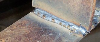
As we can see, the maximum load value is 490 MPa. Let's take the thickness 3mm and weld the seam as in the picture.
Now let's look at the T6 connection itself.
We see that the leg exceeds the thickness of the metal by about one third. Thus, we equalize the maximum load on the seam. In this example, 490 MPa. The video shows a test of such a connection.
Practice shows that welding can withstand much stronger loads than steel itself. It happens that the welded area overheats and the structure weakens, which leads to fracture. Since the plasticity of the weld takes on part of the internal stress, try to weld with a tear on thin metal. I personally burned through it more than once. Especially when there is nothing other than the diameter of the three. And we had to weld steel 1.5 mm thick, and then in hard-to-reach places.
As for the pipeline, the most important thing is the absence of defects in the deposited metal. Otherwise, the slightest crack will eventually lead to an accident. The weld welding technique is carried out continuously, with the exception of changing electrodes. There are joints that are not rotatable and you have to work with a mirror. If the pipes are under pressure, then the load extends to the walls of the pipeline. Since the structure of the metal in the weld zone is not uniform. Such places are stretched (swollen). For example, in winter, accidents often occur in the water supply and heating pipelines.
Therefore, we answered the question of how long a weld seam can withstand after welding with electrodes using one example. If we want to achieve good results and are not afraid that the welding will burst along the seam, then use GOST standards. I mentioned a few of them earlier. As for the quality of welding in winter, this is a separate issue and more complex requirements for the technical process.
And if you want to calculate for yourself how much a seam can really withstand, I’ll give you links to good literature.
Welder's Handbook p. 353 strength calculation of welding joints.
Source
Weld seam calculators
There are specialized calculators with which, without special skills, it is easy to calculate the length of the weld and determine the optimal parameters for corner, point and butt joints.
Using the calculator, you can check all existing typical joints with loads applied to them with different forces. Calculations will help you choose the size and type of butt joint that is suitable for a specific design, as well as accurately select the material for welding. Calculations make it possible to establish the required geometric values of the weld and test it for strength.
It is not recommended to apply fatigue loads to point joints, grooved joints and electric rivets, since the calculation of such welds is not supported and the results will be inaccurate. Also, the calculations do not take into account changes in the mechanical characteristics of metals that arise due to the effects of residual stresses and temperature conditions.
Tools for checking weld dimensions
The geometric parameters of welding joints are determined using special tools that make it possible, with minimal errors, to measure the main indicators and characteristics produced by the technology of welding structures.
These tools include standard templates, universal devices and meters, the principle of which is to measure one specific parameter.
Every professional welder must have a set of measuring instruments available for taking measurements for preliminary calculations before the welding process, as well as determining the quality of the weld of the finished structure.