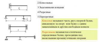
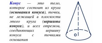
Round cone in geometry
Let us give a geometric definition of this figure. A circular cone is a surface that is formed by straight segments connecting all points of a certain circle with one single point in space. This single point must not belong to the plane in which the circle lies. If instead of a circle we take a circle, then this method also leads to a cone.
You may be interested in: Law College in Ivanovo: specialties, admissions committee, reviews
The circle is called the base of the figure, its circumference is the directrix. The segments connecting a point to a directrix are called generators or generators, and the point where they intersect is the vertex of the cone.
A round cone can be straight or inclined. Both figures are shown below in the figure.
You may be interested in: Thermophilic bacteria: benefits and harm for humans
The difference between them is this: if the perpendicular from the top of the cone falls exactly at the center of the circle, then the cone will be straight. For him, the perpendicular, which is called the height of the figure, is part of its axis. In the case of an inclined cone, the height and axis form some acute angle.
Due to the simplicity and symmetry of the figure, we will further consider the properties of only a straight cone with a round base.
Drawing a ball
The geometric shape of a ball is the simplest of all shapes, but for drawing a ball is the most difficult task. First of all, it is difficult for beginners to draw an even circle; it is difficult to achieve smooth tonal transitions when shading, so that the ball in the drawing does not have dents. The ball can be illuminated with natural light from a window or soft light with a diffuser. This light is better, it does not produce harsh shadows.
When illuminated with an incandescent lamp, the contrast is stronger, which often leads to beginners depicting the ball as too dark, as if it were not made of plaster, but of lead.
Below is a finished drawing of the ball. Images of step-by-step work, construction of shadows, explanations of the nature of reflexes will appear on the site later.
After you have mastered the drawing of geometric bodies individually, you can begin to draw a group of geometric bodies. As a rule, the composition includes a cube or parallelepiped, 1-2 bodies of rotation and a ball. Drawing a jug is also done after the student is able to draw simple geometric shapes.
Copying of articles is permitted only if there is an active (clickable) link to the source page of Denis Gavrilov’s website gavrilovart.ru and with attribution. The link must be located directly next to the material, must be visible and direct (without the use of java scripts). It is prohibited to change, erase, or cut off copyrights in photographs or illustrations copied from my site in any way.
Getting a shape using rotation
Before moving on to considering the development of the surface of a cone, it is useful to learn how this spatial figure can be obtained using rotation.
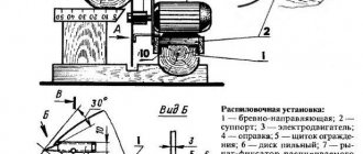
Suppose we have a right triangle with sides a, b, c. The first two of them are legs, c is the hypotenuse. Let's place the triangle on side a and begin to rotate it around side b. The hypotenuse c will describe a conical surface. This simple technique for obtaining a cone is shown in the diagram below.
Obviously, leg a will be the radius of the base of the figure, leg b will be its height, and hypotenuse c corresponds to the generatrix of a round right cone.
Features of constructing geometric shapes
Drawing geometric shapes with a pencil has the following stages:
| № | Stage | Description |
| 1 | Model Analysis | It is necessary to imagine the figure as a frame of points and lines. Drawing invisible lines is the main methodological technique that helps to draw complex models. |
| 2 | Sketching lines and vertices | To do this, you need to make light sliding movements with the pencil, without pressing too hard. |
| 3 | Identification of visible edges | Lines that are visible to the viewer should be drawn in detail. For example, if a ball or cone is depicted, then the edges of the shape are drawn in detail. |
| 4 | Hatching | With its help you can display the location of shadows. |
Hatching
Hatching is an important element in the depiction of three-dimensional objects. With its help, the artist conveys the shadow.
The rules that a novice creator should remember are the following:
- Hatching is performed only according to the shape of the object. Sometimes you can combine hatching, which helps to enhance the shadow.
- Filling with strokes should begin with the shadow areas. If this is a cube, then 1 of its faces should be filled with strokes, and the edges of the cube will become the border of light and shade. In the case of a ball, cylinder and cone, the boundaries are not clear, but more blurred.
- It is better to give preference to vertical shading. You should start from the nearest part and then move further - deeper into the drawing, while reducing the pressure with the pencil. This makes the stroke lighter and it becomes noticeable how the surface gradually goes into the distance.
- You need to start shading the illuminated area away from you.
Light and shadow
Any shadow is formed if there is a light source. The artist must determine in advance where exactly this source is located and from which side the rays fall on the object. If you have difficulties with chiaroscuro when drawing, you should practice on a simple version.
You can use one of 2 techniques - shading or shading. Before work, it is recommended to turn on the light, which will be directed at the subject. It is also important that there are no other, brighter light sources in the room.
A novice artist must remember that there are the following areas in the drawing:
| Plot | Description |
| Blik | The part of the design that reflects the light of a lamp or sunbeam. |
| Light | Areas illuminated by rays at right angles. |
| Penumbra | Areas located between light and shadow. They are also called intermediate. |
| Shadow | These are not illuminated areas. |
| Reflex | This is an illuminated area that is obtained from nearby objects. The brightness of the incident light plays a huge role: the brighter it is, the more saturated the shadow will be. |
| Falling shadow | The shadow of the figure on what is around. For example, on a horizontal surface where a figure or a wall near it is located. |
It is important to be able to find the boundary between light and shadow. Its shape depends on the image being drawn. For example, on a ball there is one boundary, and on a cube there is another. The problem with finding the boundary is that it is usually blurry. Occasionally it is clear: the brighter the light, the clearer the border.
For example:
- if you look at the ball under bright direct rays, you will notice that the border of chiaroscuro has a bend and looks like an oval;
- in the case of a cylinder, the boundary will turn into a straight line;
- on a cube this boundary runs straight along the edge.
In fine arts, a technique called “chiaroscuro” is used. It is based on the contrast between illuminated and shadowed areas. Artificial lighting creates an environment where the light is too bright and the shadow is very dark, creating saturation and harshness.
Cone scan type
As you might guess, the cone is formed by two types of surfaces. One of them is a flat base circle. Let's assume it has radius r. The second surface is lateral and is called conical. Let its generator be equal to g.
If we have a paper cone, then we can take scissors and cut off the base from it. Then, the conical surface should be cut along any generatrix and unfolded on a plane. In this way we obtained a scan of the lateral surface of the cone. The two surfaces, along with the original cone, are shown in the diagram below.
Below right is the base circle. An expanded conical surface is shown in the center. It turns out that it corresponds to a certain circular sector of the circle, the radius of which is equal to the length of the generatrix g.
Properties of developments
The development of a curved surface Ф is a flat figure obtained by combining the surface Ф with the plane Σ (Fig. 5.1). In descriptive geometry, the Σ plane is one of the projection planes.
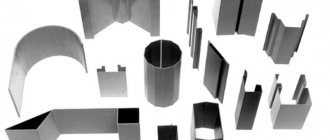
Unfolding the surfaces of bodies is widely used in technology, since a large number of technical structures are made of sheet material. Blanks of such structures, which are reamers, are used for the manufacture of thin-walled containers, blowers, industrial ventilation and pneumatic transport, shaped parts of dust collectors, parts of lifting and transport devices, etc. (Fig. 5.2).
Surface development
Application of sweeps
Surfaces Ф, which can be combined with the plane Σ without breaks or folds, are developable. These include all polyhedra (see clause 4.1), cylindrical and conical surfaces (see clause 3.2.1.3, Fig. 3.55 b - c), torsos (see clause 3.2.1.3, Fig. 3.57). All other curved surfaces do not develop onto a plane, therefore, when they are made from sheet material, they are approximately replaced by developable surfaces (prisms, pyramids, cylinders, cones). In these cases, so-called conditional sweeps take place (see clauses 5.4.1.3 – 5.4.1.4).
Basic properties of sweeps:
a) straight line l on the surface Ф corresponds to a straight line on the development
b) parallel lines on the surface Ф correspond to parallel lines on the development
c) the length (natural value) of any line s on the surface Ф is equal to the length of the line on the scan
d) the angle α between the lines r, s on the surface Ф is equal to the angle between the lines on the scan
e) the area S of a figure on the surface Ф is equal to the plane of the corresponding figure on the development
f) if the straight line on the development corresponds to the curved line s on the surface Ф, then the curve s is a geodesic line of the surface Ф. The length of the arc MN of the geodesic line is the smallest of all possible arcs MN on the surface Ф.
The described properties are geometrically interpreted in Fig. 5.3.
Properties of developments
A geodetic line (from the Greek γεωδαισία - division of the Earth) is a line of minimum length drawn through two points on a curved surface. On the surface development this line is straight.
The geodetic line is widely used in non-Euclidean geometry, theoretical and practical problems of geodesy - a science that studies the dimensions of space, including the size and shape of the Earth, its gravitational field, etc.
Angle and area of scan
Now we obtain formulas that, using the known parameters g and r, allow us to calculate the area and angle of development of the cone.
It is obvious that the arc of the circular sector shown in the figure above has a length equal to the circumference of the base, that is:
l = 2*pi*r.
If the entire circle of radius g were constructed, its length would be:
L = 2*pi*g.
Since the length L corresponds to 2*pi radians, then the angle at which the arc l rests can be determined from the corresponding proportion:
L ==> 2*pi;
l ==> φ.
Then the unknown angle φ will be equal to:
φ = 2*pi*l/L.
Substituting expressions for lengths l and L, we arrive at the formula for the angle of development of the lateral surface of the cone:
φ = 2*pi*r/g.
The angle φ is expressed here in radians.
To determine the area Sb of the circular sector, we will use the found value of φ. We make another proportion, only for areas. We have:
2*pi ==> pi*g2;
φ ==> Sb.
Where should Sb be expressed, and then substitute the value of the angle φ. We get:
Sb = φ*g2*pi/(2*pi) = 2*pi*r/g*g2/2 = pi*r*g.
For the area of a conical surface we have obtained a fairly compact formula. The value of Sb is equal to the product of three factors: pi, the radius of the figure and its generator.
Then the area of the entire surface of the figure will be equal to the sum of Sb and So (the area of the circular base). We get the formula:
S = Sb + So = pi*r*(g + r).
Frustum Geometric Object
A truncated figure is an object in space that consists of two bases of different areas and a conical side surface. Unlike the original cone, its truncated version has no vertex. The remaining linear elements for it are the same as for a cone with an apex. The truncated figure also has two directrixes that bound each of the bases, and one generatrix that rests on the lines of the directing curves.
The geometric object in question also comes in several types (elliptical, inclined). Most often in geometry problems one encounters a round straight truncated cone, which is bounded by two round bases.
Construction methods
There are two main ways to construct a truncated circular geometric object:
- from a round straight cone;
- using a trapezoid.
In the first case, it is necessary to take a conical figure and a cutting plane that will be parallel to the base. After this, use a plane to cut off the upper part of the cone. The figure remaining under the plane will be truncated. It should be noted that it does not matter at all which part of the cone with the apex will be cut off. The larger it is, the closer to each other the values of the upper and lower radii in the truncated figure will be, that is, the closer it will be in shape to a straight cylinder.
The second way to obtain a truncated conical object is using a rectangular trapezoid shape. Such a trapezoid consists of two parallel segments that have lengths a and b. They are connected by one perpendicular h and an oblique segment g.
If you place a rectangular trapezoid on a larger base and rotate it around the perpendicular h, you will get a truncated cone. In it, the segments a and b will be the radii of the bases of the volumetric figure, the perpendicular h will be the height, and the inclined segment g will be the length of the generatrix. These four linear characteristics define the volumetric figure in question. It should be noted that to unambiguously construct a figure, only any three of them are enough, for example, height and two radii.
Surface area
The surface of a truncated figure, in contrast to a full cone, is formed by three parts: two round bases and a side surface. The areas of circular bases are calculated using the well-known formula for a circle: pi*r2. For the side surface, perform the following steps:
- Cut it along the generatrix and unfold it on a plane.
- Please note that the resulting figure is a sector of a circle with another small sector cut out in its upper part.
- Mentally complete the truncated figure to a full cone and determine its height H and directrix G. Through the corresponding parameters of the truncated cone, they will be expressed as follows: G = r1*g/(r1-r2), H = h*r1/(r1-r2) , here the radii of the bases r1 and r2 are such that r1>r2.
- Calculate the areas of the large and small circular sectors, and then subtract the second from the first. The result is the following simple formula: Sb = pi*g*(r1 + r2).
The area of the entire surface of the figure in question is calculated as the sum of three quantities S1, S2 and Sb:
S = S1 + S2 + Sb = pi*r12 + pi*r22 + pi*g*(r1 + r2).
To determine the value of S, it is necessary to know three linear parameters of the truncated cone: the radii of the bases and the length of the generator.
Volume formula
To determine volume, you should use techniques similar to those described in the method for determining surface area. First, you should build the truncated cone to a full one, then calculate the volumes of figures with heights H and Hh using the already known formula. The difference between these volumes will give the desired formula for a truncated figure with round bases:
V = 1/3*pi*r12*H – 1/3*pi*r22*(Hh).
Substituting into this expression the equality for the height H through the linear characteristics of the truncated figure, we can obtain the final formula:
V = 1/3*pi*h*(r12 + r22 + r1*r2).
This expression can be rewritten not through linear parameters, but through the areas of the bases of the figure S1 and S2:
V = 1/3*h*(S1 + S2 + (S1*S2)^0.5).
The written volume formula can be obtained in a universal way without using the known expression for a full cone. To do this, it is necessary to use integral calculus, breaking the truncated geometric object into an infinite number of thin round disks. Their radii will gradually decrease from r1 to r2. This method of deriving the formula for volume does not differ from that for a complete circular cone; only the limits of integration change.
Constructing a cone scan on paper
To complete this task you will need a piece of paper, a pencil, a protractor, a ruler and a compass.
First of all, let's draw a right triangle with sides 3 cm, 4 cm and 5 cm. Its rotation around a leg of 3 cm will give the desired cone. The figure has r = 3 cm, h = 4 cm, g = 5 cm.
Let's begin constructing the development by drawing a circle of radius r with a compass. Its length will be equal to 6*pi cm. Now next to it we will draw another circle, but with radius g. Its length will correspond to 10*pi cm. Now we need to cut off a circular sector from the large circle. Its angle φ is equal to:
φ = 2*pi*r/g = 2*pi*3/5 = 216o.
Now, using a protractor, we plot this angle on a circle with radius g and draw two radii that will limit the circular sector.
Thus, we have constructed a development of a cone with the specified parameters of radius, height and generatrix.
Unfolding the surface of a polyhedron
The development of a polyhedron is a figure obtained as a result of sequential alignment of the faces of the polyhedron with a plane. The scan is always constructed with the outer (front) side facing the observer.
Natural edge method
According to the properties of the development (see section 5.1), all faces of the polyhedron Φ retain their length on the development, to determine which methods of descriptive geometry are used.
In Fig. 5.4 the horizontal and frontal projections of the triangular pyramid SABC are constructed. The ABC base is a horizontal level plane, therefore it is projected onto P1 in full size A1B1C1. To determine the natural values of the faces SAB, SBC, SCA, the method of rotation around the horizontally projecting axis i, which passes through the vertex S of the pyramid, is used. The segments are the actual sizes of the edges SA, SB, SC of the pyramid. The development of the pyramid is built along these edges. By cutting out a flat blank from the development contour and folding it along the fold lines and combining the edges of the same name, you can obtain the surface of this SABC pyramid.
Natural edge method
To determine an arbitrary point D of the pyramid on the development, the auxiliary segment method is used. Point D belongs to the face SAC. Through vertex S and point D a segment S-1 is drawn, point 1 of which belongs to the base ABC of the pyramid. The natural value of the segment S-1 is determined, the projection is determined on it. On the scan segment, a segment is constructed, the length of which is equal to the length of the projection
Normal section method
The normal section method is used to construct a development of prisms whose edges are straight lines.
The essence of the normal section method
The prism is intersected at an arbitrary place by the plane Σ, perpendicular to the edges. The actual size of line 1 - 2 - ... of normal section is determined. This line is a flat polygon, the number of sides of which is equal to the number of faces of the prism. Line 1 – 2 – ... unfolds to the shape of a straight segment ... On perpendiculars drawn on both sides of the points ..., parts of the natural dimensions of the edges of the pyramid are constructed, which are located on opposite sides of the cutting plane Σ.
In Fig. 5.5, two projections of a triangular prism ABCDEF with horizontal edges AD, BE, CF are given. A cutting plane Σ is introduced, perpendicular to the edges of the prism (the horizontal trace Σ1 is perpendicular to the horizontal projections of the edges of the prism). The plane Σ intersects the prism along the triangle 1 – 2 – 3, the points of which belong, respectively, to the edges AD, BE, CF. The natural value of the normal section is determined by the method of replacing projection planes (the axis is parallel to the trace Σ1). The triangle is unfolded to the shape of a straight segment whose parts are equal in length to the corresponding sides of the triangle. On perpendiculars drawn on both sides of the points, segments of length are constructed whose lengths are equal to the lengths of the projections. On the unfoldment, the natural values of the bases ABC, DEF of the prism are completed.
Normal section method
To determine an arbitrary point G of a prism on a scan, the method of auxiliary segments is used. Point G belongs to face ABDE. Through point G, a segment 4 - 5 is drawn, parallel to the edges of the prism. Point 4 belongs to segment AB, point 5 – to segment DE. The intersection point 6 of the segment 4 – 5 with the plane Σ is determined. Point 6 belongs to the segment 1 – 2. The projection is determined. On the development segment, a segment is constructed, the length of which is equal to the length of the projection. From the development point of the prism, a segment is drawn in the direction perpendicular to the segment towards the point. The length of the segment is equal to the length of the projection
Rolling method
The rolling method is used to deploy a prism, the base of which is parallel to one projection plane, and the side edges are parallel to another projection plane.
From points 1, 2, ... base ... of the upper face of the prism, rays are drawn perpendicular to the side edges ... Points are constructed on these rays ... so that the lengths of the segments ... are equal to the natural sizes of the segments , ...
In Fig. 5.6 two projections of a triangular prism with a base 1 – 2 – 3 and an upper edge of the horizontal level and edges of the frontal level are given. From the frontal projections, rays are drawn perpendicular to the frontal projections. On these rays, points are laid out in turn so that the lengths of the segments are equal to the natural sizes of the segments
Rolling method
To determine an arbitrary point A of the prism on the scan, the auxiliary beam method is used. Point A belongs to the face. Through point A, a segment is drawn parallel to the edges of the prism, point 4 of which belongs to segment 1 - 3 of the base. From the projections, rays are drawn perpendicular to the frontal projections of the prism ribs. From a point belonging to a scan segment, draw a segment parallel to the segment until it intersects with the ray
Drawing Geometric Solids of Revolution
Geometric bodies of rotation begin to be drawn only after mastering the image of a cube. Initially, the figures are depicted separately, then they try a still life.
To successfully draw complex shapes, start with simple ones. Models can be purchased at the store or made on your own. For this, cardboard or thick paper is used.
Figures cannot be replaced with photographs: drawing three-dimensional figures from a flat surface is meaningless and has no benefit.
Cone
The word "cone" is of Greek origin. It translates as “pine cone.” The figure was given this name because it looks like a cone or a cap.
If expressed in mathematical language, this figure is a symmetrical body, which is formed as a result of the union of rays originating from the 1st point (the vertex of the cone) and passing through a flat surface.
The base is a circle. If you place the cone model with its base on a horizontal surface and look at it from the side, it will appear before your eyes as a triangle.
However, depending on the angle at which the figure is viewed, its lower part may turn into a semicircle, so when depicting a cone, the viewing angle should be taken into account. It is also important from which side the light falls on the figure for subsequent shading.
Drawing geometric shapes in pencil: cone
To draw a three-dimensional geometric figure of a cone with a pencil as follows:
- Outline the location and size of the figure, which should not be very small or, conversely, large. The cone is located above the middle of the sheet: its upper part is optically lighter due to the larger free space.
- Outline the top of the figure and draw a horizontal line. It will act as the axis of the base.
- Mark the width of the base with serifs.
- Draw a vertical line through the center of the figure.
- Connect the vertices to the base.
- Visually make the outer lines distant from the viewer by making them lighter.
- Construct an ellipse: to convey volume, the near part of the oval should be darker.
- Continue working on the volume. To do this, find the boundary of shadow and light at the top of the figure and passing to the base. The top of the line should be clear, and its distant edge should be lighter.
- Perform shading, moving vertically from the top and reaching the base. To better convey the shape, introduce shading horizontally as well.
- Indicate the contrast of light and shadow by making the upper part lighter. From the horizontal surface on which the figure is installed, highlight the shadow part.
Cylinder
The cylinder has 2 bases - at the bottom and at the top. Both of them are shaped like a circle and are absolutely equal in size. The generatrix of the cylinder is a vertical located perpendicular to the base.
Drawing geometric shapes in pencil: cylinder
Drawing geometric shapes with a pencil in the shape of a cylinder is performed in the following order:
- On the sheet, mark the location of the object and use light shading to reveal the volume of the form. There is no need to press too hard on the pencil, especially when drawing construction lines. It is better to keep the use of an eraser to a minimum.
- Determine the height and width of the figure.
- Guide the axle. It should divide the figure in half.
- Make sure that the upper ellipse is slightly smaller. When looking at the model, it is easy to notice that the upper base is deployed less.
- Go to work with chiaroscuro. Its border is drawn vertically from one base to another. Considering the smoothness of the change in shape, make the border blurry. The stroke follows vertically. The areas that move away become darker in the light and become lighter in the shadows. The upper ellipse falls into the penumbra region if the light source is on the side.
- Specify the form. For this purpose, hatching in the horizontal direction is used. Since the top part is close to the light, it should be a little lighter.
Ball
A ball is considered the simplest figure; it is not for nothing that all planets and stars acquire this shape under the influence of the forces of nature. However, depicting a ball is not an easy task.
The first difficulties may arise with drawing a circle, then you have to deal with serious problems that appear when shading.
Drawing geometric shapes in pencil: ball
Before work, it is recommended to illuminate the ball model with soft light. In this case, there will be no sharp shadows, which will greatly simplify the task.
The sequence of drawing the ball is as follows:
- Draw a circle that will become the basis of the figure. Draw a line in the center of the paper, and put a dot in the center of this line. Draw 1 more straight line through it, perpendicular to the 1st one. When drawing these lines, you do not need to press hard on the pencil. The extreme points of the lines must be connected to form a circle.
- Apply shadows. You need to determine where the light is coming from and place a point in the most illuminated part. The width of the shadow must be marked with shading.
- Draw the diameter through the center of the figure perpendicular to the rays of light.
- Draw an ellipse based on the diameter. It marks the boundaries of chiaroscuro.
- The surface of the figure is conditionally divided into several areas depending on the degree of illumination. The lightest area is the highlight and can be left unpainted. There is a light spot around it, and then gradually move to the shadow. You need to depict the shadow with arched strokes.
To draw still lifes from geometric shapes you need:
- Prepare 3-4 figures with different characteristics. For example, it could be a cube, a sphere and a cylinder.
- Arrange the figures and prepare the drapery of the fabric on which they stand.
- Set to calm, diffused lighting.
- Select an angle for drawing. It is better if it is frontal.
- Decide on the location of the drawing and get to work.
For a beginning artist, drawing geometric shapes with a pencil is like learning the alphabet for those learning a language. This training will help in the future when creating complex figures and compositions on paper.
Determining diameter through volume and height
Now we will show how to find the diameter of a cone, knowing its volume V and height h. To do this, it is necessary to remember that the volume of a cone, like the volume of any pyramid, can be determined using the following equality:
V = 1/3*S*h
Here S is the area of the base. Since the area of the base in the case under consideration is the area of the circle, this expression can be rewritten as follows:
V = 1/3*pi*r2*h
It remains to express the radius from here and multiply it by two times, and we will get the answer to the question of how to find the diameter of the cone through the quantities V and h. We have:
r = √(3*V/(pi*h));
d = 2*r = 2*√(3*V/(pi*h))
Note that on the right side we get the length dimension. This proves the correctness of the resulting formula.
All formulas written in the article for the diameter d of the figure are also valid for the radius, which will be half the diameter.
How to build a cone?
In order to get started, let's decide on the materials:
- thick paper or drawing paper;
- simple pencils (hard, medium, soft);
- eraser;
- cutter.
It is best to draw on a vertical plane to avoid distortion.
Stage 1.
We outline the composition of the cone with a simple pencil - its location in the space of the sheet. The cone should not stick to the edges; there should be free space on all sides.
When drawing from life, stick to the proportions of the real object.
Stage 2.
Freely set the width of the base of the cone, then insert this width into the height of the cone and draw a perpendicular axis in relation to the base.
Stage 3
We are building a base - it is an ellipse, its opening depends on its location relative to the horizon line. Disclosure can also be understood by tilting the pencil.
Stage 4
From the height of the cone we draw straight lines that touch the ellipse.
Online cone surface area calculator
The point that is the beginning of these rays is called the vertex of the cone. In the case where a polygon lies at the base of the cone, the cone turns into a pyramid.
The cone consists of some elements that you need to know to solve problems.
The generatrix is a segment connecting a point lying on the circumference of a circle, which is the base, and the vertex of the cone. Height is the distance from the base plane to the apex point of the cone.