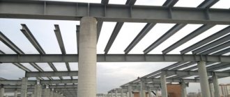
An I-beam is a type of shaped metal product that can take greater loads compared to an angle and a channel. In private construction, rolled metal with an H-shaped section is used only when creating large-sized buildings. To select the appropriate I-beam number, professional calculations of strength and deflection are performed using formulas or using an online calculator. The initial data are: span length, type of beam fastening, nature of the load, planned placement step of the profile bars, presence or absence of additional supports, steel grade.
What parameters may be needed for the calculation?
Initially, you need to know the following parameters, without which it is impossible to make a calculation:
- The length of the I-beam (the distance between the walls, taking into account their thickness, the beam must lie freely and be fixedly attached);
- Approximate load on the floor (taking into account the upper residential floor, furniture above, on the roof - precipitation, snow, which will exert pressure in winter);
- Pitch (the distance through which I-beams are laid parallel to one another; the recommended value is 1 m, in rare cases it can be increased to 1.2 m).
see also
Comments 39
For some reason, one truss was initially laid, which bears all the snow and structural load. It is much more rational to distribute the load across three to four trusses with a cross section of 300 mm, made of 40x25 corrugated pipe with struts made of 14 mm reinforcement. During installation, the trusses are tied together with cross braces for stability. Then you can lay the floor of the second floor on them. Something like that. In fact, there was already a proposal above to contact engineers. On your turbogenerator they have not yet disappeared. Hello Lysva! I was on a business trip with you about 40 years ago...
There is such a calculator vladirom.narod.ru/stoves/beamcalc.html, although for wooden beams, you seem to have them, it might come in handy! In general, it’s better to pay the company, let them do the calculations for you, it’s quite quick and the money will most likely come out to no more than 1-2 thousand rubles.
Oh, these advisors. They just come up with a lot of things. Perm - 5th snow region = 320kg/m2. Wooden floor structure = 15 kg/m2 Useful load on the floor (people, furniture) = 100 kg/m2 Blood structure (on the side) = 30 kg/m2 Beam load area = 6.61 m x (7.61/2) = 25.2 m2 . Total load on the entire length of the beam = 465 kg * 25.2 m2 = 11.7 t. Uniformly distributed load = 11.7t / 6.61m = 1.78t. (per linear meter).
Result of selection of elements: - I-beam - 40B1. — I-beam — 30Ш1. — I-beam — 20K2. - Channel — The selection could not be made. Great deflections.
I advise you to use 30Ш1 - it has a larger shelf width. It will be easier to do the support. My pleasure.
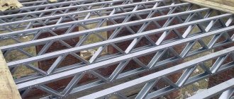
And instead of the “I-beam - 30Ш1”, isn’t it cheaper to calculate and weld a truss? A truss without calculations can cost 50-100% more due to the use of a too large profile.
Don't make things up. Truss 6.6 m long. from the corners in tonnage will weigh 200-250kg + work to make the truss. The I-beam weighs 380 kg. Where is the 100% benefit here? In addition, the truss structure has a height of 600-800mm, which reduces the height of the ceiling. Is it necessary? Do not mislead people if you are not competent in the matter. Trusses can be rationally used in large span buildings. For a garage this is absolutely pointless. I’m telling you this as a design engineer.
I meant that a farm without calculations can cost 50-100% more than a calculated farm. As a rule, without calculation, stronger rolled products are used than required by calculation. And an extra 3-5 times safety margin may be impractical.
If the roof structure did not rest on a beam (floor), it would be easy to calculate which channel or I-beam to use, but with such a roof structure, the entire bulk of the roof rests on the calculated beam.
I would prefer to weld two channels instead of 2t
Cook the farm. Don't make things up. I have about 100 professional pipes, but that’s a lot. From 60 it will be normal.
To avoid future troubles in the form of collapse of the ceiling or severe sagging of the beam and further destruction, I would entrust the calculation to a civil engineer. And if you listen to amateurs, it will be scary to enter this garage (especially in winter after a heavy snow load on the roof).
Examples of calculated resistance
To calculate an I-beam, a value such as design resistance (Ry) may be required. It depends on the grade of steel from which the beam is made. For example, here are the ready-made values:
- C 235 - 230 MPa;
- C 345 - 335 MPa;
- From 255 - 250 MPa.
The elastic modulus is taken as one value, equal to steel: E = 200,000 MPa. The calculation of the load of an I-beam is carried out on the basis of load-bearing capacity calculations. To this figure add 30% for strength (this applies only to welded profiles).
Calculation of the load on an I-beam - relevance of implementation and basic methods
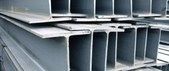
I-beam, as one of the varieties of shaped ferrous and non-ferrous metal products, is distinguished by a wide range of products.
Therefore, during the design and further construction of structures using an I-beam, the right choice must be made. It must be based on correct calculations. Read our article on how to calculate the load on an I-beam. Let us immediately note that for the calculations you will need formulas, tables and knowledge. And if they are not there, then it is better to entrust everything to an experienced and qualified engineer. Especially when it comes to an I-beam, which is used in loaded structures.
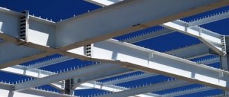
Both the quality of construction and the safety of operation of the facilities being built directly depend on this. All parameters must comply with current regulatory documents and ensure the design performance characteristics of the metal structure. This is due, first of all, to the scope of application of the I-beam, for example, as a floor element.
Selecting a profile number (examples)
According to the table, according to which the number is selected according to the expected load, span and pitch, the following profile models are selected:
- Number 16 (with a load of 300 kg/m.p., span 6 m, step 1 m);
- Number 20 (with a load of 400 and 500 kg/m.p., span 6 m, pitch 1.1 m and 1.2 m);
- Profile number 10 (with a load of 300 kg/m.p., span 4 m and 3 m, step 1 m).
The design load on an I-beam is calculated as follows:
- 1. The pressure on the floor, including the weight of the floor itself, is recalculated per 1 linear meter of beam.
- 2. The resulting number is multiplied by the reliability coefficient according to GOST 8239-89.
- 3. Based on the load, the moment of resistance is found (according to the table of basic design values GOST 8239-89).
- 4. Based on the moment of resistance, the number of the profile from the assortment is determined in accordance with GOST 8239-89. In this case, it is better to choose a number 2 values higher.
It should be noted that the bearing capacity takes into account the design load, but not the standard one. Also, the load-bearing capacity is taken when calculating bending.
What can a correct load assessment and selection of the appropriate I-beam marking give?
The main thing that a correct assessment of the load on I-beam structures and the selection of the appropriate class of rolled steel gives is the economic efficiency of construction. Costs will be optimal, all safety requirements and floor strength criteria will be met. You can get additional benefits:
- significantly increase the size of free spans;
- reduce the weight of load-bearing structures, this figure can reach 35% when switching from a square profile to an I-beam;
- increase profitability by obtaining the planned final characteristics of the implemented project as a whole.
In order to increase the load limit that an I-beam can withstand, auxiliary means and methods are used. This could be, for example, creating additional stiffeners or strengthening existing ones. The latter method is used for long I-beam structures only in the longitudinal direction.
Taking steel grade into account when determining strength
When calculating strength, the grade of steel is taken into account. For difficult climatic conditions, the I-beam is made of non-brittle steel. It is better to choose the most durable brands. Here it should be taken into account that a product of higher strength may have smaller dimensions and, therefore, the permissible pressure will be less.
That is why a competent calculation of strength is performed in several different versions, then the parameters are compared. To determine the strength, it is necessary to decompose the applied force along the axes and determine the maximum moments around these axes.
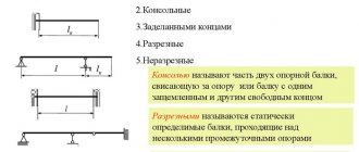
Typical I-beam layouts
One of the initial parameters taken into account in the calculations is the beam fastening scheme and the type of applied load. Most options come down to basic schemes:
- a simply supported beam with a uniformly applied load;
- with rigid sealing of one end, the force is distributed evenly;
- single-span with a cantilever on one side, with additional support, the load is evenly distributed;
- hinged-supported, concentrated force;
- hinged-supported, with two applied forces;
- console with rigid embedding, concentrated force is applied.
Definition of deflection
In order to calculate the deflection of an I-beam structure based on deformations, you need to know the following parameters:
- Design load (kg/m);
- Standard load (kg/m);
- Overlapping length (D);
- Design resistance (MPa).
It should be noted that the deflection of the I-beam structure should not exceed the following values:
- 1/250 (when used for interfloor ceilings);
- 1/200 (if used for lintels, attics).
Construction of diagrams Q and M
A detailed example of constructing diagrams of transverse forces Q and bending moments M for a beam
Internal force factors Qy and Mx in the beam span 0 ≤ z2 ≤ l
QII= — RB+ qz2= -52+30∙z2 QII(z=0)= -52 kN QII(z=l)= -52+30∙4=68 kN
MII=RB∙z2-qz22/2=52z2-30∙z22/2 MII (z=0)= 0 MII (z=l)= -32 kNm
On the console l ≤ z1≤ (l+a)
QI= — RB+ ql — RA=-52+30∙4-108=-40 kN
MI=RB z1-ql(z1-l/2)+RA(z1-l)=52z1-30∙4(z1-4/2)+108(z1-4) MI (z=l)= -32 kNm MI (z=l+a)= 0
Based on these data, diagrams of Q and M were constructed.
How to replace calculating deflection?
When building a small house in private construction, it is not necessary to find all the values for complex calculations. Some parameters may not affect the quality of construction at all. For example, for a small house or dacha, one of two values is determined:
- Deflection of an I-beam;
- Load bearing capacity.
At the same time, it is not necessary to calculate deflection in private construction. However, its value is used when choosing a finish for the ceiling, since it is better not to use heavy materials under unfavorable conditions.
Selection of the cross-section of an I-beam
The fulfillment of production tasks depends on how correctly the parameters of the I-beam section are calculated. This is a very important point, because it determines the safety of many people. The main parameters of the I-beam section are:
- Overall height.
- Wall thickness.
- Shelf width. Each one is measured.
- Shelf overhang. This is the width of its part from the wall to the edge.
- Shelf thickness with parallel edges.
- The thickness of the shelf with the slope of the internal edges.
- The radius of curvature of the shelf edge.
- Radius of internal rounding. This is the rounding of the transition from the wall to the shelf.
The specified parameters are calculated taking into account SNiP, beam production technology, grade and type of steel. In the latter case, knowledge of the strength of materials is used. After all, it is necessary to determine the dynamic and static loads that a certain beam can withstand. All this involves complex engineering calculations.
Such cranes are made from I-beams. The cross-sectional calculations determine what loads the beam will withstand.
When choosing a supplier of I-beams and other rolled metal products, it is worth considering not only the benefits from the terms of cooperation, but also the quality of the products. In some cases, you can contact the manufacturer for advice.
General formula for deflection
It is important to understand that deflection occurs at corners of turns. It depends on the purpose of the structure, its dimensions, steel grade, and physical characteristics of the product. The calculation is carried out using many formulas, but in general the equation looks like this:
Fх = -0аX + Мx2/2ЕI + Ax3/6ЕI - qх4/24Е/
However, the correct calculation of deflection depends on the type of load. In this case, the calculation of the I-beam structure is provided for downward deflection. This means that the center of gravity moves along the y-axis. If different forces act on the floor, deflection calculations are carried out for each of them. At the end of the calculations, all results are summed up.
Such techniques make it possible to determine the parameters for deflection under any loads. However, it is not always advisable to make such calculations, since these quantities do not always have meaning. For example, for a private small house or cottage, it is not necessary to calculate the deflection.
Load collection
To carry out calculations for limit states in terms of strength and deflection, all forces that will act on the I-beam are determined. These include:
- Permanent. Own weight of the metal profile and ceiling.
- Temporary. These include three types of efforts: long-term, short-term, special. Long-term ones, for example, include a lot of temporary partitions. Short-term - the weight of people, wind, snow and other influences. Special – explosive, volcanic.
Attention! In buildings where the slope angle exceeds 60°, the impact of snow cover is not taken into account.
There is another division of effort - into calculated and normative, determined by normative documentation.
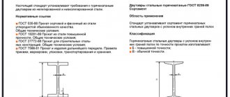
I-beam profile No. 18: distinctive features and weight of the I-beam
This type of profile is classified as shaped rolled products - in the category of monorail beams. I-beam 18 is considered to be universal, since it is applicable in all branches of construction. Its main advantages are rigidity, strength, and wear resistance.
Like previous types of beams, I-beam No. 18 is manufactured in accordance with state standard 8239-89. This product is made in an H-shape and is available in two versions. There are I-beams of standard and increased accuracy. The standard precision profile has a height of 180 mm, a width of 90 mm, a wall thickness of 5.1 mm and an average lintel thickness of 8.1 mm. The weight of 18 I-beams in a meter beam is 18.35 kg. The high-precision beam is characterized by its distinctive features. The marking contains the letter “A”. The dimensions of I-beam 18 in this version are slightly different. The total profile height is 180 mm. The total width is 100 mm. The lintel has a thickness of 5.1 mm, the thickness of the shelf is 8.3 mm. I-beam No. 18 19.92 kg weighs.
I-beam No. 18 is used when laying the foundation, creating supporting areas, and also as reinforcing elements
Helpful advice! To quickly understand the profile markings, it is enough to know the principle of the inscription: the first numbers are the height of the profile, the letters are the type of beam and the number at the end is the size of the beam in this series.