Metal floors are a structure used as a building material in the construction of various private and industrial facilities.
Before purchasing the material, it is necessary to make the necessary calculations and make sure that the metal floor elements are suitable for the construction of the facility.
Let's consider and understand them in more detail.
What is it and what sizes do they come in?
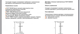
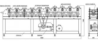
The beam is one of the main elements of any structure; its function is to increase the stability of the structure and strengthen it. A beam (or transom) consists of flanges and walls of various sizes, connected by butt seams using welding. Elements are manufactured at equipped factories using special machines.
The manufacturing procedure is carried out in several stages, after which the finished product is checked for compliance with GOST standards.
Metal structures vary in size; for convenience, they have numbers , with which you can select the necessary material for construction.
“10” is a small product, used as a ceiling to strengthen moving elements in construction. Can be used as a guide for small lifts.- “12” is a slightly larger structure size that can withstand a larger load. Used as a basis for frames, used in mechanisms.
- “14” - products of this size can be used in industrial production for installation in reinforced concrete structures.
- “16” is a durable structure that acts as a full-fledged support and can be used to move vehicles around the workshop.
- “18” is a reliable supporting element, used in the construction of buildings, it will ensure the stability of a large area.
- “20” is a large element that can serve as the basis for a column or frame. Often used in mechanical engineering.
- “25” - the product can serve as a support for large cranes and large-sized lifting mechanisms.
- “30” is the largest structure not used in residential construction. It is the basis for lifting mechanisms.
Scope of application
Metal floor beams have found their application in various fields. Can be used for :
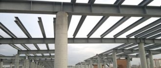
- Roof strengthening in residential and industrial construction.
- Creation of interfloor ceilings.
- Construction of supports and various columns in industrial structures and architectural buildings.
- Installation of hangar frames.
- Mine shafts.
- Creation of various railway cars.
- Construction of bridges, overpasses.
- Construction of metal trusses.
Note : metal floor beams can also be used in the construction of low-rise private houses.
Welded, bolted and riveted floor beams
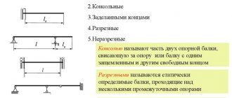
This option is used when the dimensions of the metal floor beams differ from the standard ones or the rolled I-beams do not satisfy the design conditions for overall stability, rigidity or strength. In addition, preference is given to “prefabricated” beams if they are more economical or have a better level of performance characteristics.
The most commonly used is a welded beam, which is made by automatic submerged arc welding. At the preliminary stage, cutting, cleaning and straightening of the metal, cutting edges for welding are carried out, and then, directly, the process of connecting the elements into a single whole. After welding, the finished product is straightened to eliminate thermal deformations (mushroom shape).
In this way, it is possible to obtain not only standard sizes, but also products of variable cross-section, reinforced or bistal I-beams.
Varieties
Metal structures differ in many ways. It is recommended to take this into account when choosing a product.
By purpose
Using metal beams, you can create a high-quality durable floor by choosing one of the options.
Monolithic . Concrete is poured into the formwork and reinforced with a grid of reinforcement. The surface is seamless and highly durable.- Monolithic-prefabricated . In this case, in addition to metal beams, concrete blocks are used, which are laid on a steel profile. The joint areas are filled with concrete.
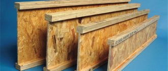
- Composite . A combination of materials is used, that is, slabs, boards, and panels are laid on load-bearing metal products. This option involves the creation of additional insulation and sound insulation of the surface.
By material: steel and aluminum
Metal structures can be made from different materials. The most popular are steel and aluminum floor beams.
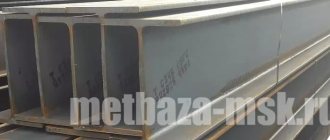
- Steel products are made from steel alloy by cold or hot rolling.
Steel structures come in several types: angle, channel, I-beam. The advantages of steel beams include fire resistance, resistance to rotting and external factors, and high strength. The main disadvantages are: high cost, low heat and sound insulation, risk of corrosion. Installation of steel structures cannot be carried out without the use of special equipment. - Aluminum beams . In their manufacture, not just aluminum is used, but its alloys. In construction, such products are used less frequently than their steel counterparts, since they are inferior in terms of stability under heavy loads. Most often, aluminum beams are used in the construction of small-sized buildings. When constructing industrial facilities, products made from this metal are used only in combination with steel structures.
By design
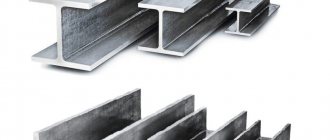
In modern construction, several types of metal beams are used, varying in design.
T-bars . The main section consists of a wall and a shelf in the shape of the letter “T”.- I-beam. The cross-section of rolled metal looks like the letter “H”. The product is more rigid than a T-bar due to the fact that it has an additional shelf on the opposite side.
I-beam elements are divided into several types, each of which is marked:- B – standard I-beams.
Ш – product with wide brim.
- U - narrow-flange structures.
- D – mid-shelf products.
- K – column beams. The width of the shelf of such an element can be equal to the height of the product.
- Channel . The cross section of the element is the letter “P”. These beams are considered universal and are used in all areas of industry.
There are I-beams not with parallel, but with inclined shelves. They are classified into special and ordinary. Their characteristics are regulated by GOST 19425-74.
ShT brands according to TU 14-2-685-86. Profile name, weight.
| I-beam profile name | Height (h), mm | Shelf width (b), mm | Wall thickness (s), mm | Average flange thickness (t), mm | Weight of 1 m beam, kg | Meters of beams per ton |
| Beam 13PCS1 | 122 | 180 | 7 | 10 | 21.1 | 47.39 |
| Beam 13PCS2 | 124 | 180 | 7.5 | 12 | 24.4 | 40.98 |
| Beam 15PCS1 | 142 | 200 | 8 | 11 | 26.6 | 37.59 |
| Beam 15PCS2 | 144 | 200 | 8.5 | 13 | 30.2 | 33.11 |
| Beam 15ШТ3 | 146 | 200 | 9 | 15 | 33.9 | 29.5 |
| Beam 17.5 pcs.1 | 165.5 | 250 | 9.5 | 12.5 | 37.3 | 26.81 |
| Beam 17.5 pcs.2 | 167 | 250 | 10 | 14 | 40.8 | 24.51 |
| Beam 17.5 pcs.3 | 169 | 250 | 10.5 | 16 | 45.4 | 22.03 |
| Beam 20PCS1 | 190.5 | 300 | 9.5 | 14 | 47.8 | 20.92 |
| Beam 20PCS2 | 192.5 | 300 | 11.5 | 16 | 55.2 | 18.12 |
| Beam 20pcs3 | 194.5 | 300 | 12.5 | 18 | 61.3 | 16.31 |
| Beam 25PCS1 | 238.5 | 300 | 11 | 15 | 56.9 | 17.57 |
| Beam 25PCS2 | 241 | 300 | 14.5 | 17.5 | 68.9 | 14.51 |
| Beam 25ШТ3 | 244 | 300 | 15.5 | 20.5 | 77.7 | 12.87 |
| Beam 25ШТ4 | 247 | 300 | 16.5 | 23.5 | 86.6 | 11.55 |
| Beam 30PCS1 | 286.5 | 320 | 12 | 17 | 70.7 | 14.14 |
| Beam 30PCS2 | 290 | 320 | 16 | 20.5 | 80 | 12.5 |
| Beam 30ШТ3 | 294 | 320 | 18 | 24.5 | 102.3 | 9.78 |
| Beam 30ШТ4 | 298 | 320 | 20 | 28.5 | 116.5 | 8.58 |
Column brands according to TU 14-2-685-86. Profile name and weight
Requirements
All requirements for metal beams are clearly outlined in GOSTs and SNiPs. The main requirements are :
- Durability . Depending on the type of material used in the manufacture of the product, strength indicators may differ, but they must correspond to the values specified in regulatory documents.
- Operating period . Metal structures, according to GOST, must last at least 80 years.
- Corrosion resistance . Finished elements must be additionally treated with compounds that prevent the formation of corrosion.
Checking beam strength by principal stresses
The most dangerous point in the unfavorable section is point 3. At this point σ 1 = 118 MPa and σ 3 = -16 MPa. We check the strength at this point using the third strength hypothesis according to the inequality σ 1 - σ 3≤ [ σ ].
Since 118 - ( -16) = 134 θ
whence θ = -8.48∙10 -3 radians.
Deflection in the span at z=l/2=4/2=2 m.
The deflection at the end of the console is determined similarly at z = l + a = 4 + 0.8 = 4.8 m.
Calculation of permissible stresses for bending strength.
– with a symmetrical section
Characteristics
Floor beams, depending on the production technology, have different characteristics.
I-beams with inclined shelves. The slope angle is 6-12 degrees. Main parameters:- length – 10-60 cm;
- width – 5.5-19 cm;
- shelf thickness – 7.2 mm-1.8 cm;
- wall thickness – 4.5mm-1.2 cm.
- I-beams with parallel edges (GOST 26020, STO ASChM 20-93) have other characteristics:
- length - B-1 - 100 B-4;
- shelf thickness – 5.7 mm-3.3 cm;
- profile width – 55 mm-32 cm;
- wall thickness – 4.1 mm-1.95 cm.
- Wide-flange metal structures have the following characteristics:
- length - 20Ш1- 70Ш5;
- profile width – 15-32 cm;
- wall thickness – 6.0 mm - 2.3 cm;
- shelf thickness – from 9 mm -3.65 cm.
- Column beams have the following indicators:
- length – 20 K1-40 K5;
- profile width – from 20 to 40 cm;
- wall thickness – from 6.5 to 2.3 cm;
- shelf thickness – 1-3.55 cm.
Reinforced concrete stiffeners for home
According to the standards, there are as many as 16 types of reinforced concrete beams! The four most commonly used are: rafter, with parallel belts; single slope; gable; rafter The peculiarity of such “ribs” is that they can be made not only in production, but also independently. However, there are also standards for calculations:
- reinforcement follows the scheme: rod diameter 12–14 mm, laying in 4 rows - 2 on top, 2 on bottom;
- continuous filling, in one step;
- the height of the manufactured beam is not less than 5% of the length of the opening;
- width proportion – 7 height units to 5 width units.
Reinforced concrete rafter lintel
In addition to the advantages (optimal load distribution, reliability, resistance to corrosion, durability), there are also significant disadvantages that limit the use of such floors. This requires the use of special devices and heavy weight.
Calculation
When planning the installation of a ceiling or floor using metal beams, it is recommended to correctly perform the necessary calculations.
What indicators to consider?
When carrying out calculations, a number of factors are taken into account simultaneously:
- surface area under construction;
- total weight;
- distance between metal beams;
- maximum possible load;
- span width.
The greater the span width, the greater the height of the metal products.
Formulas
The calculation is made based on the strength and rigidity of the product . By calculating the values in the GOST tables, you can find the required rental number.
Linear load is calculated using the formula q = Q * p and is used in subsequent calculations.
The deflection calculation is calculated using the formula My = (q * L2) / 8 , where:
- q – linear load value;
- p – beam laying step;
- L is the length of the overlapped span.
The maximum moment of resistance of a beam section (Wy) is found by dividing the bending moment by the design resistance of the material.
Stiffness calculations are carried out using the formula f = 5 * q * L4 / (384 * E * Jy) , where:
- q – linear load on the beam;
- L – span length;
- E – elastic modulus of the material
- Jy is the minimum moment of inertia.
Selection of I-beam section - other types of products
The selection of the profile section for a special hot-rolled profile will be different. This is largely determined by the slope of the inner edges of the shelves. GOST 19425-74 is also replaced by GOST R 57837-2017; a brilliant idea did not occur to me (just kidding). In short, there are two main types of custom I-beams. The first is M (suspended, monorail). The ratio of the base of the I-beam to the width of the shelves is approximately 2/1 or 3/1. C – for reinforcing mine shafts. The section is distinguished by a significant slope of the internal edges of the shelves.
Please note that the I-beam U is still on the market. The letter indicates that this is a narrow-flange rolled product. A characteristic feature of the section is narrow shelves.
And the last type of hot-rolled I-beam is D. This means additional. According to GOST R 57837-2017 it is marked as DK and DB. Manufactured according to customer requirements. Whatever cross-section you need will be made to order. This is especially true when there is a complex, non-trivial engineering task when designing unique metal structures. Among the characteristic features of the section is the width of the shelf. It is smaller than the width of the shelf of a wide-flange I-beam. But at the same time, the width of the flange of an I-beam D is less than the width of the flange of a normal-type I-beam. Although there are exceptions.
To sum it up let's say this. The selection of the I-beam section is determined by complex calculations. The shape of the profile depends on the basic parameters of the rolled product and determines its type. Sometimes type characteristics determine the type of section. Particular care must be taken in selecting the I-beam section for loaded structures. Still have questions? Need an I-beam? Contact us!
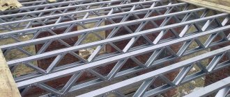
Features of the installation process
The procedure for installing floors using metal beams has certain features that must be known and strictly followed.
It is necessary to have a clear construction plan with calculations made for the strength and bending of products.- Bars with a section of 60x60 are attached to the side faces of the beams, after which a roll of boards is placed.
- The roll-up is covered with a layer of insulation that performs the functions of sound and heat insulation.
- The step between steel beams should not exceed 150 cm, the optimal distance is 100 cm.
- The depth of support of the ends of metal structures on the walls is a maximum of 25 cm.
- To achieve greater sound insulation, you can use spring brackets rather than ordinary ones.
Metal beams for columns of standard series
The Monteco company has an extensive library of drawings for columns of various standard series. The production of such products is well-established, all product indicators meet the standards, orders are completed in the shortest possible time. The company produces beams from rolled I-beams, welded I-beams, and also produces welded I-beams independently with linear dimensions according to the customer’s drawings or according to its own calculations.
The company also carries out design work on strengthening metal beams with subsequent production operations. An additional advantage of MK Monteco's offer is the possibility of installing metal beams in-house.
Welded support beam with heel
Steel beams BK, BP, BR, BS and BM
is engaged in the production of suspension beams for lifting mechanisms and crane beams; we are also ready to make load-bearing beams for technological equipment for any purpose. All design work is carried out in accordance with SNiP, and each technological operation meets industry standards (OST), standard technical conditions and enterprise standards. We produce metal structures in our own closed heated workshop, this allows us to avoid possible technological limitations.
Pros and cons of use in buildings
Metal structures have a number of advantages, due to which the material is widely used:
- increased strength;
- fire resistance;
- resistance to external factors;
- increased reliability;
- long period of operation;
- the ability to strengthen an already constructed building;
- increased load-bearing capacity.
However, such beams also have their disadvantages, which should also be taken into account :
- complexity of construction work;
- the need to use heavy equipment;
- metal may corrode;
- complex calculations are required, which can be very difficult for a beginner.
Prices for all types
In construction, I-beams are most often used. The average cost of production is presented in the table.
| Beam name | Length | Price |
| I-beam No. 10 | 12 m | 880 |
| I-beam No. 10 B-1 | 12 m | 780 |
| I-beam No. 12 | 12 m | 900 |
| I-beam No. 12 B-1 | 12 m | 660 |
| I-beam No. 14 | 12 m | 1050 |
| I-beam No. 14 B-1 | 12 m | 740 |
| I-beam No. 16 | 12 m | 1300 |
| I-beam No. 16 B-1 | 12 m | 980 |
| I-beam No. 18 | 12 m | 1280 |
| I-beam No. 18 B-1 | 12 m | 1150 |
| I-beam No. 20 | 12 m | 1560 |
| I-beam No. 25 B-1 | 12 m | 2150 |
| I-beam No. 25 Ш-1 | 12 m | 3500 |
| I-beam No. 30 | 12 m | 2600 |
| I-beam No. 35 | 12 m | 3300 |
| I-beam No. 40 | 12 m | 3500 |
| I-beam No. 45 B-1 | 12 m | 5200 |
Hot-rolled steel I-beams with parallel flange edges according to GOST 26020-83
| I-beam profile name | Height (h), mm | Shelf width (b), mm | Wall thickness (s), mm | Average flange thickness (t), mm | Weight of 1 m beam, kg | Meters of beams per ton |
| Normal I-beams | ||||||
| Beam 10B1 | 100 | 55 | 4.1 | 8.1 | 123.46 | |
| Beam 12B1 | 117.6 | 64 | 3.8 | 8.7 | 114.94 | |
| Beam 12B2 | 120 | 64 | 4.4 | 10.4 | 96.15 | |
| Beam 14B1 | 137.4 | 73 | 3.8 | 10.5 | 95.24 | |
| Beam 14B2 | 140 | 73 | 4.7 | 12.9 | 77.52 | |
| Beam 16B1 | 157 | 82 | 4 | 12.7 | 78.74 | |
| Beam 16B2 | 160 | 82 | 5 | 15.8 | 63.29 | |
| Beam 18B1 | 177 | 91 | 4.3 | 15.4 | 64.94 | |
| Beam 18B2 | 180 | 91 | 5.3 | 18.8 | 53.19 | |
| Beam 20B1 | 200 | 100 | 5.6 | 22.4 | 44.64 | |
| Beam 23B1 | 230 | 110 | 5.6 | 25.8 | 38.76 | |
| Beam 26B1 | 258 | 120 | 5.8 | 28 | 35.71 | |
| Beam 26B2 | 261 | 120 | 6 | 31.2 | 32.05 | |
| Beam 30B1 | 296 | 140 | 5.8 | 32.9 | 30.4 | |
| Beam 30B2 | 299 | 140 | 6 | 36.6 | 27.32 | |
| Beam 35B1 | 346 | 155 | 6.2 | 38.9 | 25.71 | |
| Beam 35B2 | 349 | 155 | 6.5 | 43.3 | 23.09 | |
| Beam 40B1 | 392 | 165 | 7 | 48.1 | 20.79 | |
| Beam 40B2 | 396 | 165 | 7.5 | 54.7 | 18.28 | |
| Beam 45B1 | 443 | 180 | 7.8 | 59.8 | 16.72 | |
| Beam 45B2 | 447 | 180 | 8.4 | 67.5 | 14.81 | |
| Beam 50B1 | 492 | 200 | 8.8 | 73 | 13.7 | |
| Beam 50B2 | 496 | 200 | 9.2 | 80.7 | 12.39 | |
| Beam 55B1 | 543 | 220 | 9.5 | 89 | 11.24 | |
| Beam 55B2 | 547 | 220 | 10 | 97.9 | 10.21 | |
| Beam 60B1 | 593 | 230 | 10.5 | 106.2 | 9.42 | |
| Beam 60B2 | 597 | 230 | 11 | 115.6 | 8.65 | |
| Beam 70B1 | 691 | 260 | 12 | 129.3 | 7.73 | |
| Beam 70B2 | 697 | 260 | 12.5 | 144.2 | 6.93 | |
| Beam 80B1 | 791 | 280 | 13.5 | 159.5 | 6.27 | |
| Beam 80B2 | 798 | 280 | 14 | 177.9 | 5.62 | |
| Beam 90B1 | 893 | 300 | 15 | 194 | 5.15 | |
| Beam 90B2 | 900 | 300 | 15.5 | 213.8 | 4.68 | |
| Beam 100B1 | 990 | 320 | 16 | 230.6 | 4.34 | |
| Beam 100B2 | 998 | 320 | 17 | 258.2 | 3.87 | |
| Beam 100B3 | 1006 | 320 | 18 | 285.7 | 3.5 | |
| Beam 100B4 | 1013 | 320 | 19.5 | 314.5 | 3.18 | |
| Wide-flange I-beams | ||||||
| Beam 20Ш1 | 193 | 150 | 6 | 30.6 | 32.68 | |
| Beam 23Ш1 | 226 | 155 | 6.5 | 36.2 | 27.62 | |
| Beam 26Ш1 | 251 | 180 | 7 | 42.7 | 23.42 | |
| Beam 26Ш2 | 255 | 180 | 7.5 | 49.2 | 20.33 | |
| Beam 30Ш1 | 291 | 200 | 8 | 53.6 | 18.66 | |
| Beam 30Ш2 | 295 | 200 | 8.5 | 61 | 16.39 | |
| Beam 30Ш3 | 299 | 200 | 9 | 68.3 | 14.64 | |
| Beam 35Ш1 | 338 | 250 | 9.5 | 75.1 | 13.32 | |
| Beam 35Ш2 | 341 | 250 | 10 | 82.2 | 12.17 | |
| Beam 35Ш3 | 345 | 250 | 10.5 | 91.3 | 10.95 | |
| Beam 40Ш1 | 388 | 300 | 9.5 | 96.1 | 10.41 | |
| Beam 40Ш2 | 392 | 300 | 11.5 | 111.1 | 9 | |
| Beam 40Ш3 | 396 | 300 | 12.5 | 123.4 | 8.1 | |
| Beam 50Ш1 | 484 | 300 | 11 | 114.4 | 8.74 | |
| Beam 50Ш2 | 489 | 300 | 14.5 | 138.7 | 7.21 | |
| Beam 50Ш3 | 495 | 300 | 15.5 | 156.4 | 6.39 | |
| Beam 50Ш4 | 501 | 300 | 16.5 | 174.1 | 5.74 | |
| Beam 60Ш1 | 580 | 320 | 12 | 142.1 | 7.04 | |
| Beam 60Ш2 | 587 | 320 | 16 | 176.9 | 5.65 | |
| Beam 60Ш3 | 596 | 320 | 18 | 205.5 | 4.87 | |
| Beam 60Ш4 | 603 | 320 | 20 | 234.2 | 4.27 | |
| Beam 70Ш1 | 683 | 320 | 13.5 | 169.9 | 5.89 | |
| Beam 70Ш2 | 691 | 320 | 15 | 197.6 | 5.06 | |
| Beam 70Ш3 | 700 | 320 | 18 | 235.4 | 4.25 | |
| Beam 70Ш4 | 708 | 320 | 20.5 | 268.1 | 3.73 | |
| Beam 70Ш5 | 718 | 320 | 23 | 305.9 | 3.27 | |
| Column I-beams | ||||||
| Beam 20K1 | 195 | 200 | 6.5 | 41.5 | 24.1 | |
| Beam 20K2 | 198 | 200 | 7 | 46.9 | 21.32 | |
| Beam 23K1 | 227 | 240 | 7 | 52.2 | 19.16 | |
| Beam 23K2 | 230 | 240 | 8 | 59.5 | 16.81 | |
| Beam 26K1 | 255 | 260 | 8 | 65.2 | 15.34 | |
| Beam 26K2 | 258 | 260 | 9 | 73.2 | 13.66 | |
| Beam 26K3 | 262 | 260 | 10 | 83.1 | 12.03 | |
| Beam 30K1 | 296 | 300 | 9 | 84.8 | 11.79 | |
| Beam 30K2 | 304 | 300 | 10 | 96.3 | 10.38 | |
| Beam 30K3 | 300 | 300 | 11.5 | 108.9 | 9.18 | |
| Beam 35K1 | 343 | 350 | 10 | 109.7 | 9.12 | |
| Beam 35K2 | 348 | 350 | 11 | 125.9 | 7.94 | |
| Beam 35K3 | 353 | 350 | 13 | 144.5 | 6.92 | |
| Beam 40K1 | 393 | 400 | 11 | 138 | 7.25 | |
| Beam 40K2 | 400 | 400 | 13 | 165.6 | 6.04 | |
| Beam 40K3 | 409 | 400 | 16 | 202.3 | 4.94 | |
| Beam 40K4 | 419 | 400 | 19 | 242.2 | 4.13 | |
| Beam 40K5 | 431 | 400 | 23 | 291.2 | 3.43 | |
| Additional series I-beams (D) | ||||||
| Beam 24DB1 | 239 | 115 | 5.5 | 27.8 | 35.97 | |
| Beam 27DB1 | 269 | 125 | 6 | 31.9 | 31.35 | |
| Beam 36DB1 | 360 | 145 | 7.2 | 49.1 | 20.37 | |
| Beam 35DB1 | 349 | 127 | 5.8 | 33.6 | 29.76 | |
| Beam 40DB1 | 399 | 139 | 6.2 | 39.7 | 25.19 | |
| Beam 45DB1 | 450 | 152 | 7.4 | 52.6 | 19.01 | |
| Beam 45DB2 | 450 | 180 | 7.6 | 65 | 15.38 | |
| Beam 30DSh1 | 300.6 | 201.9 | 9.4 | 72.7 | 13.76 | |
| Beam 40DSh1 | 397.6 | 302 | 11.5 | 124 | 8.06 | |
| Beam 50DSh1 | 496.2 | 303.8 | 14.2 | 155 | 6.45 |
If there are GOSTs for I-beams, then the manufacture of the T-beam is carried out according to TU 14-2-685-86
The designation here is the same as for an I-beam.
Column brands and ShT brands according to TU 14-2-685-86 have the following dimensions
ShT brands according to TU 14-2-685-86. Profile name, weight.