Every craftsman knows that to make a hole you need a special tool - a drill. Nowadays no home can do without this tool. Craftsmen who work with wood or stone constantly need to use a drill.
The most difficult thing in such cases is to make many holes accurately and evenly. At large factories for the manufacture of such products, there are special machines for drilling.
For a craftsman at home, such a huge device is of no use, so most often people make their own drilling machines.
In size, such a machine is much smaller and more compact than the factory one. It can easily be placed in a small garage or workshop. We will now look at how to make and design a drilling machine with our own hands.
To come in
Already registered? Sign in here.
There are currently 0 users on the page
There are no users viewing this page.
Those who have ever used an electric drill have encountered difficulties when it is necessary to make a bunch of holes. It's a disaster if there are holes in the board, but making holes in the metal? For this purpose, the industry came up with a drilling machine. Those who have it are very lucky, and those who don’t have it - prepare your pockets.
Personally, my pocket is small, so I can’t afford a factory drilling machine. Well, Chinese, made of tin, I can certainly afford it, but it’s bullshit. Soviet, semi-complete ones are unreasonably expensive. In principle, I didn’t consider magazine racks for drills, they were too childish. Wandering around the Internet I found a lot of homemade products, but the availability of turning work stopped me. You can order a couple of parts from a turner, but no one wants to share normal drawings, and when you design a part yourself, a mess will always come out. If a jamb comes out, run back to the turner and ask him to fix it. But one day I came across an interesting video from Zhelezjaka about a homemade drill stand. Simple design, repeatable and versatile. At the time of watching the video from Zhelezjaka, there were no analogues of this design yet.
I was going to make this stand for a whole year, maybe more. After going on vacation, I finally started work. I made some adjustments to the design; they do not fundamentally change the machine, but they unify the materials and reduce the manufacturing time of some elements. I tried to use the minimum amount of purchased material, I tried to use the garbage that I had. But we still couldn’t do without shopping. From the main one, I bought an additional pipe for the guide, a corner and a strip, 1 meter for each position.
Now let's look at the manufacturing process. Actually, my guide for the carriage is also made of a square pipe 40x40x3 mm. I bought the iron in a small hardware store; the rolled metal there is stored practically in the open air and is not particularly high in quality. But there is one advantage to this: you can touch everything there and choose better. And so it happened. From the beginning I wanted to take a pipe with a wall thickness of 2 mm, but the seller and I were unable to choose an even piece. I took a wall thickness of 3 mm; thick-walled pipes are much smoother. Steel is steel and traces of corrosion are an integral part of it. Therefore, I had to clean almost the entire rental, especially the guide. I did not bring him to a state of cat pride.
I forgot to say that in advance I prepared a set of preliminary drawings, according to which I made the basic elements. A set of final drawings will be posted at the end of the article. Blank to size mode. Here is the first deviation from the author's project, I took a corner for the carriage and bracket 45x45x4 mm. A 40x40 pipe fits perfectly into it, there is no need to cut anything and an excellent installation gap is formed (seen in the photo below). I tried to repeat the author's manufacturing technology.
I put some sandpaper on it, clamped it on the guide with clamps, and welded everything together from the heart. And then remove the figurines, clamping it so that “mother, don’t worry”! I was able to remove the rack bracket only by knocking it against the rest of the 45th corner. Next, I cut the entire corner, welded the carriage, put twice as much sandpaper and that’s it…. I can no longer remember how many swear words were wasted, cigarettes were smoked and everything that moved nearby was cursed, and it was impossible to separate one from the other. How the author makes everything so simple, I don’t know. And the technology, in my opinion, should be as follows: put double-folded sandpaper -> compress it with clamps -> weld the edges on all four corners -> completely boil one of the edges -> let it cool completely -> try to remove it from the mandrel. If it comes off the frame, then weld the second edge. If it doesn’t work, then cut off the tacks on the uncooked edge and lightly remove the guide. In the photo below there are already welded blanks; the smallest one will not be used.
I made Stanina out of what I had. And I had almost a meter of channel 8. I adjusted the length of the bed to the length of the rest of the square pipe that remained after making the guide. Below is a picture of the installation process of the rack bracket. To be honest, this bed design is not very good. The shelves of the channel are all crooked, one piece is concave, the other is convex. Horror, not rental. He pretended to set it at a right angle, although it was unclear to what plane. I will deal with perpendicularity later.
I scalded and added a couple more details: legs, front panel blank
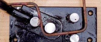
and back. The rear panel has two threaded holes. These holes will serve to secure the machine in a horizontal position when processing wood.
And fasteners to secure the stand in a vertical position. A single bolt is welded to provide grounding. The holes for the wires are not visible here, but they are in the drawings.
About the adjustable feet. By some chance, there were no standard legs from a refrigerator or washing machine, I’m just amazed. I had to make it from a bolt and an enlarged washer, the price was a couple of kopecks. But I had those things into which the legs are screwed, but tall nuts would fit perfectly in their place.
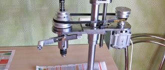
The drum is the one that will spin the cable. I took a creative approach to making this part. It works exactly the same, but is designed differently. Steel bars larger than 10mm in diameter are difficult to find in a home shed and my shed is no exception. Plus, I immediately resolved the issue of the removable handle. As an axis I used an M10 bolt with a short GOST thread. Cutting off the excess from it I got a smooth axle. The bolt head will serve as a kind of element for engaging the axle with the handle. The outer part of the drum will serve as a water pipe. If you do not have such a pipe in your metal waste, then you can replace it with a pipe purchased at the nearest plumbing store. To center the axle, we had to make bushings, so to speak, manually, without a lathe. To do this, I clamped two M10 nuts on the remaining bolt scrap (don’t throw away the scrap, it will come in handy later), inserted it into a drill and sharpened the entire structure using an electric sharpener. Since there are no threads on the bolt trim, the threads in the bushings also need to be drilled. The bolt head has a hole with an M5 thread for attaching the handle. It turned out pretty good.
Read also: Tool for soldering bumpers
In the picture below, I have already welded the bushings to the axle, the main thing is not to forget to put on one of the eyes first. There are holes in the outer race of the drum through which the race will be welded to the bushings. All dimensions and clearances are indicated in the drawings.
Carriage. There’s not much to tell here, we’ll assemble everything according to the drawings. Just one addition. In the original, the carriage is locked with one of the adjusting bolts. After all, they are adjustable, so as not to touch them, so after welding all the parts, I made an additional threaded hole specifically for the locking bolt. I made the threads for the adjusting bolts only with a rough tap, in order to prevent spontaneous unwinding.
View from the other side. Sorry about my welds, I cook as I can.
The handle is also a lever. After looking at the photo, don’t throw tomatoes. In my design, the lever is made from a 17-size open-end wrench. It had a broken cap, so I gave the short spanner a second life.
On the one hand, I welded a homemade washer from a strip onto the cap part of the key.
Next, an element that is not in the original design is the stop. This stop is attached to the top of the guide post and is used when securing the machine in a horizontal position. The holes for mounting to the stand are not made coaxially to minimize rotation of the stop.
Another new detail. I called it "table". Since there is no plane on my bed, I had to twist around. It is made from a piece of laminated chipboard, not the best option, but so far. With the help of screws I have the opportunity to set the working plane perpendicular to the stand.
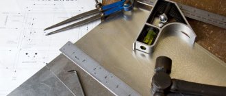
This is what it looks like. The photo also shows an auxiliary carriage on which a ruler and a tool for woodworking will be placed.
And here you can see the table adjustment element.
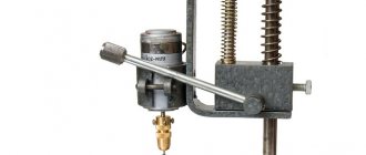
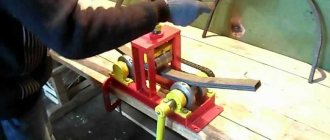
It's time to make a bracket for attaching the drill. And again the materials that I had were used. Clamp made of strip 25x4 mm, extension from pipe 30x30x2. This strip fits perfectly inside the pipe, making it easier to attach one to the other. And this rotation of the clamp ensures perfect alignment. The clamp is made by tapping a strip around a pipe with a diameter of 40 - 42 mm.
And brew it carefully. I was worried about the quality of these seams, since this is the weakest place in the entire structure.
Let's put the welder aside for a while and get to the drill. As I already said, I had been planning to make the machine for a whole year. During this time I acquired a drill, which I don’t mind. It was given to me as a non-working one. The wire was simply crushed inside and over time it burned out in this place. I corrected the wire, but the drill, apparently, is very tired and full of backlash. The first thing to replace was the cartridge and rolling bearings. The shank bushing was also broken.
To be honest, I would tear off the hands of these designers who added a ratchet function to a simple drill. There is no sense, the bearings are broken and the axial movement of the cartridge adds to all the delights. The most interesting thing, at least in this drill, is that the ratchet unit is the same size as the outer race of bearing No. 608. My attempts to knock the ratchet out of the silumin cage were unsuccessful; I had to cut off the teeth with a hacksaw and go to the market to look for a bronze bushing. And at the market they charged an absurd price for this sleeve, which I was very offended by and basically left with nothing. In place of the bronze gold bushing, the inner race from the same 608 bearing fits perfectly in size. One bad thing is that this is a one-time replacement; next time you will have to change the bushing along with the cartridge shaft. Let's see how long he lives. To eliminate the axial movement of the shaft, instead of a repelling spring, I installed a bushing made from a plumbing fitting, and placed a machined washer on the other side. The bearings have been replaced, the backlash has been eliminated, and the mechanisms have been lubricated.
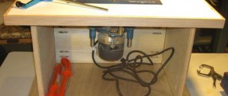
Attention, the faint of heart, please do not look at the next picture! Since this drill was specially reserved for the machine, I tried to make it so that it could only work in this machine. I cut the handle. From the barbarian... The start button was removed, the reverse lever remained in its original place, the cut was covered with a neat lid.
And what did I get in the end? I placed the button in the cavity of the frame, made a threaded hole in the front panel and tightened the adjusting screw there. Thus, I received a remote speed control unit. You tighten the screw, it gradually presses a button that changes the speed of the drill. Separately mounted a toggle switch for turning on the machine.
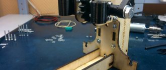
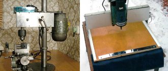
Below is the process of assembling the spindle bracket. I attached a guide from the printer to the chuck, which made it possible to relatively accurately align the axis of the tool perpendicular to the table.
Here is the welded bracket. I immediately made a hole in the table and bed. I cut a thread in the bed to screw in the center to hold the wooden workpiece during turning work. Then he began to prepare parts for the manufacture of a tool rest (Podruchnik is a stand for a cutting tool on a lathe).
And here he is ready. It has simplified functionality; there is no height adjustment. I have never worked as a woodturner in my life, or metal lathe either, I will learn and try.
And in principle, the machine is ready; almost the maximum load was chosen for the test. The first serious hole was made with a 13 mm drill in the front panel of the machine to install the toggle switch; let me remind you, the panel is made of a 4 mm thick strip. The result exceeded all expectations, without preliminary drilling and a minimum of effort, without even straining, I drilled a hole in a matter of seconds. I was glad, the state of euphoria passed and noble traces of young rust began to catch my eye. I was in a hurry to assemble everything and didn’t bother to paint it in detail. Now we have to take everything apart.
Read also: In what position is the circulation pump installed?
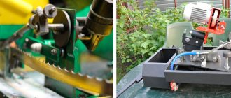
As always, I waited until it got colder to start painting. Therefore, I had to paint in the barn, it’s not a pleasant pleasure, paint on the street. I chose the color green, this association has been with me since childhood - if it’s a machine, then it’s green.
Painting the bed. I was too lazy to take out the wire, a collective farm is a collective farm.
The paint has dried and here is the result of the work:
On the other side:
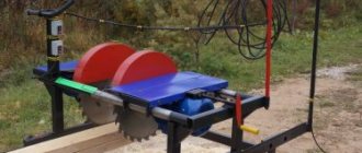
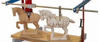
And in the lathe position:
Here are the promised drawings. I ask all norm inspectors and very smart people not to comment on the drawings, or even look at them :)) just a joke. Enjoy it for your health! I even drew up a specification according to which you can estimate the volume of materials needed. But I must warn you, do not blindly believe the drawings, double-check, I am not a robot and can sometimes make mistakes.
The result is a great tool. I cannot yet fully evaluate the turning option, since I only have a chisel instead of cutters. But as a drill there are a couple of “buts”:
- Try to make a frame like that of the author Zhelezjaka, the design will be simpler, lighter and smoother.
- One shoulder handle is terribly uncomfortable, it’s hard to explain why it’s inconvenient, but it’s uncomfortable. I will remake it into a three-armed one. In my version it’s simple, I unscrewed one and screwed the other. If you do it according to the original version, then pay attention to this.
- The handle is placed, as it were, behind the machine, which increases the required free space. In the future I will move it closer to the spindle using a chain drive.
- The front center (the toothed thing that rotates the wood piece) does a very poor job of holding the piece. The design needs to be changed.
And do not forget to use personal protective equipment when working. Do not violate safety requirements, no matter how stupid and ridiculous they may seem.
Every home craftsman has in his tool arsenal many different devices that allow him to bring his creative ideas to life. There are not only the usual sets of keys, screwdrivers, needle files and files here. A self-respecting specialist must have machine tools. This is a device for sharpening cutting tools, a small lathe for wood or metal, a milling machine or circular saw, and a welding machine. Even a novice home craftsman can make a drilling machine with his own hands.
Why is a machine more efficient than a drill?
As a rule, at home, if it is necessary to drill holes, a hand or electric drill is used. The use of these tools is justified only if there are no special requirements for the accuracy of the hole being drilled.
When trying to drill holes with a drill, the drill may move to the side, resulting in either a defect or a product of low quality. It is generally impossible to make a deep hole in a strictly vertical or strictly horizontal direction without a machine.
It is very difficult to drill in any material not a through hole, but a hole to a given depth (blind hole) using a drill, since this tool does not provide for the use of a ruler during drilling. A drilling machine can handle this task very easily .
When working with soft materials such as wood or plastic, the machine can be used to create milled holes or recesses. It is impossible to perform such operations with a drill.
Machine based on the steering rack of a passenger car
A steering rack for a car and a drill are quite massive products, so the frame should also be massive and, preferably, with the ability to attach the machine to a workbench. All elements are welded, since connections with bolts and screws may not be sufficient.
The frame and support post are welded from channels or other suitable rolled products, about 5 mm thick. The steering rack is secured to a stand, which should be 70–80 mm longer than the rack, through the eyes of the steering column.
To make the machine more convenient to use, the drill control is placed in a separate unit.
Assembly procedure for tabletop drilling machines:
- preparation of all elements;
- attaching the stand to the frame (check verticality!);
- assembly of the movement mechanism;
- fastening the mechanism to the rack;
- fastening the drill (check verticality!).
All fastenings must be made as securely as possible. It is advisable to join one-piece steel structures by welding. When using any kind of guides, you need to make sure that there is no lateral play during movement.
Advice! To fix the part in which the hole is drilled, the machine can be equipped with a vice.
You can also find ready-made stands for drills on sale. When purchasing, you need to pay attention to the weight of the structure and the size of the working surface. Lightweight (up to 3 kg) and inexpensive (up to 1.5 thousand rubles) racks are suitable for making holes in a thin plywood sheet.
Main nodes
Regardless of the complexity caused by the need to solve certain technical problems, each homemade drilling machine contains in its design the following main components:
- bed;
- electric motor;
- drill chuck;
- transmission mechanism;
- controls and measuring equipment.
The main structural element of any machine tool is the bed - a massive structural unit to which all other parts are attached. As a rule, a massive metal or wooden plate is used as a frame.
The chuck functions as a drill holder that will be used when drilling holes of various diameters.
An electric motor, powered from a household network, is designed to create torque and transmit it to the cartridge through a transmission mechanism.
The transmission mechanism allows you to reduce or increase the speed of rotation of the cartridge when moving the drive belt in it from one pair of pulleys to another. The pulley for the drilling machine can be taken from industrial equipment or made independently.
The controls are the on/off buttons for the electric motor, as well as a lever through which the rotating drill is driven into the workpiece.
The measuring equipment is a ruler that is mounted on a vertically moving part of the machine. In this case, the reference point is located on the stationary part, and the ruler moving downwards together with the drill indicates the depth of drilling the blind hole.
Drilling machine made of profile pipe and bearings
Square metal profile is one of the most popular materials for making a benchtop drill press.
There are a lot of options for homemade structures made from corrugated steel pipes. Let's consider the most optimal, in our opinion, tabletop drill stand for a home workshop.
Necessary materials:
- profile pipe;
- threaded rod;
- bolts with nuts;
- metal corner;
- bearings;
- spring;
- channel;
- pieces of metal strip.
First of all, we make a stand. You will need a piece of thick metal (plate) and two pieces of corrugated pipe (20x20 mm and 25x25 mm). The length of each piece is 40 cm.
We drill mounting holes in the metal plate, and then weld two profiles to it.
We make a carriage from four pieces of square corrugated pipe 15x15 mm, as well as bolts with nuts and bearings.
A homemade carriage is placed on a stand made from a larger profile. We place a slider on the second rack measuring 20x20 mm.
We drill a hole in it. Then you need to weld the extended coupling. We strengthen the joint with metal gussets.
To fix the homemade slide at the desired height, use a wing nut.
Next, a lever made from a steel angle is attached to the slider and carriage. A handle made of a profile pipe must be welded to the lever.
A piece of channel is used as the base of the machine. We drill holes in it and fasten the metal plate with the stand using bolts.
In the end, all that remains is to make a mount for the drill. We attach it to the carriage. We install an electric drill. A spring is used to automatically return the carriage to its original position.
Manufacturing methods
Equipment can be manufactured from a wide variety of raw components. The created machine may not be universal, but narrow-profile, for example, for drilling holes in printed circuit boards. Based on this, the stages of manufacturing the machine may vary slightly. Below, examples are used to describe the process of manufacturing devices of various designs and purposes in a home laboratory.
Mini drill
Many radio amateurs either already have, or really want to have in their workshop a machine for drilling holes in circuit boards. Why buy a store-bought Dremel when you can make your own mini drill press? The tabletop machine differs from its traditional analogues in its miniature dimensions; accordingly, all its parts are also small in size. As a rule, the weight of such devices does not exceed 5 kg, the frame is a platform of 300x300 mm, the height is about 250 mm.
To assemble miniature machine tools you will need the following components:
- supporting frame;
- stabilizing frame device;
- a bar designed to move the working head;
- shock absorption device;
- electric motor mounting bracket;
- electric motor;
- electric motor power supply;
- adapters and collets.
The assembly of a miniature machine for drilling holes in printed circuit boards must be performed in the following sequence:
Read also: How to charge alkaline batteries
- Installation of the frame. As a frame, you can use a platform made of textolite 300x300 mm, the thickness of which is 20−50 mm. If necessary, holes should be drilled in the lower part of the frame and the legs should be secured in them.
- Installation of the holder frame and travel bar. Having drilled holes in the right places, these parts should be securely attached to the frame.
- Installation of the holder frame with shock absorber. These parts are also secured to the plane of the frame.
- Installing the drill head movement handle on the frame holder and connecting it to the shock absorber.
- Electric motor installation.
- Attaching a collet device or a special miniature chuck for small-diameter drills to the electric motor shaft.
- Making a power supply and connecting it to an electric motor.
- Installing the drill into the chuck and performing test drilling.
Homemade mini machine for radio amateurs is ready for use.
Drill machine
Craftsmen who design and assemble furniture at home cannot do without special machine tools. It is not difficult to assemble a simple drilling and additive machine with your own hands, but one that perfectly copes with the functions assigned to it, even in a home workshop.
This can be done without purchasing any specific or expensive components. To create such equipment, you will need an industrial-made manual or electric drill, which must be mounted on a self-made frame.
First of all, you should prepare the necessary tools and materials:
- electric or hand drill;
- sheet of plywood 10-12 mm thick, dimensions 300x500 mm;
- wooden blocks;
- wood screws or self-tapping screws.
The machine assembly procedure consists of the following operations:
- First of all, you should create a working drawing of the machine indicating the dimensions of its main structural elements.
- Cut out all the structural elements of the future machine from the available wood.
- Create a coordinate table for a machine with your own hands. To do this, a sheet of plywood measuring 300x500 mm must be marked with longitudinal and transverse lines in increments of 10 mm.
- It is necessary to attach a wooden block, carefully sanded with sandpaper, to a horizontally placed coordinate table or frame, which will act as a vertical guide.
- Next, you need to make a carriage from a sheet of plywood 10-12 mm thick, to which an electric or hand drill will be attached. For this purpose, you need to assemble a device on the front panel that allows you to securely fix the drill, and on the back side of the sheet you need to attach a square made of bars, which will be put on the vertical guide. The inner surfaces of this square must also be carefully sanded.
- A wooden lever for moving the carriage up and down should be attached to the top of the guide. You need to screw the rod to the carriage, and then fasten the lever and the rod with a hinge joint.
- At the final stage, it is necessary to wax all rubbing wooden surfaces.
After connecting the electric drill plug to the AC mains, the homemade machine is ready for use for its intended purpose.
There are many options. You can make a good machine from a photo enlarger. In this case, the old equipment already has a ready-made frame and vertical guide. All that remains is to secure the carriage with the electric drill.
Options and techniques for creating a good drill press
In industrial plants and workshops with large volumes of repetitive procedures associated with the processing of materials, simple designs are not enough.
This is ensured by the fact that during drilling operations, materials with different densities and hardness are machined.
To assemble a high-quality and productive machine for drilling holes, you can choose different options, the most common of which include the following:
- a drilling machine made from a professional drill with a reliable and stable stand;
- equipment with an asynchronous motor and the ability to install drills of different diameters.
Vertical and horizontal drilling machines that differ in design, made by hand, allow you to work with different materials.
These can include plastic, metal and wooden parts, the processing of which requires compliance with the parameters of accuracy and quality of drilling activities.
Using both options, you can significantly save money without spending it on purchasing an expensive factory-made machine that will not be used very often.