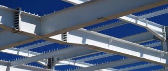
Metal I-beams
In addition to the widespread construction of multi-storey buildings with a large number of apartments, the construction of private houses has become widespread, not only small one-story ones, but also quite large ones, with two or more floors, sometimes with an attic above or a habitable attic. For such houses the frame method is no longer suitable; The material is often brick or reinforced concrete instead of wood. The construction of large private houses must be carried out according to all the rules of construction science, since errors in the design or implementation of the project can lead to undesirable consequences.
If the house under construction is a permanent building - made of concrete, brick, cinder block, then it is advisable to use reinforced concrete slabs for ceilings, interfloor and attic floors. The most suitable type of frame that can withstand the weight of such floors is a frame whose element is a metal I-beam.
It is this type of rolled product, installed vertically with its wall, that has the greatest load-bearing capacity. Naturally, the foundation and walls of the house must be strong enough to withstand an additional weight of 0.5 to 1 ton - this is how much metal, depending on the number of beams and profile number, may be needed for the ceiling.
To avoid unnecessary costs and excess weight of the ceiling frame, as well as to prevent collapse or significant deflection of the beams, it is necessary to calculate their parameters in advance and, based on the calculation results, select the required rental. The calculation comes down to calculating the following values: the required moment of resistance and the minimum moment of inertia of the beam section, and based on the latter - the maximum relative deflection.
Note The calculation is carried out according to two characteristics - strength and stiffness. Based on the obtained values of the moment of resistance and moment of inertia in the GOST tables, the required rental number is found.
Initial data for calculations
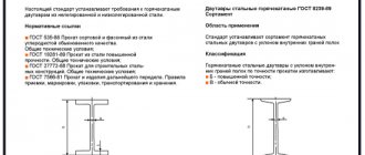
For the frame of ceilings of small-sized private houses, an I-beam of 10 - 20 numbers is usually used. The characteristics of these profiles are given in GOST 8239-72 - their linear dimensions, cross-sectional areas, maximum vertical moments of resistance Wy and minimum moments of inertia Jy.
It is necessary to know the type of slabs that will rest on the beam frame, as well as the dimensions of the load-bearing perimeter of the house. You can use hollow reinforced concrete slabs PK-12-10-8 (1180 x 990 mm, weight 380 kg), and take the dimensions of the house to be 4.5 x 6 m. The beams are laid along the short wall; The laying step for this size of slabs is 1000 mm (the joints of the slabs coincide with the longitudinal axes of the beams, with a minimum gap of 1 cm). This will be required to calculate the distributed load, and based on it - the linear load on the beam; the weight of the beam itself is small compared to the distributed load, and it can be neglected when calculating the linear load.
The distributed load with this type of slab will be equal to 325 kgf/m2. To this we must add the load of possible partitions on the upper side of the ceiling (75 kgf / m2) and a possible temporary load (200 kgf / m2). As a result, the load distributed over the area:
Q = 325 + 75 + 200 = 600 kgf/m2,
and linear load
q = Q * p = 600 kgf / m = 6 kgf / cm.
This value is used in further calculations.
Numbers, letters and GOSTs
According to the production method, the channel can be bent or hot-rolled. It is easy to distinguish them even for a non-specialist - a hot-rolled channel has a clearly defined edge, while a bent channel it will be somewhat rounded. Other features of various types of channel are determined by their markings.
In particular, the letters A, B and C in relation to batches of hot-rolled channels will indicate that the rolling was carried out with high (A), increased (B) or normal accuracy (C).
The channel number indicates the height of its section, expressed in centimeters.
The width of the profile corresponds to the width of the shelf and can range from 32 to 115 mm. The marking of a channel, for example 10P, reflects its height and type of profile. The height of the channel section is generally the main parameter in its marking. The channel number is its height in centimeters, and the letters adjacent to it indicate that the channel cross-section can be:
1) with a slope of edges (series U and C), where U is the slope, and C or Sb are special series. 2) with parallel edges (P, E and L series), where E means economical series, and L means light. Letters C (for example - 18С, 20С, etc.) can be found in products intended for the automotive industry or for the construction of railway cars (GOST 5267.1-90). Sometimes there are also exotic types of channels. For example, GOST 21026-75 determines the parameters of channels with a bent flange (they are used in the production of trolleys for mines and mines).
The most popular channel sizes
The most popular among consumers are channels with numbers from 8 to 20. Their geometric parameters in categories P (that is, with parallel edges) and series Y (with a slope of internal edges) are the same, the difference is observed only in the radii of curvature and the angles of inclination of the shelves.
It is mainly used to strengthen structures inside domestic and industrial buildings. In its production, semi-quiet (3PS) and mild (3SP) carbon steels are used, which are characterized by excellent weldability.
widely used in mechanical engineering, machine tool manufacturing and other areas of industry. It is also successfully used in the construction of bridges, walls and load-bearing supports in the construction of industrial buildings.
is very similar to the “eight” channel, but has higher strength characteristics and load-bearing capacity, which makes it possible to reduce the metal consumption of structures erected with its participation.
- one of the most popular types of channels. used in building structures for rigid reinforcement of load-bearing parts, giving metal structures special strength and rigidity. Channel 14 comes in standard and increased accuracy.
Channel 20 acts as a load-bearing element when reinforcing bridges, when reinforcing floors (including complex ones) of multi-storey buildings, and in roof purlins.
Due to its high performance qualities, the “twenty” is often used in structures with high loads - both dynamic and static.
There are also non-standard applications of channels. A perforated (that is, “holey”) channel allows, for example, the installation of metal structures without welding, which significantly reduces installation time. For perforation, channels with high shelf heights and wide distances between them are best suited. Such products are designated by the letters ШП - “Perforated Channel” and are most often used in the construction of temporary structures (for example, scaffolding) or warehouse racks.
To create such structures, channels with small numbers are better suited, since the weight of the rack (and therefore the channel from which it is assembled) should not be too large.
In interior decoration, channels are used as a “security” frame when laying high-voltage electrical wires.
Sometimes channels are also used as a guiding load-lifting device, including as ramps for strollers and carts.
In general, the use of channels can be varied, but still their main purpose is to strengthen structures and the ability to withstand long-term loads.
Deflection calculation
The bending moment for each beam is calculated based on the magnitude of the linear load q, the pitch of the beams p and the length of the overlapped span L. Since the beams are laid along the short side, then L = 4.5 m = 450 cm (of course, the beams themselves are longer - about 5 m, since they rest on the walls, but it is the inner edges of the walls that serve as hinged supports for them).
The required value of the moment, in this case:
My = (q * L2) / 8 = 6 * 4502 / 8 = 151875 kgf * cm.
The maximum moment of resistance of a beam section can be calculated by dividing the bending moment by the design resistance of steel - for example, grade C235, equal to 2150 kgf / cm2:
Wy = 151875 / 2150 = 70.6 cm3.
This obtained value must be compared with the value of the moment of resistance of the section of the I-beam. From the GOST 8239-72 table it can be seen that the calculated indicator approximately corresponds (with a margin) to the moment of resistance for profile 14 (81.7 cm3). Therefore, this rental number will satisfy the requirements for the strength of the beams.
Requirements
All requirements for metal beams are clearly outlined in GOSTs and SNiPs. The main requirements are :
- Durability . Depending on the type of material used in the manufacture of the product, strength indicators may differ, but they must correspond to the values specified in regulatory documents.
- Operating period . Metal structures, according to GOST, must last at least 80 years.
- Corrosion resistance . Finished elements must be additionally treated with compounds that prevent the formation of corrosion.
Stiffness calculation
The rigidity of beams is characterized by the maximum deflection value for given initial parameters. In the case of a distributed load, the deflection is calculated using the formula:
f = 5 * q * L4 / (384 * E * Jy), where
- q – linear load on the beam;
- L – span length;
- E – elastic modulus of the material, for steel C235 equal to 2.1 * 106 kgf/cm2;
- Jy is the minimum moment of inertia for a given profile.
For the previously accepted initial data, taking into account the fact that, based on the strength calculation, the most suitable profile turned out to be No. 14, for which Jy, according to the GOST table values, is equal to 572 cm4, we can obtain:
f = 2.6 cm,
and to a relative extent, taking into account the fact that the span length is 450 cm - 1/172. This exceeds the maximum permissible deflection, taken equal to 1/250.
Therefore, the calculation has to be repeated and the deflection calculated for another rental number. For No. 16, whose moment of inertia is 873 cm4, the absolute deflection is 1.74 cm, and the relative deflection is 1/256, which is acceptable.
Conventions in channel markings - how to understand them?
And since the main purpose of the channel is to withstand loads, from its markings it is first necessary to find out the parameters that will allow this load to be calculated, namely, the composition of the steel, its strength, rolling quality, and so on.
What can you learn from the labeling?
For example, before us is a package of hot-rolled channels, on which it is written: 30P-V GOST 8240-97/St3sp4-1 GOST 535-88
This means that we have a 30P channel - that is, with parallel edges and a section height of 30 cm. The letter B indicates the usual rolling accuracy B, made of steel St3, fourth category, first group.
The same channel, but only made of steel 09G2S with increased rolling precision will receive the designation 30P-B GOST 8240-97/345 GOST 19281-89
, in which 345 will mean the strength of steel corresponding to grade 09G2S.
But in the marking A 300x80x6 B GOST 8278-83/2-St3sp GOST 11474-76
the letter A will indicate high accuracy of profiling of a steel blank (strips) from the second category of steel St3sp, from which a bent equal-flange channel with dimensions of 300x80x6 is made (where 300 mm is the height of the section of the product, 80 mm is the width of the shelves, and 6 mm is the thickness of the shelves and walls)
Calculation results
So, for a room measuring 4.5 x 6 m, the ceiling frame made of reinforced concrete slabs PK-12-10-8 with a distributed load of 600 kgf/m2 can be constructed from I-beams of profile No. 16, steel grade C235, located along the short side in increments 1 m. You can calculate that for such a building you will need 7 such beams 5 m long, and, knowing the mass and price per linear meter, calculate the total mass of the beam frame and its cost.
So, for the example given, the total number of linear meters is 35; the weight of the beam frame made of profile No. 16 is 525 kg.
Description and types of channels
Channel – U-shaped shaped profile
Channel is a type of shaped profile . This product has a U-shaped configuration and consists of a wall and shelves. The latter can be parallel to each other, with an inward slope, of different lengths. The configuration and dimensions of the product determine its purpose.
There are hot-rolled and bent channels.
Hot rolled – produced by hot rolling. The steel strip is heated to a temperature of +1000°C and fed to the mill. The rollers give the workpiece a U-shape. In such a beam, the shelves are exactly parallel to each other. The corners are hard. Such structures are most often used for reinforcement, as they are able to withstand very high load-bearing loads.
There are 5 types of hot rolled channel :
- P – element with parallel shelves;
- U - the outer corners of the edges reach 90 degrees, and inside they create a slope due to different thicknesses. The slope does not exceed 10%;
- E - due to the rounding of parallel shelves, the product, in general, weighs less, with the same strength characteristics;
- L – lightweight version with thinner walls and edges;
- C is a special profile with a configuration determined by the needs of the industrial sector.
The bent profile is distinguished by rounded corners inside and outside. It is made using the cold method. The steel strip is bent on rollers without preheating. This technology is more expensive, but the resulting channel is much stronger and more durable. It can be used for tension frames. There are 4 options:
- B - with edges inclined inward;
- P – with parallel shelves;
- L – option of smaller thickness and weight with other standard sizes;
- S – special.
The bent profile carries less load-bearing load, but is much more resistant to torsion, compression and tension.
Examples of calculated resistance
To calculate an I-beam, a value such as design resistance (Ry) may be required. It depends on the grade of steel from which the beam is made. For example, here are the ready-made values:
- C 235 - 230 MPa;
- C 345 - 335 MPa;
- From 255 - 250 MPa.
The elastic modulus is taken as one value, equal to steel: E = 200,000 MPa. The calculation of the load of an I-beam is carried out on the basis of load-bearing capacity calculations. To this figure add 30% for strength (this applies only to welded profiles).
Taking steel grade into account when determining strength
When calculating strength, the grade of steel is taken into account. For difficult climatic conditions, the I-beam is made of non-brittle steel. It is better to choose the most durable brands. Here it should be taken into account that a product of higher strength may have smaller dimensions and, therefore, the permissible pressure will be less.
That is why a competent calculation of strength is performed in several different versions, then the parameters are compared. To determine the strength, it is necessary to decompose the applied force along the axes and determine the maximum moments around these axes.