To produce compressed air, any air compressor uses atmospheric air as a feed stream. When the pneumatic station is turned on, the air flow enters the chamber of the screw block through the suction valve.
Thanks to this device, the pneumatic station is able to function, since air from the surrounding space enters the compression chamber, where the main process for which any type of air compressor is used takes place.
Compressor valves - what are they?
An air compressor is a unit whose operating principle is based on compressing and supplying air to pneumatic equipment under the required pressure. Such installations are an indispensable element both in everyday life and in industry, being an autonomously functioning technical unit or being included in more complex electrical appliances (for example, climate control or refrigeration equipment). The schematic diagram of any compressor includes a working chamber and a valve system. And since these devices, like any other mechanisms, can break down, you need to know how they are designed, what types of valves there are, how to choose them correctly or make them yourself. More on all this in the material below.
Repair kits for intake valves
We can supply you with the following repair kits:
- intake valve repair kits;
- control units for intake valves;
- pneumatic cylinders for intake valves;
- solenoid valves.
| Product name | Installation location |
| 510.0163 | intake valve R20E |
| 510.0363 | intake valve R40E |
| 510.0564 | intake valve R90E |
| 510.0360 | intake valve RH100E |
| 510.5760 | intake valve RH250E |
| 510.0160 | intake valve RB60E |
| 510.0360 | intake valve RB80E |
| 510.5160 | intake valve RB115E |
| 510.7160 | intake valve RB115P |
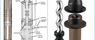
Any screw compressor includes a loading system for pumping atmospheric air into the operating unit. Controlling the operating modes of the compressor unit, monitoring the output of the unit, and regulating the injection of air into the screw assembly is provided by an important part called the inlet valve. It keeps the compressed air from reversing, ensures consistent pressure reduction during breaks in machine operation and ensures normal functioning of the compressor module.
Types and principles of operation of valve mechanisms
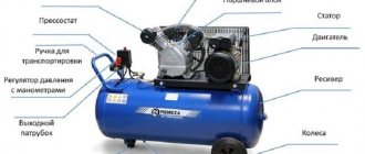
Currently, the most common types of compressors are screw and piston units. At the same time, screw compressors, for example, those produced by the Belarusian plant REMEZA, are widely used in various industries, and piston compressors are used in everyday life. The latter can be found both in garages of car enthusiasts (compressors such as SO-7B, Forte VFL-50, etc.) and in life support systems for fish in aquariums (Resun compressors, etc.), as well as in household pneumatic tools.
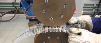
Piston compressors are characterized by a simple design and a relatively small number of parts and components. There are many different designs of such compressor units, equipped with special plate valves that regulate the process of suction and injection of air during operation . Depending on the purpose of compressor units (their performance, power and operating pressure), three types of valve mechanisms can be found:
- disk - their plates can be made of both metal and high-quality polymers, including reinforced ones;
- ring - parts for them are made of cast iron, steel or non-ferrous metals (the choice of material is determined by the type of compressor);
- disc valves - plates for this type of valve are made of polymer materials and are used in compressors operating with contaminated media.
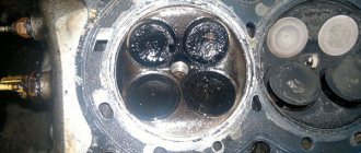
Inlet and exhaust valves
Inlet and outlet valve assemblies play such a role in the operation of compressor equipment.
- The movement of the piston to bottom dead center causes air to be drawn in through the open suction valve.
- When the bottom point is reached, the piston begins to move in the opposite direction. At the same time, the suction valve closes, and the air in the sealed chamber begins to decrease in volume under the influence of piston pressure.
- When approaching top dead center, the discharge valve opens and air compressed under high pressure begins to flow into the receiver.
- Having displaced the air from the chamber, the piston again begins to move to the bottom dead center, and the working cycle is repeated.
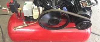
Unloader and safety valves
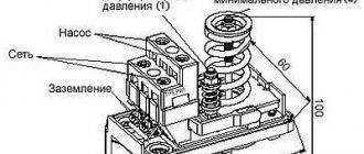
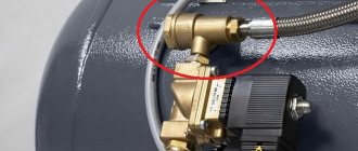
Thus, the compressor pumps air into the receiver cycle by cycle until the specified pressure value is reached. This process is monitored by a special pressure switch (pressostat), which controls the operation of the electric motor by turning it on and off depending on the degree of air compression. As a rule, the pressure switch also includes a starting unloading valve. A pressure switch is connected between the output of the compressor head and the check valve (return valve), which is connected to the receiver and holds the compressed air there.
Important! The safety valve is responsible for relieving air pressure. Its functions include: ensuring a smooth start of the compressor and preventing the return of compressed air to the compression chamber after the engine is turned off.
The necessary pneumatic equipment is connected directly to the receiver, which can be additionally equipped with various devices (separators, filters, pressure equalizers, etc.).
VMC intake valves
Trading House AERO offers inlet valves for screw compressors manufactured by the Italian company VMC from a warehouse in Mytishchi. Correspondence table between old and new intake valve models
| power, kWt | New model | Old model |
| 4/5,5 | RH30 3/4″ | RH5 |
| 11 | RH30 1″ | RH10 |
| 18,5 | RH38 | RH25 |
| 22 | RH38 | RH25 RH40 |
| 22 | RH60 | RH25 RH40 |
| 30 | RH60 | R40 |
| 18,5/22/30/37 | RB60 | R40 |
| 37 | RB60 | R90 |
| 45/55 | RB80 | R90 |
| 75 | RB80 | RH100 |
| 90 | RB90 | RH180 |
| RH250 | ||
| 100/132/160 | RB115 | RH350 |
| 250/215/350 | RB200 | RH600 |
Specifications
| Model | Nominal diameter, mm | Compressor power, kW | Productivity, m3/min | Execution | Weight, kg |
| RH30 | 20 or 30 | 4-11 | 0,2-1,8 | E, NR | 0,3 |
| RH38 | 38 | 7,5-22 | 1,2-3,5 | E, NR | 0,8 |
| RH60 | 62 | 22-37 | 3-7 | E, NR, P, PM | 1,5 |
| RB60 | 6 (60) | 22-37 | 3,5-7 | PM, E, NR | 2,2 |
| RB80 | 8 (80) | 45-75 | 6-12,2 | 3,0 | |
| RB90 | 9 (90) | 90 | 7-15 | 6,5 | |
| RB115 | 11,5 (115) | 110-160 | 15-27 | 10,0 | |
| RB125 | 12,5 (125) | 132-200 | 17-32 | 11,0 | |
| RB140 | 14,0 (140) | 180-250 | 20-40 | 12,3 | |
| RB200 | 2*14,0 (140) | 250-350 |
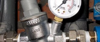
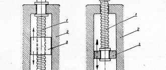
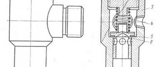
Check valve
A check valve (return valve) is a device that allows compressed air to flow in only one direction . Structurally, it is assembled (see figure) in a metal case (item 3), inside of which the following are located:
- internal shutter (item 6), blocking the inlet;
- a spring (pos. 4) pressing the rubber ring (pos. 5) to the bolt seat;
- inlet fitting (pos. 7);
- plug (item 1) with a sealing gasket made of cardboard (item 2) (the plug makes it possible to disassemble the return for repair or maintenance).
On a note! The check valve has a branch for connecting it to the receiver and a small branch for connecting a pressure switch.
Operating principle
The reverse action valve works as follows. Passing through the outlet valve of the piston cylinder, the compressed air enters the return pipe through the inlet fitting (pos. 7). Having reached a certain pressure, the air lifts the internal shutter (pos. 6) and passes through the cavity in the housing (pos. 3) into the storage tank of the receiver. When the compressor is turned off, the spring (item 4) returns the internal shutter to its place, blocking the path of air from the receiver back into the piston cylinder.
Features of the functioning of the suction valve
The suction valve has some design features. This is not only a restriction of air access to the pneumatic unit. For some diesel-powered mobile compressors, the inlet valve may also provide air flow to cool the engine. In this case, the compressor design provides an additional valve, which sucks air from the housing into the screw block.
In most models, the suction valves are equipped with air filters, making it possible to operate compressor stations in dusty environments. With a properly functioning valve, the compressor can be manually moved to idle mode and back to load mode. This is a kind of damper that can be in two positions - open or closed.
If the suction valve is faulty, problems are inevitable. It may not provide a sufficient flow of atmospheric air, and this will cause a decrease in the performance of the pneumatic station. To prevent this from happening, it is advisable to pay attention to the valve during every compressor maintenance.
Range
The catalog presents positions of suction valves intended for installation in air compressors from leading manufacturers of compressor equipment. The operation of the units depends on how efficiently the air flow intended for compression is supplied.
Here are devices that are installed in front of the compressor unit, as well as in other places in compressor structures where air supply is needed. All devices have been tested and have a certificate of compliance with the operating requirements and ensuring the functionality of pneumatic system equipment.
Safety valve
The relief valve (another name is safety) valve serves for emergency release of pressure and is the final device that protects the pneumatic equipment connected to the compressor from damage.
Attention! It is not recommended to operate the compressor without a safety valve.
Experts also include the following types of relief valve:
- bypass valve;
- unloading valve.
Despite minor design differences, their operating principle is identical to a safety valve.
What to pay attention to
Before purchasing a valve, first take into account such a circumstance as the intensity of the existing air flow. In other systems it may be liquid or gas. This circumstance directly affects the startup and error-free operation of the installed valve.
In addition, you need to take into account that the performance coefficients of the air purifying unit are interrelated with the power data of the pumping device, be it a pump or a fan. When choosing a valve, take into account the temperature conditions in the room and the environment in which the device will be installed. The level of environmental pollution is also significant. For example, a unit of the “butterfly” variety, when exposed to a stream of cold air, begins to significantly slow down. This can lead to poor fusion between the duct and the mechanism as a whole. The cost of the valve can fluctuate insignificantly and directly depends on the technical parameters and the company that developed the mechanism .
Discharge valves
Discharge valves perform the following functions:
- in systems with open nozzles, they prevent the penetration of gases from the working cylinder into the cavity of the high-pressure pump;
- disconnecting the fuel line and the cavity of the high pressure pump during the suction code of the pump plunger, thereby ensuring improved filling;
- contribute to obtaining a sharp end of injection and reducing injector leakage;
- ensure the creation of residual pressure in the fuel injection line in systems with closed injectors, which in some cases contributes to better control of the injection process and more strict maintenance of injection phases;
- make it possible to reduce the residual pressure (valve with relief belt) in the fuel injection line and thus eliminate fluctuations in it after the end of injection;
- make it possible to adjust the feed characteristic, bringing it closer to the desired one.
Valves are classified according to their design:
- mushroom-shaped
- cylindrical
- lamellar
- combined
- double discharge valves
Rice. Designs of discharge valves: a-d - mushroom-shaped, e, f - cylindrical, 1 - nut; 2 - limiter; 3 - spring; 4 - valve; 6 - pump housing; 7 - suction belt; 7 - guide; 8 - valve body, gasket