Principle of operation
The operating principle of the automation unit is simple. The device is mounted on a pipe communicating with the receiver. The spring-diaphragm pressure switch sensor for the compressor continuously measures the pressure. As soon as it drops below the set value, the sensor rod, under the action of a spring, closes the contacts of the compressor relay and the electric motor is connected, pumping air into the tank. After reaching the set pressure, it presses the rod and opens the contacts, turning off the engine. Adjustment of these values is available to the user. In addition, when the operating pressure limit is reached, the safety valve included in the device is activated, releasing excess air from the compressor into the atmosphere.
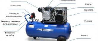
Purpose
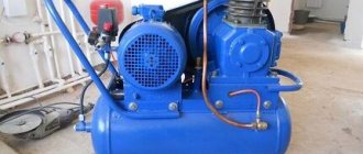
The function of air compressors is to produce a stream of air with a certain pressure; it must be stable and uniform. It should also be possible to change the parameters of this jet. Each compressor has a reservoir (cylinder) for air. It must have the required pressure. When it drops, turn on the engine to replenish the air supply. If there is excessive pressure, the air supply should be stopped to prevent the container from bursting. This process is controlled by a pressure switch.
Pressure switch device RDM-5
When it functions correctly, the engine is preserved, it is protected from frequent switching on and off, and the operation of the system is uniform and stable. The container membrane is connected to the pressure switch. By moving, she can turn the relay on and off.
Principle of operation
Taking into account the amount of pressure in the system, the relay serves to open and close the voltage circuit; if the pressure is insufficient, it starts the compressor and turns it off when the parameter rises to a predetermined level. This is a normally closed loop operating principle for motor control.
The opposite principle of operation is also encountered, when the relay turns off the electric motor at minimum pressure in the circuit, and turns it on at maximum. This is a normally open loop circuit.
The working system consists of springs of different levels of rigidity that respond to changes in pressure. During operation, the deformation forces of springs and compressed air pressure are compared. When the pressure changes, the spring mechanism is activated and the relay closes or opens the electrical circuit.
Accessories
The air compressor relay may contain the following components:
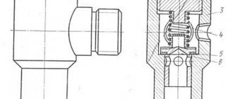
- Unloading valve. It is located between the compression chamber and the compressor check valve. When the engine stops, this component is activated and removes excess pressure from the piston block. When the engine starts, the pressure generated closes the valve, making it easier to start the unit. Some unloader valves have delayed activation. When starting the engine, it assists the engine by remaining open until the system reaches a predetermined value. During this time, the engine reaches maximum speed.
- Mechanical switch. Serves to enable and disable automation. The switch usually has two positions. When the mode is turned on, the automation is activated, the compressor is connected to the network and turned off, taking into account the specified pressure parameters in the system. In the OFF position, no power is supplied to the drive.
Detailed description of the pressure switch for the compressor (video)
Device
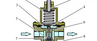
All components of the compressor pressure switch are assembled in a compact unit, covered with a plastic or metal case. The product includes:
- Inlet and outlet pipes.
- The sensitive element is a spring and a membrane.
- Stock. Connected to the membrane and placed inside the spring coils.
- Contact Group.
- Adjustment screws.
- Unloading and safety valve.
- Mechanical switch.
The elasticity of the spring, and, consequently, the sensitivity of the sensor, depends on the ambient temperature; most devices are designed to operate in the temperature range from -5 to +70 °C.
The unloading unit is designed to release air from the compressor cylinders after it stops. Thereby:
- its subsequent launch is facilitated;
- wear of piston group parts is reduced;
- the service life of the entire unit is extended.
When the unloading valve is activated in the silence that follows after the compressor stops, a sharp characteristic sound is clearly audible.
The mechanical switch serves for the initial start and final stop of the compressor. It has two positions: “On” and “Off”. “On” activates automatic operation systems. It transfers further control of the compressor to the pressure switch. The “Disabled” position prevents spontaneous starting of the motor when the pressure in the receiver drops below the set value.
The safety valve allows you to release excess pressure into the atmosphere in the event of a relay failure and avoid compressor breakdown in this case.
A thermal relay can serve as additional protection for the compressor motor. It is included in the automation unit; it disconnects the motor windings from the supply voltage in the event of an increase in current strength, indicating an overload of the motor.
Setting up an air compressor comes down to setting the operating pressure with an adjusting screw. The pressure regulator has values marked on it. Pressure can be controlled more accurately using a pressure gauge.
Purpose
The function of air compressors is to produce a stream of air with a certain pressure; it must be stable and uniform. It should also be possible to change the parameters of this jet. Each compressor has a reservoir (cylinder) for air. It must have the required pressure. When it drops, turn on the engine to replenish the air supply. If there is excessive pressure, the air supply should be stopped to prevent the container from bursting. This process is controlled by a pressure switch.
Pressure switch device RDM-5
When it functions correctly, the engine is preserved, it is protected from frequent switching on and off, and the operation of the system is uniform and stable. The container membrane is connected to the pressure switch. By moving, she can turn the relay on and off.
Principle of operation
Taking into account the amount of pressure in the system, the relay serves to open and close the voltage circuit; if the pressure is insufficient, it starts the compressor and turns it off when the parameter rises to a predetermined level. This is a normally closed loop operating principle for motor control.
The opposite principle of operation is also encountered, when the relay turns off the electric motor at minimum pressure in the circuit, and turns it on at maximum. This is a normally open loop circuit.
The working system consists of springs of different levels of rigidity that respond to changes in pressure. During operation, the deformation forces of springs and compressed air pressure are compared. When the pressure changes, the spring mechanism is activated and the relay closes or opens the electrical circuit.
Accessories
The air compressor relay may contain the following components:
- Unloading valve. It is located between the compression chamber and the compressor check valve. When the engine stops, this component is activated and removes excess pressure from the piston block. When the engine starts, the pressure generated closes the valve, making it easier to start the unit. Some unloader valves have delayed activation. When starting the engine, it assists the engine by remaining open until the system reaches a predetermined value. During this time, the engine reaches maximum speed.
- Mechanical switch. Serves to enable and disable automation. The switch usually has two positions. When the mode is turned on, the automation is activated, the compressor is connected to the network and turned off, taking into account the specified pressure parameters in the system. In the OFF position, no power is supplied to the drive.
Detailed description of the pressure switch for the compressor (video)
Types of pressure switch devices
There are two main versions of the device available. The pneumatic-mechanical part is identical; the difference is determined by the method of closing the contacts when the rod moves:
- Normally closed (NC). used for direct control of low and medium power motor circuits.
- Normally open (NO). The movement of the rod closes the contacts when the maximum pressure is reached. The reverse movement opens them as it decreases. The contacts are used to control a more powerful relay that starts and stops the electric motor. The circuit turns out to be more complex, but the load on the pressure switch contacts is reduced and the service life increases.
When replacing a relay, you must carefully check that its type matches the electrical circuit of the compressor. his type.
Installation of relays and auxiliary elements
In addition to basic components, devices are often equipped with additional devices that increase ease of use or expand the functionality of the device.
They are installed on flange connections, most often 1/4”
The pressure switch is connected to the compressor as follows:
- Screw the inlet pipe to the tank pipe.
- Connect a pressure gauge, unloading and safety valves to the flanges of the device.
- Close unused holes with plugs.
- Connect the electrical connector of the relay to the electric motor.
Low-power electric motors are connected directly; more powerful ones will require the use of a starter. The design of the pressure switch must match the engine power.
Adjustment and commissioning process
The device is configured and adjusted at the manufacturer's factory. Typical values are 2.8 atm. for the upper limit and 1.4 for the lower limit. However, sometimes situations arise in which it is necessary to adjust the device yourself:
- Setting up after partial or complete repair.
- Specific requirements of consumer devices.
- Installing a relay that was not originally designed to work with this compressor.
Before you begin adjustment, you should carefully study the parameters of all mating devices according to their data sheets. Passport data must correspond to the numbers embossed or engraved on a plate attached to the body of the unit.
The main indicator is the maximum pressure for which the compressor is designed. The value at which the pressure switch will operate should be 0.4-0.5 atm less than this maximum. In real operating conditions of the device, taking into account voltage instability, losses in seals, and the degree of wear of the piston group, this pressure may not be achieved. Then the pressure switch will not turn off the motor, the compressor will work continuously, overheat and wear out.
Having decided on the parameter values, you can begin making adjustments. To do this you need:
- Remove the casing.
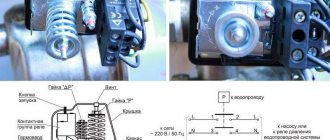
- Two nuts will become available - a larger one and a smaller one. These are the regulatory bodies. Arrows are engraved on the body nearby, showing the direction of rotation to increase and decrease the parameter, respectively.
- The large nut sets the value at which the electric motor turns off. When rotated clockwise, the value increases, in the opposite direction it decreases. It is indicated by the P (Pressure) icon.
- The smaller nut sets the difference in engine start pressure compared to the shutdown value. It is designated ΔР.
Before you start setting up, you should fill the tank at least 2/3 full. The sequence of actions is as follows:
- Disconnect the unit from the network.
- Adjust the P and ΔP values by rotating the adjusting nuts.
- The set values should be monitored using a pressure gauge.
A number of manufacturers place adjustment controls on the outside of the device. This increases the convenience of adjustment, but at the same time increases the risk of changing the settings by accidental touch.
DIY air pressure switch for compressor (price+video)
The use of an air pneumatic relay allows you to automate the filling of the compressor receiver with compressed gas. The owner or operator of equipment with a pressure switch does not need to monitor the process, trying to fix the limit parameters. As a result, engine breakdown is prevented and the operating life of the equipment is increased. Significant results, right?
If you are planning to purchase a pressure switch for your compressor, then you have come to the right place. Here you will find a vast amount of extremely useful information about the principles of operation of the device, its configuration and connection methods.
The author of the article describes in detail the existing types of pneumatic relays. Provides options for connecting to household and industrial networks with extremely clear diagrams. Discusses typical breakdowns and ways to prevent them. The information and useful tips presented to you are complemented by graphic, photo and video applications.
- Installation of relays and auxiliary elements
- Adjustment and commissioning process
- Possible malfunctions of the device
- Troubleshooting methods
- Conclusions and useful video on the topic
Operating principle of a pressure switch
The name of the relay is determined by its purpose - controlling a piston compressor to maintain the required atmospheric pressure in the receiver. It is rarely found on a screw type device responsible for compressing and supplying air.
I take into account the magnitude of the pressing force in pneumatic automation; the device acts on the voltage line, closing or opening it. Thus, insufficient pressure in the compressor starts the motor, and when the required level is reached, it turns it off.
This standard operating principle, based on connecting a normal closed loop to a circuit, is used to control the motor.
The design of all ejectors contains a cylinder containing air at a certain pressure. Reducing it requires turning on the engine to replenish the supply. If the situation is the opposite and an excess is detected, the supply is stopped so that the container does not burst. These processes are controlled by a pressure switch
Modifications with the opposite operating algorithm are also presented: when reaching minimum values in the compression circuit, the pressure switch turns off the electric motor, and at maximum values it activates. Here the system operates in a normally open loop.
The operating system is made up of spring mechanisms with varying degrees of rigidity, reproducing the response to fluctuations in the air pressure unit.
During operation, the indicators formed as a result of the elastic force of tension or compression of the springs and the pressure of the atmosphere pressed by the device are compared.
Any changes automatically activate the action of the spiral and the relay unit connects or disconnects the electricity supply line.
However, it is worth considering that the design of the review model does not provide for regulatory influence. Exceptional impact on the engine. In this case, the user has the opportunity to set a peak value, upon reaching which the spring will fire.
Adjusting the compressor pressure
As mentioned above, after creating a certain level of air compression in the receiver, the pressure switch turns off the unit’s engine. Conversely, when the pressure drops to the switching limit, the relay starts the engine again.
Important! By default, relays, both single-phase devices and units operating from a 380 V network, already have factory settings. The difference between the lower and upper engine start threshold does not exceed 2 bar. It is not recommended for the user to change this value.
But often situations that arise force you to change the factory settings of the pressure switch and adjust the pressure in the compressor at your discretion. You can only change the lower switching threshold, since after changing the upper switching threshold upward, the air will be released by the safety valve.
Pressure adjustment in the compressor is carried out as follows.
- Turn on the unit and record the pressure gauge readings at which the engine turns on and off.
- Be sure to disconnect the device from the power supply and remove the cover from the pressure switch.
- After removing the cover, you will see 2 bolts with springs. The large bolt is often designated by the letter “P” with the signs “-” and “+” and is responsible for the upper pressure, upon reaching which the device will be turned off. To increase the level of air compression, turn the regulator towards the “+” sign, and to decrease it, turn towards the “-” sign. First, it is recommended to make half a turn with the screw in the desired direction, then turn on the compressor and check the degree of pressure increase or decrease using a pressure gauge. Record at what indicators of the device the engine will turn off.
- Using a small screw you can adjust the difference between the on and off thresholds. As mentioned above, it is not recommended that this interval exceed 2 bars. The longer the interval, the less often the device’s engine will start. In addition, the pressure drop in the system will be significant. Setting the on-off threshold difference is done in the same way as setting the upper on-off threshold.
In addition, you need to configure the gearbox if it is installed in the system. It is necessary to set the compression level on the gearbox to a level that corresponds to the operating pressure of the pneumatic tool or equipment connected to the system.
Possible malfunctions of the device
The device is characterized by its simple design and high reliability. However, they are also subject to malfunctions and breakdowns. A number of minor difficulties can be easily corrected with your own hands:
- Air leakage from the device when the pump is turned on. Identified by a characteristic whistle and the feeling of a sharp cold draft near the body. Most often the cause is a broken start valve. To repair, the gasket must be replaced.
- Frequent starting of the motor. The cause may be loose adjustment screws. It is necessary to carry out the procedure for adjusting the on and off threshold values using the pressure gauge and, if necessary, restore the passport values.
In case of serious problems, experienced technicians recommend not to bother with repairs and subsequent adjustments, but to immediately replace the entire device.
Troubleshooting methods
More complex work will be required if the compressor does not turn on. This can happen if the relay contacts wear out and melt from sparks that occur when the electric current is interrupted. Two methods are possible:
- In case of slight wear of the contact groups, clean the areas with a file or sandpaper. Care must be taken not to bend the slats. This will extend the service life by several weeks.
- Replace the contact groups with new ones from the repair kit for this model.
To repair contact groups, the following operations should be performed:
- Bleed the air from the tank and disconnect the unit from the network.
- Remove the relay from the compressor.
- Remove the casing.
- Disconnect the wires going to the contacts.
- Using a screwdriver, pry the contact terminal out of the mount and carefully drill out the melted areas.
- The wire is replaced with copper wire of the appropriate cross-section. It should fit into the hole with minimal clearance. The wire is passed into the hole and pressed tightly with pliers.
- After repairing all melted contacts, reassemble the device in the reverse order.
It makes sense to spend time on such repairs only if branded spare parts are unavailable for replacement.
Connection diagram
The connection diagram for the pressure switch depends on the type of electric motor. Single-phase ones are controlled by relays designed for 220 V with two contact groups. For three-phase electric motors, a 380 V device is installed, with three contact groups, each connecting its own phase. The use of single-phase switches for three-phase loads is unacceptable, since one of the phases remains permanently connected to the winding.
Flange connections
A number of manufacturers install additional flange connectors on their products. Most often there are two or three of them, the standard size is ¼ “. Through them, components such as a safety valve, pressure gauge, etc. are connected.
Installing a pressure switch
For installation, you must perform the following operations:
- Connect the relay to the receiver pipe.
- Connect the pressure gauge, safety and relief valves through the flange connectors.
- Place plugs in the remaining unoccupied connectors.
- Connect the wires from the engine to the electrical connector of the device.
- Make adjustments.
The last point should be considered in more detail.
Relay adjustment
Important! The adjustment is carried out with at least 2/3 of the tank filled and the power turned off.
The manufacturer supplies devices that have been tested and adjusted to standard values. If the parameters of a given compressor or the characteristics of consumer devices require you to configure the relay to other values, you should do the following:
- Remove the device cover.
- Two wrench heads will become visible.
- The big one controls the shutdown pressure and is designated by the letter P (Pressure).
- The small one controls the pressure difference at which the motor turns on. It is designated by the letters ΔP.
- The arrows indicate the direction of rotation for increasing values (+) and decreasing values (-).
- Control the pressure using the pressure gauge and set the required values.
Next, you should reassemble the device in reverse order. The compressor is ready for operation.
Structure of pneumatic relay symbols
The marking of the air pressure switch indicates the entire optional set of the device, design features, including information about the factory settings for the pressure differential.
Condor's production models offer a wide range of pressure control equipment. The MDR series is aimed at using ejectors of various powers
Let us examine the designations in more detail using the example of devices for air ejectors RDK – (*) (****) – (*)/(*):
- RDK – series of relays for compressors;
- (*) – number of threaded ports: 1 – one port with 1/4”NPT internal thread; 4 – four connectors;
- (****) – type of housing design: T10P – version 10 with a “lever” switch; T10K – “button” switch; T18P – execution 18 with a “switch” switch; T19P – 19 s;
- (*) – factory settings of the threshold response: 1 – 4…6 bar; 2 – 6…8 bar; 3 – 8…10 bar;
- (*) – diameter of the unloading valve: the absence of a symbol means a standardized parameter of 6 mm; 6.5 mm – 6.5 mm.
The difference between the minimum and maximum pressure thresholds is set by the manufacturer and, as a rule, has a value of 2 bar.
However, it is also possible to manually adjust the range of two values – maximum and minimum, but only downward.
The specifics of setting up pressure switches for pumping stations are outlined in the following article, the contents of which we recommend that you familiarize yourself with.