6R13F3 milling machine is equipped with an NC-220 CNC system, three HA-075 feed drives and is designed for multi-operation processing of parts of complex configurations made of steel, cast iron, non-ferrous and light metals, as well as other materials in automatic mode according to a pre-compiled technological program. Along with milling operations, the machines can perform precision drilling, boring, countersinking and reaming of holes. Scope of application: small-scale and mass production.
Distinctive characteristics of the machine
The slider moves up and down, adjustable along the Z coordinate. It is impossible to set positions and operate the tracking mode on the machine console; it only has setting functions and has a high mass.
The console is always clamped during processing, which increases the final processed accuracy. The machine has a feed system, servo regulating, with electric motors with direct current, having a high torque. The use of servo-controlled adjustable drives with DC electric motors ensures fast table movement speeds of up to 4.8 m/minutes and eliminates part deviations during competition when the feed system is turned off at an arbitrary point. The design of the machine includes a centralized lubrication system for the guide part of the machine. The machine uses an electromechanical clamping device, providing a stable clamping force of 2000 kg. For individual devices there is prefabricated wiring with connectors. The quality of the processed surface after processing it on this machine is Rz = 20 microns.
6Р13Ф3-37 machine characteristics
Buy this machine without intermediaries:
Specifications:
Machines model 6р13ф3-37 are designed for multi-operation processing of parts of complex configurations made of steel, cast iron, non-ferrous and light metals, as well as other materials. Along with milling operations, the machines can perform precision drilling, boring, countersinking and reaming of holes
Dimensions of the working surface of the table, mm 400x1600 Maximum movement of the table (longitudinal), mm: 1000 Maximum movement of the table (transverse), mm: 400 Maximum movement of the table (vertical), mm: 420 Distance from the axis of the horizontal (end of the vertical) spindle to the working surface of the table , mm 70-500 Main spindle speed limits, min-1: 31.5-1600 Feed limit (longitudinal), mm/min: 12.5-1600 Feed limit (transverse), mm/min: 12.5-1600 Feed limit (vertical), mm/min: 4.1-530 Main movement electric motor power, kW: 11 Feed drive electric motor power, kW: 3 Weight of workpieces with fixture, kg 300 Dimensions, mm 2570x2252x2430 Weight, kg 4300
Buy this machine without intermediaries:
mashinform.ru
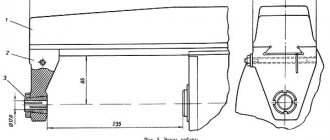
Connecting dimensions of CNC milling machine 6Р13Ф3
Fig. 2. Connecting dimensions of CNC milling machine 6р13ф3-37
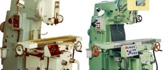
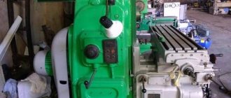
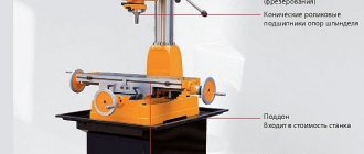
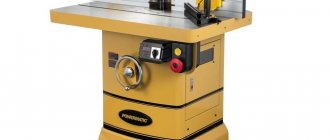
General view of the 6R13F3 milling machine
The appearance of the machine resembles classic milling machines in appearance, the only thing that really catches your eye is the electric motor located on the table to ensure longitudinal feed.
Fig 3. Photo of milling machine 6р13ф3-37
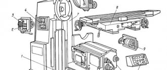
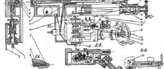
6Р13Ф3 Arrangement of components of a CNC console milling machine
Fig. 4. Location of the components of the 6р13ф3-37 CNC milling machine
Fig 5. Location of the components of the 6р13ф3-37 CNC milling machine
- Bed - 6Р13Ф3-37.10; 2. Gearbox - 6Р13Ф3-37.25; 3. Console - 6Р13Ф3-37.61; 4. Electrical box - 6Р13Ф3-37.068; 5. Table and slide - 6Р13Ф3-37.70; 6. Electrical equipment - 6Р13Ф3-37.80; 9. Spindle head - 6Р13Ф3-01.38; 10. Gearbox - 6Р13Ф3-01.32; 11. Gearbox - 6Р13Ф3.50; 12. Guide protection - 6Р13Ф3.74; 14. Cooling - 6Р13Ф3.90; 15. Fencing - 6Р13Ф3.91; 17. Protective device - 6M13P.91
Location of controls for a CNC machine model 6Р13Ф3
Fig 6. Location of controls for milling machine 6р13ф3-37
List of machine controls 6Р13Ф3 and their purpose
- Ram travel limiting cams
- Tool release button
- Tool Clamp Button
- Cooling pump switch
- Toggle switch for turning on the Z coordinate
- Toggle switch for turning on the Y coordinate
- X coordinate switch
- Technological stop toggle switch
- Toggle switch for manual and automatic operating modes
- Feed rate selector switch
- Manual longitudinal movement of the table
- Feed switch
- Toggle switch for setting coordinates to zero position
- Start Program button
- Button for stepwise movement of nodes
- Spindle start button
- Console Up button
- Stop spindle button
- Console Down button
- Z-coordinate zeroing cams
- X-coordinate zeroing cams
- Console clamp handle on frame
- Longitudinal stroke limiting cams
- All stop button
- Speed indicator
- Spindle Jog button
- Gear shift knob
- Console stroke limiting cams
- Manual vertical movement of the console
- Handle for raising and lowering the fence
- Y-coordinate zeroing cams
- Table cross travel limiting cams
- All stop button
- Manual lateral movement of the table
Kinematic diagram of a 6R13F3 CNC milling machine
Fig 7. Kinematic diagram of a CNC milling machine 6р13ф3-37
Machine operation with electromechanical tool clamping
The machine is equipped with an electromechanical tool clamping device, which is controlled in accordance with the required algorithm: press button 3 (see Fig. 6) “tool clamp”; by pressing button 17 “Start spindle”, start the spindle.
If the tool is wrung out, then you should: use button 19 to “cut off” the spindle and check that the spindle stops rotating; press out the tool using button 2 “Tool release” and hold until the milling tool holder leaves the spindle for a length of about 15-20 millimeters. Otherwise, there is a possibility that the splined roller will be pulled out of the rod, which will lead to breakdown. Then you should screw the thread at the end of this roller into the thread of the rod, pressing the rod towards the top to clamp the tool. The type and possibility of installing a cutter depends on their size and the type of cutter. The tool is first secured separately from the machine when using ramrods that are replaceable. The mandrel has standard dimensions, namely the outer cone 7:24 and the inner one according to the dimensions of the Morse cone No. 4. If the tool has the following Morse cone dimensions No. 2,3,5, then installation occurs due to replaceable bushings.
In general, tool clamping is not very different from a great many similar CNC machines, just as tool changing is not something special.
The machine does not have a tool magazine, which requires the allocation of space for storing tools directly in the mandrels (in mass production, each tool is tied to its own “zero” coordinates and stored in niches and cabinets), this only applies to the tool used, since the spare one is stored in a container and There is no need to tie it down (there are physically not enough mandrels). This also obliges you to enter data on the bindings of each tool used on various media (you can remember it, but with a shifting work schedule of the enterprise, conflicts and incidents may arise).
Electrical equipment of the 6R13F3 machine. General information
The electrical equipment is located in the control station built into the machine, and it is equipped with control software of the “N33-2M” type. At its core, a control station is a cabinet full of electronics, namely switching devices and safety systems. The control station also powers the electronics from a 380 V “socket” with a frequency of 50 Hz. The voltage indicator should not fluctuate more than 15% with an error of 10% from the same 380 V network.
Each power circuit uses different voltages:
- power circuit - three-phase, alternating current 380 V, frequency 50 Hz;
- control circuit - AC 110 V, 50 Hz;
- local lighting circuit - alternating 24 V, 50 Hz;
- control circuit - 24 V DC;
- electrodynamic braking circuit - 55 V DC;
- power supply for electric motors - 48 V DC.
Current is supplied when the toggle switch on the box door is switched.
List of electric drives installed on the machine: electric drive of the main movement; carried out from an asynchronous motor type 4А132S4У3, 7.5 kW, 1450 rpm, 380 V (A02-5I-4, 7.5 kW, 1450 rpm, 220/380 V); electric drive for adjustment movement of the console; carried out from an asynchronous motor type 4A90LA, 2.2 kW, 1500 rpm, 380 V; electric drive for tool clamping; carried out from an asynchronous motor type 4ААС56В4У3, 0.18 kW, 1500 rpm, 380 V; electric drive of the cooling pump; performed by an asynchronous motor XA14-22M (0.12 kW; 2800 rpm; 380 V; lubrication electric motor type AOL-21-4, 0.27 kW, 1500 rpm; 380 V; longitudinal feed electric drive (X coordinate) is carried out from a DC electric motor type PBB-112L 2.2 kW 1000 rpm, 110 V. Information about the position of the drives is transmitted by a rotating transformer type BTM-1V.
Description of the design of the CNC milling machine 6Р13Ф3
The structure includes: bed, machine gearbox, gearbox, machine spindle head, table and slide, console
The bed is the main supporting structure on which I mount various mechanisms and components of the machine. The rigidity of the structure is obtained due to the massive base and a large number of stiffening ribs. The housing is equipped with vertical guides on the front for moving the console and a ruler for measuring installation movement. The console travel is limited by limit switches from the left niche located in the frame. There is a technical window for access to the oil supply and speed control system, which is located in the upper right part of the housing. Also on the left side of the frame there is a gearbox for selecting the required spindle speed. The frame body is equipped with an oil reservoir. The base for the frame is most often a concrete base, to which it is attached with bolts.
The gearbox transmits movement to the output link, that is, the spindle. Lubrication is carried out not by spraying oil itself, but by using a pump with a plunger system. It provides 18 speeds without the need to sequentially pass through intermediate stages. The speeds are switched using this sequence of actions: handle 28 (Fig. 6) is lowered down until the spike of the handle comes out of the groove securing it and pushed away until it “clicks.” By rotating the dial, position 26, Figure 6, set the required feed according to the numbers on the panel. Moreover, when the dial makes a characteristic click, the dial is fixed at the desired level. By pressing the “Push” button, position 27, Figure 6, return the handle to its original position by turning it with smooth movements. The gearbox is lubricated from the same pump as the gearbox.
The slide, gearbox, and slide with spindle are the three main components of the spindle head. Centering of the slide is carried out due to the annular groove located in the “throat” of the machine. The slide guides are rectangular in type along which the spindle moves along with the slide itself. The gearbox, consisting of a pair of bevel wheels of three cylindrical ones, is designed to transmit rotational motion to the spindle assembly. The slider moves (together with the spindle assembly) using motors with high torque, using a gearbox and pairs of wheels described above for a screw-nut type transmission. Manual movement of the spindle assembly is possible using a hexagon
For movement along the X and Y coordinates, the table and slide are units that allow longitudinal and transverse movement. An engine of the PBV112LGUZ type drives the drive to move along the X coordinate through a single-stage gearbox (in which the wheel diameters differ by exactly two times) and a screw-nut transmission. The lead screw device serves to move the table in the longitudinal direction and rotates in ball bearings installed in the bracket and gearbox housing, on the left and right sides, respectively.
The bracket mount for fixing the nut is mounted in the table. The gearbox has a transformer for moving the table in the longitudinal direction, which is a feedback sensor of the BTM-1V type. The console is equipped with a drive that provides movement to move the table along the Y coordinate. A ball screw for transverse movement is also mounted in the console body. Manual movement is possible due to the output of the hexagon i.e. element numbered 35 in Figure 6. Also in the design of the machine, wedges are used to select the gap in the table guides.
The console is a basic unit; it combines drives for movement along the X coordinate (vertical) and for transverse movements. Installation movements are carried out along vertical guides that have a “dovetail” in their profile. Horizontal movements are made along the console guides with a rectangular profile for the transverse direction of the table-slide assembly along the Y coordinate. Also for transverse movement there is a gearbox mounted in the console in which the additional ratio is I = 1:2. Motor type PBV122LGZU has a high torque and serves to move the table in the transverse direction through a gearbox and a screw-nut type transmission. Cylindrical helical gears are made of a prefabricated type, which allows you to select the side clearance to reduce vibrations in the meshing of the teeth. The VTM-1B type transformer is mounted in a gearbox and is rotating. A 4A90LA asynchronous type motor for up-down movement is installed on the right side of the housing and is used for installation movements. A worm pair and a screw gear are used to carry out movements. Lubrication of moving components and guides is required, and for this purpose an oil tank and a VT II-IIA type lubrication pump are provided, which is powered by an AOL-21-4 type engine. The horizontal guides of the console are protected from the front by protection with a telescopic operating principle, and at the back an apron is attached through the rear end of the slide to the frame.
Machine mod. 6р13ф3
The machine is designed for processing workpieces of complex profiles made of steel, cast iron, difficult-to-cut steels and non-ferrous metals in single and batch production. The tools used are end, face, corner, spherical and shaped cutters, drills, and countersinks. Machine accuracy class N.
2.1. Technical characteristics of the machine
| Size of the working surface of the table (width length) | 4001600mm |
| Number of spindle speeds | 18 |
| Spindle speed limits | 40 – 2000 rpm |
| Limits of table and slider working feeds | 10 – 2000 mm/min |
| Speed of rapid movement of table and slider | 4800 mm/min |
| Largest diameter of end mill | 125 mm |
| Largest end mill diameter | 40 mm |
| Largest drill diameter | 30 mm |
| Overall dimensions of the machine (length width height) | 320024652670mm |
2.2. CNC device
The machine uses contour type CNC – NZZ-2M. The software carrier is eight-track punched tape, ISO code. Geometric information is specified in increments. The interpolator is linear-circular. The number of controlled coordinates is 3, the number of simultaneously controlled coordinates for linear interpolation is 3, for circular interpolation – 2. The discreteness of reading along the coordinate axes X', Y', Z is 0.01 mm. Spatial processing is achieved by a combination of table movement along two coordinates (X' and Y') and vertical movement of the slide with the cutting tool (Z coordinate). It is possible to work in preset mode with the program being entered into the CNC device directly by the operator using the keyboard.
2.3. Layout, main components and movements in the machine
The base of the machine (Fig. 1) is frame A, which has a rigid structure due to the developed base and a large number of ribs. Console B moves along the vertical guides of the frame body (installation movement). The table-slide mechanism D moves along the horizontal (rectangular profile) guides of the console in the transverse direction (feed along the Y' axis), and the table moves along the slide guides in the longitudinal direction (feed along the X' axis). The transverse and vertical feed drives are mounted in the console body, and the longitudinal feed drive is mounted in the slide body. The cutter receives its main movement from gearbox B. A drive for vertical movements of the slider along the Z axis is installed in the spindle head D.
Rice. 1. General view of the machine mod. 6Р13Ф3
2.4. Machine kinematics
The main movement. Spindle VIII receives rotation from an asynchronous electric motor M1 (N = 7.5 kW, n = 1450 rpm) through a gearbox with three movable blocks of gears B1, B2, BZ and gears z = 39–39, z = 42–41–42 in the spindle head. The block switching mechanism provides 18 rotation speeds and allows you to select the required rotation speed without sequentially passing through intermediate stages. Kinematic chain equation for minimum spindle speed
.
Rice. 2. Kinematic diagram of the 6R13F3 machine
The tool in the mandrel is secured outside the machine using replaceable cleaning rods. The mandrel has an outer taper of 50 and an inner Morse taper of No. 4.
To fasten tools with Morse tapers No. 2 and 3, replaceable bushings are used. The tool is clamped by an electromechanical device. The bearings and gears of the gearbox are lubricated by a plunger pump located inside the gearbox.
Serving movements. The vertical feed of the slider with the spindle mounted in it is carried out from a high-torque motor M2 (M = 13 N m, n = 1000 rpm) through a gear pair z = 44–44 and a screw-nut transmission VII with a pitch P = 5 mm. Manual movement of the slider is provided. A feedback sensor is installed on shaft XI - a transformer of the VTM-1V type.
Transverse feed of the slide is carried out from a high-torque motor M4 (M = 13 N m, n = 1000 rpm), through a backlash-free gearbox z = 22–52–44 and a rolling screw nut XVII with a pitch P = 10 mm. The gap in the helical cylindrical wheels 1, 3 and 5 of the gearbox is eliminated by grinding the half rings 2 and 4 installed between the wheels 3 and 5.
The longitudinal feed of the table comes from a high-torque electric motor MZ (see Fig. 2) through a backlash-free gearbox z = 26–52 and a rolling screw XIII with a pitch P = 10 mm. Feedback sensors are installed in the gearboxes of longitudinal and transverse movements - transformers of the VTM-1V type. The gap in the table and slide guides is selected using wedges. The gap in the rolling screw-nut gears is eliminated by turning both nuts in one direction by the required number of teeth.
Auxiliary movements. Special hexagonal pins can be used to perform manual movements along the X' and Y' coordinates. The installation vertical feed of the console is carried out from an M5 electric motor (N = 2.2 kW, n = 1500 rpm) through a worm pair z = 2–40 and a lead screw XIX.
studfiles.net
Factors leading to the choice of a 6R13F3 machine
The first factor for choosing a machine is its standard size, which indicates the maximum dimensions of the workpiece, and in milling machines this is the size of the work table (or, for example, in lathes, the height of the centers). This machine has a working table size of 400x1600.
The second factor is the total cost of the machine (purchase and installation). The total cost of the machine is about 520 thousand rubles. and varies depending on the CNC device model.
It is also required, when choosing a machine, to pay attention to the possibility of automatic tool change, but this machine does not have this function. The accuracy of the machine, according to the classification, is high.
The machine can be equipped with CNC systems that are the easiest to learn, but not for use since it has a small number of cycles and has a greater bias towards the use of conventional G codes in 3rd coordinates.
From the above we can conclude that the machine is suitable for medium-scale production because there is no automatic tool change, but it has a CNC system that allows you to automate the processing of one setup (which is not rational to overpay for in small-scale production).
Full list of characteristics of the machine 6Р13Ф3-37
| Accuracy class according to GOST 8-82 | N |
| Basic machine parameters | |
| Dimensions of the working surface of the table (length x width), mm | 400 x 1600 |
| Maximum load on the table (center), kg | 300 |
| Number of T-slots Dimensions of T-slots | 3 |
| Maximum longitudinal movement of the table (X), mm | 1000 |
| Maximum lateral movement of the table (Y), mm | 400 |
| Maximum vertical installation movement of the table, mm | 420 |
| Distance from the spindle axis to the vertical guides of the bed (overhang), mm | 500 |
| Minimum distance from the rear edge of the table to the bed guides, mm | 100 |
| Distance from the end of the spindle to the working surface of the table, mm | |
| Maximum vertical movement of the slider (Z), mm | 250 |
| Working feed limits. Longitudinal, transverse, vertical, mm/min | 3..4800 |
| Speed of rapid movement of the table and slider, mm/min | 4800 |
| The smallest and largest distance from the end of the spindle to the table mm | 70…490 |
| Feed per impulse, mm | 0,01 |
| Positioning accuracy along the X axis, mm | 0,065 |
| Positioning accuracy along the Y, Z axis, mm | 0,040 |
| Largest drilling diameter, mm | 30 |
| The largest diameter of the end mill, mm | 40 |
| Largest diameter of end mill, mm | 125 |
| Spindle | |
| Number of spindles | 1 |
| Spindle speed, rpm | 40…2000 |
| Number of spindle speeds | 18 |
| Maximum torque, kgf.m | 62,8 |
| Spindle end | GOST 836-72, 7:24 |
| CNC system | |
| CNC type | N33-2M |
| Dimensioning method | In increments |
| Types of interpolation | Linear Circular |
| Number of simultaneously controlled coordinates for linear / circular interpolation | 3/2 |
| Electrical equipment | |
| Number of electric motors on the machine | 8 |
| Main motion drive electric motor, kW (rpm) | 7,5 (1450) |
| Electric feed drives along the X, Y, Z axes, kW | 2,2 |
| Electric drive for adjustment movement of the console, kW | 2,2 |
| Electric drive for tool clamping, kW | 0,18 |
| Electric drive of the cooling pump, kW | 0,12 |
| Electric pump motor for smearing, kW | 0,27 |
| Total power of electric motors, kW | 16,87 |
| Machine dimensions | |
| Machine dimensions, mm | 3450 x 3970 x 2965 |
| Machine weight, kg | 4450 |
Specifications
The machine can process cast iron and steel structures of varying complexity. Many people recommend using it in small production. The device occupies an area measuring 3.45x3.97 meters. The height of the structure is 2.96 meters and the weight is 4,450 kilograms. Operation is controlled by automated control.
The software provides milling of the product according to the following parameters:
- moves the slider with the cutter from top to bottom and vice versa;
- moves the slide in which the workpiece is secured, left and right.
The equipment is equipped with high-torque motors, which allow the table to be transported quite quickly (approximately 4.80 m/min). Also, this feed design serves as a guarantee of quality during milling finishing work on a metal part, even if one of the drives fails.
In the design of the device, the developers designed a special mechanism for clamping the device, which operates on an electrical-mechanical principle. The mechanism can withstand clamping forces of up to 2,000 kilograms. The total power of all motors is 16.87 kW, and the moving power of the console is 2.20 kW.
In particular, the power is distributed between the following elements:
- cooling pump;
- axial feed;
- lubricant;
- main drive;
- clamp element.
With the help of the electrical wiring with which this device is equipped, it can be used in a place where there is no access to an electrical outlet. Note that the wiring is equipped with connectors for plugs.
The main technical characteristics of the 6R13F3 vertical milling machine include:
- maximum section size: 12.5 centimeters for an end mill and 4.0 centimeters for an end mill;
- number of T-slots: 3 pieces;
- maximum drilling section size: 3.0 centimeters;
- table dimensions: 40.0 centimeters - width and 160.0 centimeters - length;
- load on the working area of the equipment up to 300.0 kilograms;
- feed per single pulse: 0.01 millimeters;
- maximum table movement: 40.0 centimeters - in the horizontal direction, 100.0 centimeters - in the vertical direction and 42.0 centimeters in the installation (vertical) direction;
- length of the connector between the vertical guide of the frame and the spindle axis: 50.0 centimeters;
- working surface movement speed: 4.80 meters per minute (speed adjustable to 0.3 centimeters per minute);
Conclusion
This machine is both a good teaching aid for learning the basics of programming CNC machines, and a good choice for those just starting to automate the processing process due to its low cost (it can be purchased second-hand in the Avito online store) and ease of learning personnel. Even if the machine does not allow achieving the highest levels of automation, it can be an excellent transitional link for production, only increasing the production capacity and the number of products produced. Also, the machine from the 3rd stage of development of CNC machines and in terms of maintenance of the machine itself is not whimsical, but this is due to the fact that the third stage marked the appearance of electrical equipment with microprocessors, but not the integration of this equipment specifically into the production of machine tools (the appearance of those very “cabinets” connected to machines), what happens to the equipment of the 4th stage. This is precisely what expands the machine’s capabilities for use in production. The kinematics, which are not sensitive to strong loads, allow it to be used even for roughing (roughing) work, and the ease of repair allows you to use even old machines with the same high accuracy as stated in the passport.