Safety regulations
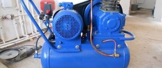
Compressor units of various operating principles and purposes are widely used on construction sites and in production.
Compressors can be permanently installed on concrete foundations or mobile, that is, mounted on a chassis. Regular use of compressor equipment is permissible subject to a number of conditions:
- The compressor must be equipped with automatic devices that prevent the permissible operating limit from being exceeded.
- There is a relief valve designed to quickly relieve excess pressure.
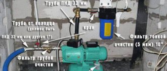
- This equipment must have filtration devices installed at the inlet and outlet, which ensure the purity of the air sent for processing to the compressor and create an obstacle to its entry into the room.
- The presence of installed pressure gauges provides control over the pressure parameters created by the compressor.
- An oil separating filter must be installed between the compressor unit and the receiver.
- In addition, air that contains toxic or harmful substances must not be supplied to the compressor stop.
Installed equipment must be subject to appropriate supervision and maintenance. It must be remembered that maintenance and routine maintenance must be carried out by trained personnel. The equipment that is under the supplier's warranty must be serviced by specialists from the appropriate service centers.
In particular, when washing compressor components and parts, only those liquids and compositions recommended by the manufacturer of this equipment should be used. Containers for storing compressed air must be equipped with safety valves, a drain valve, and a pressure gauge. In accordance with the requirements of the operational documentation, these tanks (receivers) must undergo routine maintenance and testing. Their results should be recorded in the maintenance log.
When organizing the operation of compressor and related equipment, it is necessary to use guidelines and other regulatory documents published by control bodies, for example, Rostechnadzor.
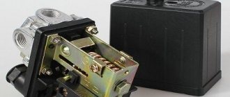
About the switch
The pressure switch for the compressor has a hole closed by a special valve. It opens in order to provide conditions for the removal of air from the compressor after the equipment is turned off. During subsequent starts, there will be no residual air in the tubes, this will prevent the permissible pressure parameters from increasing above the maximum levels.
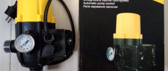
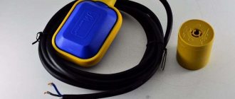
The pressure switch is responsible for closing or opening contacts, starting or stopping the engine. You can purchase a relay at any online store or regular point of sale that distributes equipment, tools for work and home. Be sure to read reviews first; if you have questions about the choice or operation of equipment, ask them to specialists and consultants.
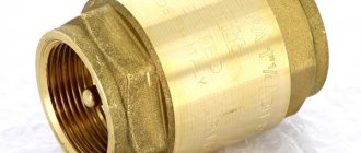
Check valve
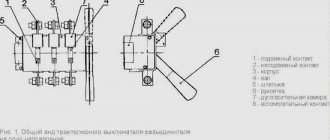
A check valve (return valve) is a device that allows compressed air to flow in only one direction. Structurally, it is assembled (see figure) in a metal case (item 3), inside of which the following are located:
- internal shutter (item 6), blocking the inlet;
- a spring (pos. 4) pressing the rubber ring (pos. 5) to the bolt seat;
- inlet fitting (pos. 7);
- plug (item 1) with a sealing gasket made of cardboard (item 2) (the plug makes it possible to disassemble the return for repair or maintenance).
On a note! The check valve has a branch for connecting it to the receiver and a small branch for connecting a pressure switch.
Operating principle
The reverse action valve works as follows. Passing through the outlet valve of the piston cylinder, the compressed air enters the return pipe through the inlet fitting (pos. 7). Having reached a certain pressure, the air lifts the internal shutter (pos. 6) and passes through the cavity in the housing (pos. 3) into the storage tank of the receiver. When the compressor is turned off, the spring (item 4) returns the internal shutter to its place, blocking the path of air from the receiver back into the piston cylinder.
Varieties
On the domestic market you can find compressors with returns made of three different materials: aluminum, plastic and brass. At the same time, the aluminum part differs from its analogues in its high reliability and durability. It is built inside the air duct that connects the piston cylinder to the receiver, and is capable of operating under high temperature conditions (up to 200°C). Whereas a plastic return line is installed in budget models operating at a low temperature of the working environment. As for valves made of brass, they are widely used. Such return valves are quite reliable and perfectly maintain their performance characteristics in cases where the air temperature during compression does not exceed 140°C.
Recommendations for selection
If the compressor return valve fails, it is not difficult to replace it with a similar one
However, before you buy a new valve, you need to pay special attention to the diameter of the threads cut on the outlets of its body. After all, the connecting dimensions of the return, compressor and receiver may differ from each other
Advice! When going for a new check valve for your compressor, do not forget to take the failed part with you. This will greatly facilitate the selection procedure for a new node.
It is also necessary to take into account the technical characteristics and operating conditions of the compressor. After all, there are valves that are not designed to work with high-pressure compressor equipment. In addition, when the working medium heats up to a high temperature during compression, the use of plastic returns is impractical - it is better to purchase a unit in a metal case, which is mounted inside the air duct connecting the compressor and the receiver. It will not be superfluous to purchase a collapsible design - this will allow you to buy the appropriate repair kit in the future and fix the return fault yourself, replacing the failed parts with purchased spare parts.
Making a check valve yourself
In cases where it is not possible to purchase a new check valve to replace a faulty one, you can make it yourself from scrap materials. For this you will need:
- female tee;
- spring;
- 2 couplings with external thread, the diameter corresponding to the internal thread of the tee;
- a ball whose diameter is larger than the size of the internal hole in the coupling;
- a metal plug with an external thread that matches the internal thread on the tee.
The valve is assembled in the following sequence: first, the coupling is screwed into one of the branches of the tee, then a ball is inserted into the tee on the other side, and then the plug is screwed in, pressing the ball with a spring.
There are several practical tips for making a return line.
- It is best to take the ball from an old computer mouse - it has a rubberized surface that will fit more tightly to the edges of the hole.
- You can also use a regular piece of pipe of suitable diameter as a body. True, in this case you will have to drill a side hole in it, weld another bend and cut threads at all ends.
- The spring must press the ball with a certain force and in no case should it be weakened.
Purpose, design features and scope of application
A check valve installed at the outlet of the compressor head allows compressed air to pass in only one direction - to the receiver or any other reservoir. Thus, this valve prevents the return of compressed air located in the receiver or other elements of the pneumatic system back to the compressor. The greatest risk of compressed air returning from the pneumatic system to the inside of the compressor is during breaks in the operation of the device (if the compressor discharge valves do not fit tightly to the seats), as well as at the time of its startup.
The design of a typical compressor valve consists of the following elements:
- metal case;
- the inlet hole, which is closed by a valve (to prevent the latter from skewing during its operation, guide ribs are specially made on it);
- rubber ring;
- a spring that fits onto the valve guides;
- cork;
- sealing gaskets.
Compressor check valve device
In the check valve body, in addition to the hole through which it is connected to the compressor using a fitting, there is one more hole: the compressor unloading valve is connected to it. The purpose of such a safety valve on the compressor is to prevent the permissible pressure in the working chamber from exceeding.
The operating principle of compressor check valves is as follows.
- The compressed air generated by the compressor enters the valve inlet.
- Under the influence of compressed air pressure, the spring is compressed, opening the valve and allowing air into the pneumatic system.
- After the compressor is turned off and the air pressure in the working chamber drops, the spring expands and blocks the air line.
Working principle of the air check valve
If the air pressure in the working chamber at the moment when the compressor is turned off exceeds the permissible value, the safety valve, also installed at the outlet of the device, is activated. The design of the compressor unloading or safety valve uses a ball-type locking element, pressed against the edges of the inlet opening by a special spring. If the force created on such a ball by compressed air exceeds that to which the spring is adjusted, the valve opens, due to which the pressure is normalized.
Safety valves in pneumatic systems can also be installed on tanks, in particular on receivers. In this case, the purpose of such valves is to prevent a decrease in the pressure of the compressed air pumped into the tank.
Brass check valves for compressor installations
Devices operating on the principle of a check valve, that is, cutting off the flow of the working medium when it moves in the wrong direction, are used in various fields. In particular, they are used for installation in:
- systems designed for suction of liquid media;
- pipelines through which hot gases are transported;
- piping systems used in refrigeration units;
- air conditioning and ventilation systems;
- sewer systems.
Check valves used in systems for transporting liquid media are designed to prevent these media from entering the compressor, which may become unusable as a result. When transporting hot gases, these devices are also used to prevent gases from reaching other elements of the system.
Non-return valve (siphon) for air conditioner. Designed to connect the drainage pipeline to the central sewerage system
Rules for installation and operation of the device
To maximize system protection from overpressure, you must follow the rules for installing and operating the relief valve:
- the connection is made at the outlet pipe of the heating equipment;
- for installation, select the highest possible point of the pipeline;
- the discharge pipe must be connected to a discharge channel connected to the sewerage system;
- the diameter of the valve opening must correspond in area to the internal diameter of the pipe;
- the location of the control device is located in a place accessible for maintenance;
- It is recommended to use quick-release connections;
- if you need to connect pipes after installed valves, then the diameter of the outlet part must be equal to or exceed their cross-sectional area;
- when installing two pressure relief devices, the cross-section of the pipe must exceed the area of the passage openings by a total of 25%;
- It is prohibited to install tie-ins and branches of communications between the boiler and the valve;
- after installation work, you need to make sure that the valve opens at the specified parameters;
- Maintenance should be carried out strictly in accordance with the manufacturer's requirements.
During prolonged use, blockages form on the internal surfaces, which can negatively affect the valve response time.
It is important to use special solutions to clean them. Alcohol or vinegar solutions are suitable for these purposes.
If leaks are noticed on the body, then installing plugs is strictly prohibited, as this can lead to emergency consequences. It is necessary to quickly replace the device by selecting the correct parameters.
To monitor the condition, configure and check the functionality of the valve, you need to use the readings of pressure gauges, temperature sensors and other instruments. This will allow you not to involve specialists, but to solve all the necessary problems yourself.
Recommendations for use
When operating the air pressure relief valve, follow the instructions in the manufacturer's user manual.
The valve must be kept clean and must not be exposed to dust, moisture or other contaminants. It is also unacceptable to paint the valve with a brush or spray gun. This can lead to contamination of the outlet pipe and failure of the device.
Periodically, at least once a month, the valve should be tested for maximum pressure. If for any reason the valve does not operate during testing, operation of the unit should be stopped until the problems are clarified and eliminated.
Such tests should also be carried out after any removal of the valve from the unit, even if the dismantling was not associated with its repair or replacement.
Source
About the switch
The pressure switch for the compressor has a hole closed by a special valve. It opens in order to provide conditions for the removal of air from the compressor after the equipment is turned off. During subsequent starts, there will be no residual air in the tubes, this will prevent the permissible pressure parameters from increasing above the maximum levels.
The pressure switch is responsible for closing or opening contacts, starting or stopping the engine. You can purchase a relay at any online store or regular point of sale that distributes equipment, tools for work and home. Be sure to read reviews first; if you have questions about the choice or operation of equipment, ask them to specialists and consultants.
Check valve
A check valve (return valve) is a device that allows compressed air to flow in only one direction. Structurally, it is assembled (see figure) in a metal case (item 3), inside of which the following are located:
- internal shutter (item 6), blocking the inlet;
- a spring (pos. 4) pressing the rubber ring (pos. 5) to the bolt seat;
- inlet fitting (pos. 7);
- plug (item 1) with a sealing gasket made of cardboard (item 2) (the plug makes it possible to disassemble the return for repair or maintenance).
Operating principle
The reverse action valve works as follows. Passing through the outlet valve of the piston cylinder, the compressed air enters the return pipe through the inlet fitting (pos. 7). Having reached a certain pressure, the air lifts the internal shutter (pos. 6) and passes through the cavity in the housing (pos. 3) into the storage tank of the receiver. When the compressor is turned off, the spring (item 4) returns the internal shutter to its place, blocking the path of air from the receiver back into the piston cylinder.
Varieties
On the domestic market you can find compressors with returns made of three different materials: aluminum, plastic and brass. At the same time, the aluminum part differs from its analogues in its high reliability and durability. It is built inside the air duct that connects the piston cylinder to the receiver, and is capable of operating under high temperature conditions (up to 200°C). Whereas a plastic return line is installed in budget models operating at a low temperature of the working environment. As for valves made of brass, they are widely used. Such return valves are quite reliable and perfectly maintain their performance characteristics in cases where the air temperature during compression does not exceed 140°C.
Recommendations for selection
If the compressor return valve fails, it is not difficult to replace it with a similar one
However, before you buy a new valve, you need to pay special attention to the diameter of the threads cut on the outlets of its body. After all, the connecting dimensions of the return, compressor and receiver may differ from each other
It is also necessary to take into account the technical characteristics and operating conditions of the compressor. After all, there are valves that are not designed to work with high-pressure compressor equipment. In addition, when the working medium heats up to a high temperature during compression, the use of plastic returns is impractical - it is better to purchase a unit in a metal case, which is mounted inside the air duct connecting the compressor and the receiver. It will not be superfluous to purchase a collapsible design - this will allow you to buy the appropriate repair kit in the future and fix the return fault yourself, replacing the failed parts with purchased spare parts.
Making a check valve yourself
In cases where it is not possible to purchase a new check valve to replace a faulty one, you can make it yourself from scrap materials. For this you will need:
- female tee;
- spring;
- 2 couplings with external thread, the diameter corresponding to the internal thread of the tee;
- a ball whose diameter is larger than the size of the internal hole in the coupling;
- a metal plug with an external thread that matches the internal thread on the tee.
The valve is assembled in the following sequence: first, the coupling is screwed into one of the branches of the tee, then a ball is inserted into the tee on the other side, and then the plug is screwed in, pressing the ball with a spring.
There are several practical tips for making a return line.
- It is best to take the ball from an old computer mouse - it has a rubberized surface that will fit more tightly to the edges of the hole.
- You can also use a regular piece of pipe of suitable diameter as a body. True, in this case you will have to drill a side hole in it, weld another bend and cut threads at all ends.
- The spring must press the ball with a certain force and in no case should it be weakened.
Tips for choosing a part
When choosing a check valve for a compressor, you should know the size of the thread cut at the cylinder outlet . The thread may differ in different unit models. The easiest way is to take the faulty part with you and choose a similar one in the store.
If you need to change the return valve, for example, to a more reliable model, you should familiarize yourself with the technical characteristics of the new part. Some of them are not designed to work with high pressure compressors. Usually, the packaging for the return valve indicates the maximum pressure at which it can operate.
The temperature characteristics of this unit should also be taken into account. If the air, after compression, heats up to high temperatures, then you should not buy a plastic unit. Preference should be given to a metal check valve that is installed inside the duct.
Connection
Based on the type of connection, the following types of devices are distinguished:
- Threaded. Used for small diameter pipelines and low pressures typical for domestic systems. Most convenient for installation and dismantling for possible repairs and maintenance.
- Flanged. It is used in medium and large diameter pipelines and can withstand high pressure. More difficult to install/dismantle.
- Welded. The most durable and airtight connection. It is used on main pipelines and especially critical high-pressure systems. The most difficult to install and dismantle.
Flanged and welded connections are rarely used in domestic systems.
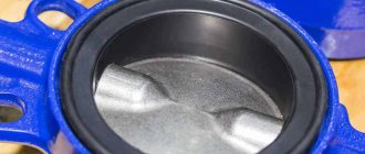
Types of return devices
The following types of check valves are used in room ventilation systems:
- air dampers - gravity and spring;
- petal (membrane);
- double-leaf butterfly type.
The elements are made of plastic, aluminum alloy, galvanized or stainless steel. Some have combined models - a metal body, a plastic sash.
Galvanized dampers are used primarily in industrial ventilation systems. They are used to cut off the reverse flow or regulate the amount of air - manually or using an electric drive, shown in the photo. Plastic ventilation fittings are used indoors, stainless steel – outdoors.
Addition. Check valves also include ventilation grilles with horizontal rotating louvres. The principle of operation is similar - under the influence of gravity, the rectangular doors close, preventing outside air from entering the channel.
Let's give a short commentary on the video. Not all the master’s words correspond to reality, but he does one thing right: he installs an external grille with gravity doors.
Adjusting the compressor pressure
As mentioned above, after creating a certain level of air compression in the receiver, the pressure switch turns off the unit’s engine. Conversely, when the pressure drops to the switching limit, the relay starts the engine again.
But often situations that arise force you to change the factory settings of the pressure switch and adjust the pressure in the compressor at your discretion. You can only change the lower switching threshold, since after changing the upper switching threshold upward, the air will be released by the safety valve.
Pressure adjustment in the compressor is carried out as follows.
- Turn on the unit and record the pressure gauge readings at which the engine turns on and off.
- Be sure to disconnect the device from the power supply and remove the cover from the pressure switch.
- After removing the cover, you will see 2 bolts with springs. The large bolt is often designated by the letter “P” with the signs “-” and “+” and is responsible for the upper pressure, upon reaching which the device will be turned off. To increase the level of air compression, turn the regulator towards the “+” sign, and to decrease it, turn towards the “-” sign. First, it is recommended to make half a turn with the screw in the desired direction, then turn on the compressor and check the degree of pressure increase or decrease using a pressure gauge. Record at what indicators of the device the engine will turn off.
- Using a small screw you can adjust the difference between the on and off thresholds. As mentioned above, it is not recommended that this interval exceed 2 bars. The longer the interval, the less often the device’s engine will start. In addition, the pressure drop in the system will be significant. Setting the on-off threshold difference is done in the same way as setting the upper on-off threshold.
In addition, you need to configure the gearbox if it is installed in the system. It is necessary to set the compression level on the gearbox to a level that corresponds to the operating pressure of the pneumatic tool or equipment connected to the system.
Source
Popular compressors according to customers
Compressor PATRIOT Euro 24-240 on Yandex Market
Compressor Denzel PC 50-260 on Yandex Market
Compressor Metabo Basic 250-24 W on Yandex Market
Compressor Quattro Elementi KM 24-260 on Yandex Market
Compressor Quattro Elementi KM 50-380 on Yandex Market
The intake (unload) valve controls your rotary screw compressor's capacity (the amount of air your air compressor sucks in). By opening and closing the air inlet, the performance of the screw compressor is regulated. When the desired pressure is reached, the compressor goes into unload mode: the unload valve closes the air intake almost completely. This way, no more air can be sucked in and compressed, so the compressor screws just spin without doing anything. At the same time, the pressure that is still present inside the screw block is released through a small hole (you will hear a hissing sound).
Design and principle of operation of the pressure regulator
A gas pressure regulator or pressure reducing valve is designed to reduce the pressure in the line diverted from the main line and maintain this pressure at a constant level.
Pressure regulators are used to maintain the pressure required for the operation of pneumatic, gas or other equipment.
For example, pressure reducing valves are installed on gas cylinders and allow you to adjust the required pressure in the line discharged to the consumer. Reducing valves installed on cylinders are often called pressure reducers, since they reduce or reduce the pressure in the outlet line (reduction - reduction, reduction, reduction).
Controls and technical characteristics
The most widely used emergency valves installed on domestic heating and water supply systems have mechanical autonomous control. They operate independently when the maximum pressure is reached and are adjusted manually. Complex production plants and piping systems use safety valves that can be remotely controlled and adjusted. As a rule, when communication with the control center is lost, such a valve turns into a regular mechanical one.
Excess pressure relief valves, based on their purpose, design, and material of manufacture, have different sets of characteristics.
The main ones are:
- Trigger pressure.
- Reset pressure.
- Performance of the working environment reset channel.
- Response speed.
- Time to return to its original state (if the valve does this automatically).
A specific emergency overpressure relief valve is also characterized by the type of design, weight and size parameters, connection dimensions
How to choose and where to install an air relief valve
Air always travels through pipelines and water heating devices in different quantities. It remains in the lines when the system is filled, penetrates the walls of the polymer pipes and is released from the coolant (water contains oxygen in dissolved form). Removing the resulting bubbles is a task that is solved by an important element of the circuit - the air vent. Next, we will look at the types of air relief valves and explain where they need to be installed.
Main varieties
Check valve systems, depending on their design, can be:
- straight type;
- corner;
- spring;
- ball;
- installed using flanges;
- casement;
- mounted by soldering;
- manufactured for disassembly.
Direct type check valve for high pressure stations
The material of manufacture may also vary, depending on what environments such a device will come into contact with during operation. In particular, it can be either metal alloys of various types or plastic.
Depending on the type of shut-off element used, check valves can be:
- with a shut-off element made in the form of a flat valve;
- ball;
- membrane;
- petal;
- with gravity grid.
The last three types of devices are used for installation in ventilation systems. Among check valves and safety valves installed on compressors, ball-type devices are the most popular, since they are less critical to contaminants present in the working environment.
Check valves with cone (a), flat (b) and spherical (c) shut-off elements
Among the most modern valve systems, it is worth noting electromagnetic type devices, in which the movement of the valve is controlled not by a spring, but by an electromagnet. Meanwhile, due to the rather high cost and not too much reliability, such devices are not very popular, inferior to cheaper and time-tested spring analogues.
Where are the air release valves located?
In any water heating system there are places where the installation of air vents is mandatory. If we talk about Mayevsky’s taps, then they need to be installed on all batteries in order to bleed off the collected air. The exact location is in the plug of the upper corner, distant from the point of connection of the supply line to the device. An air bubble forms there.
If the boiler is equipped with a built-in air vent, then there is no need to install it on the supply
The automatic air valve must be installed strictly vertically at the following points in the heating network:
on both underfloor heating collectors;
In addition to the indicated points, air vents are installed in problem areas of the heating network, where, due to difficult installation conditions, pipes form U-shaped loops turned upward. For example, a highway goes around a doorway or flight of stairs at the top, and then goes down again. In such compensators, air pockets form with a 100% probability, so an air vent is needed, preferably an automatic one.
When the highest point of the network is a pipe or compensator, a valve is mounted on it
Advice. Never cut the Mayevsky valve directly into the pipeline, since the bubbles will pass by it along with the coolant flow and the valve will be useless. For proper operation, a manual “bleeder” needs a chamber to collect air (the “automatic” has its own). Make a vertical pipe into the main line, which will serve as an air collector, and install a faucet on top.
If, when filling the heating network with water, you do not want to run between the radiators with a screwdriver, install automatic corner air vents instead of Mayevsky valves. This option is also suitable for residents of centrally heated apartments: air pockets often occur in cast iron radiators, and there is no way to remove them from there.
Another tip. To prevent the corner air vent flask from sticking out in plain sight and clinging to the curtains, take a mini-model of the valve built into the radiator cap.
Connection
Based on the type of connection, the following types of devices are distinguished:
- Threaded. Used for small diameter pipelines and low pressures typical for domestic systems. Most convenient for installation and dismantling for possible repairs and maintenance.
- Flanged. It is used in medium and large diameter pipelines and can withstand high pressure. More difficult to install/dismantle.
- Welded. The most durable and airtight connection. It is used on main pipelines and especially critical high-pressure systems. The most difficult to install and dismantle.
Flanged and welded connections are rarely used in domestic systems.