Screw mechanism
TO
category:
Mechanical Engineering
Screw mechanism
Next: Crank mechanism
A screw mechanism usually has three links: a stationary post, a screw and a nut. Depending on how these links are connected to each other, various kinematic pairs are formed:
1. The driving link is a screw with a smooth neck that rotates in a strut bearing. In this case, the screw does not have the ability to move translationally, i.e., it forms a rotational pair with the stand.
The nut forms a screw pair with the screw and can move translationally along the stand, but does not rotate, i.e., it forms a translational pair with the stand.
In this type of mechanism, the rotational movement of the screw is converted into the translational movement of a slider attached to a nut. With one revolution of the screw, the slider moves forward by the pitch of the helix. The mechanisms of the transverse and upper slides of the lathe support have such a device.
2. The driving link is a screw, forming a screw pair with a stand to which a fixed nut is fastened.
The screw, through a smooth neck at the end, is connected to the slider bearing and forms a rotational pair with it. The slider moves translationally along the guides of the rack (translationally
3. The driving link is the nut, and the screw is the driven link. If you impart a rotational movement to the nut so that it cannot move longitudinally, then the nut forms a rotational pair with the stand. In this case, the screw will move progressively provided that it is not able to rotate.
In this type of mechanism, the rotational-translational movement of the screw is converted into the translational movement of the slide. This mechanism is used in screw presses and parallel bench vices.
Rice. 1. Screw mechanisms, where the leading links are: a - a non-moving screw; b - moving screw.
Rice. 2. Screw mechanisms, where the leading links are: a - a moving screw of a bench vice; b - nut.
Thus, the rotational movement of the nut is converted into the translational movement of the screw.
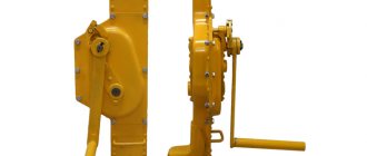
A mechanism of this type is used in screw jacks, in some parallel bench vices, in which the screw is rigidly fastened to a movable rear jaw (slider), and the nut rotates in the strut bearing by means of a handle.
Rice. 3. Compass meter.
Screw mechanisms are used in a wide variety of devices. By connecting screws with right-hand and left-hand threads, it is possible to obtain tensioning devices used in coupling cars, for tensioning cables and guy ropes for sports equipment, the same device is used for a drawing compass-measurement.
Screw jacks, like vices, are sometimes made with a stationary nut attached to a stand and a rotating screw. A thrust disk (cup) is made at the end of the screw, which forms a rotational pair with the screw.
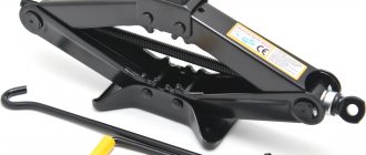
Automotive screw jacks often have two screws, with right-hand and left-hand threads. One of these screws (larger diameter) is the main one, and the second (smaller) is screwed into it. With each revolution of the large screw, the load rises to a height equal to the sum of the thread pitches of both screws,
Types of screws
Classification of fasteners can be carried out on various grounds. They can be divided into several large groups according to the operating principle, head and slot shape. In addition, there are specific parts for certain types of operations. For example, for fine control (tension, distance, etc.) an adjusting screw is used. It is used in various devices from embroidery hoops to complex mechanisms.
By purpose
For rigid fixation, a set (or locking) screw is used, for a detachable connection, a fastening screw is used. The latter has a head, which, on the one hand, presses the parts to be fastened, and on the other, facilitates installation and dismantling.
Some of them have a secret part designed to prevent third parties from removing the fasteners. Special screws are available for fixing car wheels, requiring a unique wrench to work with them. Different types of materials require certain preparatory manipulations to obtain reliable connections. If both products have a non-flat surface , at the points where the screws will be located, it is processed so as to obtain flat areas for the nut and head. Otherwise, the fastener may become distorted, which will create unnecessary stress in the configuration and may lead to bolt breakage. For thin products, local thickenings should be provided for threading. If the structures being fastened are soft , it is recommended to make dense bushings for the screws. The same devices made from insulating materials are well suited for connecting products that have a potential difference. Another solution to this problem is to use non-metal screws.
Installation products are used to fix the relative position of structures relative to each other. They have bulges or grooves at the ends to provide better retention in a given position. Special holes can be created for these configurations. The ends of the fasteners can have the shape of a cylinder, cone, drill, and sometimes a more complex design (for example, stepped).
Fastening
Installation
According to the shape of the head
The head shape of fasteners can be semicircular (slightly convex) or flat. Sometimes there are also round heads: this design has no functional purpose and is intended to create externally attractive fittings. There are structures in the shape of a mushroom - low and having the appearance of a sphere on top.
You can also find a screw with countersunk head. A similar configuration is also used in screws. It has a cone shape and a flattened outer surface. The products are designed for installation so that the tops are recessed into the material. There is also a semi-secret version, characterized by a rounded top.
Another type is an internal hexagon screw . Its thread is incomplete, and the head is cylindrical in shape. It has a hexagonal recess designed for a special key.
By type of splines
The shape of the slot can be very different. The most common options:
- A straight standard slot that requires a screwdriver with a wedge tip to work with. If such a tool is not nearby, a chisel or knife can be used.
- Slot in the form of a cross.
- "Torx" with five or six beams. Dimensions can vary from 0.1 to 10 cm.
- A star with 12 rays, the tops of which form angles of 60 degrees.
- Robinson slot with square recesses for screwing in and out.
There are a number of other design options. One example is a vandal-proof slot , which provides only a twisting option. Because of this feature, it was called One Way. It will not be possible to dismantle it by unscrewing it: to do this you will need to cut or drill out a screw. Another type of spline is the Bristol spline , used in soft metal products. It is characterized by 2 or 3 pairs of radial rays.
Criterias of choice
The diameter by a number of parameters: features of the materials, configuration of the parts to be connected, the magnitude of the acting loads. If you use a screw that is too thick, the product may be damaged.
It is important to choose the right length : if it is insufficient, the connection will be fragile. It is good if design documentation with a list of fasteners has already been developed for the work. It provides information on which screws are needed for the connections.
Demanding components require fasteners made of high-strength metals. If work is carried out outdoors , it is important that the screws are resistant to oxidation. Suitable materials in this case are silicon bronze and steel alloys with chromium and nickel.
Simple mechanisms.
Screw mechanisms.
They are used in devices with manual fastening of workpieces, in mechanized devices, as well as in automatic devices.
They are simple, compact and reliable in operation. Screw terminals are the most commonly used. Their features include: large clamping forces with small initial ones; versatility - for securing a wide variety of parts; self-braking - the initial force acts only at the moment of fastening. Disadvantages include low productivity and wear. They are mainly used in single and small-scale production.
An example of fastening with a screw clamp is shown:
The nominal diameter of the screw in mm is determined from the ratio:
where C = 1.4 coefficient for metric threads;
Q – workpiece fixing force, N;
s - permissible tensile (compressive) stress (for screws made of steel 45 - s = 80 - 100 MPa).
How to prevent a screw from self-unscrewing
Spontaneous unscrewing often occurs due to shaking and similar dynamic loads . There are different methods to prevent it. One example is washers made of elastic materials , mounted under the head or in a nut, as well as paired parts of the “NordLock” type . On sale you can find screws equipped with such devices. Another option is wire locks that connect adjacent fasteners and prevent self-unscrewing. Sometimes spring washers . For better adhesion of the fastener to the part, you can apply a little paint or varnish near the head.
Wire clamp
Polyamide washer
NordLock
Grover spring washer
Ball screw history
A similar structure is installed over a long period. It is generally accepted that the first ball screw was created from an ordinary screw on which several nuts were fixed. Further improvement of the design was carried out as follows:
- Nut redistribution.
- Changing the direction of tension.
- Reduced pitch error.
In the production of basic elements, materials can be used that are highly resistant to mechanical and other impacts. That is why the mechanism began to be installed more often than before.
Ball screw application
Only with proper operation of the device can its long service be ensured. An example is the cleanliness of the work surface, protecting the work space from environmental influences. It is recommended to exclude the possibility of abrasive elements and chips, as well as dust, getting on the surface.
Most problems can be solved by installing corrugated protection, which is made of rubber, polymer or leather. Their installation eliminates the possibility of contaminants entering the contact zone.
Another method is to install a compressor unit. It supplies filtered air under pressure, which cleans the surface of contaminants. Other features include the following:
- The ball screw has a certain preload, which eliminates the possibility of backlash.
- The absence of backlash largely determines the possibility of installing the device in CNC machines and other equipment that must operate with high precision.
When choosing the most suitable drive, operating conditions are taken into account. The ball screw lasts much longer with generous addition of lubricant, since friction occurs during operation. Too much friction causes increased wear and thermal expansion of the metal.
Disadvantages of Ball Screws
The type of drive in question also has several significant disadvantages that must be taken into account. A pair of ball screw gears is characterized by the following disadvantages:
- Depending on the installation angle of the main element, there is a possibility of reverse motion of the ball screw.
- The low friction of the nut does not block it during reverse movement. In other words, it can move freely along the screw, so a locking element is provided.
The device in question is not recommended for installation in case of manual feed. In addition, do not forget about the high cost of the product. That is why in the mechanical engineering and other industries they often use low-cost options that are easier to manufacture and can last for a long period.
Characteristics of ball screws for CNC equipment
As previously noted, quite often the drive in question is used to ensure reliable operation of a CNC machine. The main characteristics are the following:
- Length of the running rod. As practice shows, in most cases a rod about 2 meters long is sufficient. It is extremely undesirable to install a version with a long length, since the applied load can cause deformation and a decrease in basic performance characteristics.
- Linear high-speed movement. When manufacturing CNC machines, attention is paid to ensuring that the main elements move at high speed. Due to this, the efficiency and processing speed are significantly increased, and the scope of application of the device is expanded.
- The most important parameters are the diameter and pitch of the screw. It is these characteristics that determine what load can be placed on the device.
- During production, quite a lot of attention is paid to precision. This indicator can vary from C1 to C10.
The engine can transmit rotation directly or through safety elements, for example, special couplings. They can significantly reduce the likelihood of defects.
Advantages of Ball Screws
There are quite a large number of advantages that can characterize the drive in question. The most significant are the following:
- The low coefficient of friction can be called the main advantage of the ball screw. This indicator is achieved through the use of a special material, as well as the addition of a lubricant to the contact area.
- High efficiency is also the most important advantage that makes the ball screw superior to many other designs. An example is that in most cases the figure is 90%, for metric lead screws it is only 50%.
- The absence of slipping significantly increases the service life of the ball screw device. This phenomenon causes strong friction, which increases wear and increases the temperature of the structure.
- You can carry out repairs and maintenance yourself; this does not require special equipment. This reduces equipment downtime during repairs, as well as periodic lubrication.
- The higher speed of the lead screw significantly expands the scope of application of the design.
- Lower power requirements for the electric propeller drive.
All of the above advantages determine that many do not pay attention to the cost and install the structure. When choosing, attention is paid to the type of material used in manufacturing, accuracy and many other points.
Ball recycling systems
An important design element is the ball recirculation system. It is characterized by the following features:
- The balls change their position in the thread channels of the nut and special raceways of the screw. Moreover, they are characterized by precise dimensions. In the manufacture of balls, steel with a high level of wear resistance is used. Otherwise, play may occur, which will negatively affect the performance of the ball screw.
- If you didn’t use a special system, then at the end of the stroke the balls would simply run out of the structure. This is why return systems are often used when creating structures.
- The external system is represented by a metal tube that connects the inlet and outlet. The internal system is represented by channels cut near the screw.
Recently, a design option in which the movement of the balls is looped has become widespread. This ensures the most favorable operating conditions for the device.
Ball screw accuracy
In most cases, a ball screw is installed due to the high positioning accuracy of both elements. The operating principle is characterized by the following features:
- In most cases, the error is 1-3 microns per 300 mm of travel. In addition, you can find ball screw devices with higher positioning accuracy of individual elements.
- The blank for the screw is obtained using machining technology. An example is the use of a CNC lathe, as it allows you to obtain dimensions with high accuracy.
- After obtaining the required shape, the surface is hardened and polished. The first technological process allows to significantly increase the surface hardness, the second to achieve high dimensional accuracy.
An important point is that temperature treatment causes a significant change in the basic qualities of the material. That is why finishing in most cases is represented by grinding.
Hard-whirling technology has become quite widespread today. This metalworking technology provides for minimal heating of the workpiece, which significantly increases the accuracy of processing. In most cases, the machining accuracy is 250 Nm per centimeter.
Milling and grinding technology can also be used on ultra-precise equipment. Similar equipment is used to produce mirrors and lenses. In most cases, the workpiece is represented by Invar alloys, due to which the error in production is significantly reduced.
