Safety check valve for a compressor: types, design, DIY production
In order to ensure the correct operation of compressor units used almost everywhere today, a number of additional technical devices are used, one of which is a check valve for the compressor. Such a valve, which is equipped with the vast majority of compressor units today, also protects them from premature failure and ensures smooth starting.
Check valve on compressor
Purpose, design features and scope of application
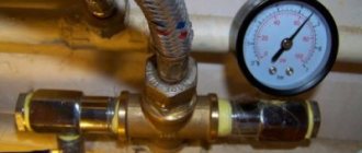
A check valve installed at the outlet of the compressor head allows compressed air to pass in only one direction - to the receiver or any other reservoir. Thus, this valve prevents the return of compressed air located in the receiver or other elements of the pneumatic system back to the compressor. The greatest risk of compressed air returning from the pneumatic system to the inside of the compressor is during breaks in the operation of the device (if the compressor discharge valves do not fit tightly to the seats), as well as at the time of its startup.
The design of a typical compressor valve consists of the following elements:
- metal case;
- the inlet hole, which is closed by a valve (to prevent the latter from skewing during its operation, guide ribs are specially made on it);
- rubber ring;
- a spring that fits onto the valve guides;
- cork;
- sealing gaskets.
Compressor check valve device
In the check valve body, in addition to the hole through which it is connected to the compressor using a fitting, there is one more hole: the compressor unloading valve is connected to it. The purpose of such a safety valve on the compressor is to prevent the permissible pressure in the working chamber from exceeding.
The operating principle of compressor check valves is as follows.
- The compressed air generated by the compressor enters the valve inlet.
- Under the influence of compressed air pressure, the spring is compressed, opening the valve and allowing air into the pneumatic system.
- After the compressor is turned off and the air pressure in the working chamber drops, the spring expands and blocks the air line.
Working principle of the air check valve
If the air pressure in the working chamber at the moment when the compressor is turned off exceeds the permissible value, the safety valve, also installed at the outlet of the device, is activated. The design of the compressor unloading or safety valve uses a ball-type locking element, pressed against the edges of the inlet opening by a special spring. If the force created on such a ball by compressed air exceeds that to which the spring is adjusted, the valve opens, due to which the pressure is normalized.
Safety valves in pneumatic systems can also be installed on tanks, in particular on receivers. In this case, the purpose of such valves is to prevent a decrease in the pressure of the compressed air pumped into the tank.
Brass check valves for compressor installations
Devices operating on the principle of a check valve, that is, cutting off the flow of the working medium when it moves in the wrong direction, are used in various fields. In particular, they are used for installation in:
- systems designed for suction of liquid media;
- pipelines through which hot gases are transported;
- piping systems used in refrigeration units;
- air conditioning and ventilation systems;
- sewer systems.
Check valves used in systems for transporting liquid media are designed to prevent these media from entering the compressor, which may become unusable as a result. When transporting hot gases, these devices are also used to prevent gases from reaching other elements of the system.
Non-return valve (siphon) for air conditioner. Designed to connect the drainage pipeline to the central sewerage system
Safety valve for compressed air receivers
Group: Forum participants Messages: 3753 Registration: 10.1.2011 From: Saransk User No.: 88830
Approved by order of the Federal Service for Environmental, Technological and Nuclear Supervision dated December 15, 2020 N 536 FEDERAL STANDARDS AND RULES IN THE FIELD OF INDUSTRIAL SAFETY “INDUSTRIAL SAFETY RULES” WHEN USING EQUIPMENT OPERATING UNDER EXCESSIVE PRESSURE"
350. The throughput capacity of safety valves is determined in accordance with the ND, taking into account the flow coefficient for each valve (for compressible and incompressible media) and the cross-sectional area of the valve to which it is assigned, specified in the safety valve passport. When the safety valves are operating, the pressure in the vessel is not allowed to exceed the permitted pressure: a) by more than 0.05 MPa - for vessels with a pressure of less than 0.3 MPa; b) more than 15% - for vessels with pressure from 0.3 to 6 MPa inclusive; c) more than 10% - for vessels with pressure more than 6 MPa. When the valves are operating, it is allowed to exceed the pressure in the vessel by no more than 25% of the permitted pressure, provided that this excess is provided for in the operating manual (instructions) for the vessel. If during operation the operating pressure of the vessel is reduced, then it is necessary to calculate the capacity of the safety valves for the new operating conditions.
354. The environment leaving safety devices must be diverted to a safe place. Discharged toxic, explosive and fire-hazardous process media must be sent to closed systems for further disposal or to organized combustion systems. In cases justified by design documentation, the discharge of non-toxic explosive and fire hazardous media into the atmosphere through discharge pipelines is allowed, provided that their design and placement ensure explosion- and fire-safe dispersion of the discharged environment.
358. The procedure and timing for checking the serviceability of operation, repairing and checking the response settings at the stand of safety devices, depending on the conditions of the technological process, must be specified in the production instructions for the operation of safety devices, approved by the management of the operating organization. In the manner established by production instructions: the results of checking the settings of safety devices are documented in acts and reflected in the appropriate journal; the results of checking the serviceability of safety devices and information about their settings are recorded in a shift (operational) journal or other operational documents, the forms and procedure for maintaining which are established by administrative documents in the operating organization.
Group: Forum Members Messages: 53 Registration: 10/17/2019 User No.: 367231
Hello, are you from Ukraine? When communicating, I will rely on the regulatory documentation of the Russian Federation. Perhaps yours is a little different.
Who is checking you? It is important. 1) Rostechnadzor? Because according to FNiP “Industrial Safety Rules for the Use of Equipment Operating under Excessive Pressure” (hereinafter referred to as FNiP) 223. The following pressure equipment is not subject to registration with Rostechnadzor and other federal executive authorities authorized in the field of industrial safety: a) . as well as vessels working with the environment of the 2nd group (according to TR CU 032/2013) at the above temperature, in which the product of the operating pressure (MPa) and capacity (m3) does not exceed 1.0.
Your vessel is not registered with the Rostechnadzar authorities (hereinafter referred to as RTN) and, accordingly, they are not obliged to check it. Unless it is indicated as a technical device of some hazardous production facility (HPF), and then the question arises of how RTN included it in the HPF.
Main varieties
Check valve systems, depending on their design, can be:
- straight type;
- corner;
- spring;
- ball;
- installed using flanges;
- casement;
- mounted by soldering;
- manufactured for disassembly.
Direct type check valve for high pressure stations
The material of manufacture may also vary, depending on what environments such a device will come into contact with during operation. In particular, it can be either metal alloys of various types or plastic.
Depending on the type of shut-off element used, check valves can be:
- with a shut-off element made in the form of a flat valve;
- ball;
- membrane;
- petal;
- with gravity grid.
The last three types of devices are used for installation in ventilation systems. Among check valves and safety valves installed on compressors, ball-type devices are the most popular, since they are less critical to contaminants present in the working environment.
Check valves with cone (a), flat (b) and spherical (c) shut-off elements
Among the most modern valve systems, it is worth noting electromagnetic type devices, in which the movement of the valve is controlled not by a spring, but by an electromagnet. Meanwhile, due to the rather high cost and not too much reliability, such devices are not very popular, inferior to cheaper and time-tested spring analogues.
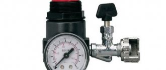
Safety valves for compressors
Safety valves are widely used in compressor installations, and compressor equipment in general. We will not dwell in detail on what a safety valve is and what it is intended for, because... We are sure that visitors to our site know this well themselves. Let’s just briefly say that: a safety valve is used to discharge (usually into the atmosphere) compressed air if its pressure exceeds a certain maximum permissible value - which usually happens if the control automation fails for any reason. Sometimes, however, the safety valve operates due to incorrect settings of the equipment operating parameters.
We supply high quality German made safety valves for air compressors. Of course, the valves we offer can also be used on air receivers, as well as other compressor equipment.
| One of the safety valves we supply: Honeywell Braukmann 1144.02, operating 15 bar(g) |
Technical data: Series 229, “heavy-duty”, full opening
For all models of the 229 series: - intended for compressed air and non-toxic, non-flammable gases - cannot be used for liquids and steam! — cannot be reconfigured, must be ordered with a fixed working pressure! — operating temperature -10…+200 °C — body construction material copper, springs carbon steel, FPM seals (fluoroplastic) — range of possible operating pressures for valves with a certain DN: G½: 0.5…25 bar G¾: 0.5… 22 bar G1: 0.5…20 bar G1¼: 0.5…22 bar G1½: 0.5…16 bar G2: 0.5…12 bar
| Type | Attach. G, inches | Possible exhaust pressure, bar | Height, mm | Flow section, mm | Valve 229.01 | |
| Without thread | Threaded part | |||||
| 229.01 | ½ | 0,5…25 | 95 | 14 | 12 | |
| 229.02 | ¾ | 0,5…22 | 110 | 16 | 15 | |
| 229.03 | 1 | 0,5…20 | 135 | 18 | 20 | |
| 229.04 | 1¼ | 0,5…22 | 155 | 20 | 25 | |
| 229.05 | 1½ | 0,5…16 | 180 | 22 | 32 | |
| 229.06 | 2 | 0,5…12 | 205 | 25 | 40 | |
Series 229 valve capacity in m³/h @ 0°C and 1013.25 mbar(a)
| Joining → | G½ | G¾ | G1 | G1¼ | G1½ | G2 |
| Response pressure ↓ | ||||||
| 0.2 bar | 62 | 92 | 158 | 239 | 385 | 594 |
| 0.5 bar | 84 | 135 | 214 | 314 | 497 | 722 |
| 1.0 bar | 124 | 196 | 307 | 459 | 741 | 1058 |
| 1.5 bar | 153 | 239 | 402 | 637 | 1029 | 1653 |
| 2.0 bar | 200 | 317 | 495 | 752 | 1205 | 1746 |
| 2.5 bar | 223 | 349 | 590 | 921 | 1469 | 2002 |
| 3.0 bar | 276 | 431 | 674 | 1024 | 1630 | 2436 |
| 4.0 bar | 346 | 541 | 846 | 1285 | 2046 | 3057 |
| 5.0 bar | 416 | 650 | 1017 | 1546 | 2461 | 3678 |
| 6.0 bar | 487 | 760 | 1189 | 1807 | 2877 | 4300 |
| 7.0 bar | 557 | 870 | 1361 | 2068 | 3293 | 4921 |
| 8.0 bar | 627 | 980 | 1533 | 2329 | 3709 | 5542 |
| 9.0 bar | 698 | 1090 | 1705 | 2590 | 4124 | 6164 |
| 10.0 bar | 768 | 1200 | 1876 | 2851 | 4540 | 6785 |
| 12.0 bar | 909 | 1420 | 2220 | 3374 | 5372 | 8027 |
| 14.0 bar | 1049 | 1639 | 2564 | 3896 | 6203 | — |
| 16.0 bar | 1190 | 1859 | 2907 | 4418 | 7034 | — |
| 18.0 bar | 1331 | 2079 | 3251 | 4940 | — | — |
| 20.0 bar | 1471 | 2298 | 3595 | 5462 | — | — |
| 22.0 bar | 1612 | 2518 | — | 5984 | — | — |
| 25.0 bar | 1823 | — | — | — | — | — |
Technical data: Series 1144/1145, “extra-heavy-duty”, proportional opening
For all models of the 1144/1145 series: - designed for compressed air and non-toxic, non-flammable gases - increased resistance to vibration - cannot be used for liquids and steam! — cannot be reconfigured, must be ordered with a fixed working pressure! — operating temperature -10…+260 °C — body construction material bronze, spring casing copper (up to G1) or bronze (starting from G1¼) — range of possible operating pressures for all valves of the 1144/1145 series: 0.5…20 bar — on request, working pressure up to 30 bar
| Type | Attach. G, inches | Possible exhaust pressure, bar | Height, mm | Flow section, mm | Valve 1144.03 | |
| Without thread | Threaded part | |||||
| 1144.01 | ½ | 0,5…20 | 138 | 12 | 10 | |
| 1144.02 | ¾ | 0,5…20 | 153 | 15 | 15 | |
| 1144.03 | 1 | 0,5…20 | 185 | 16 | 20 | |
| 1145.01 | 1¼ | 0,5…20 | 231 | 18 | 25 | |
| 1145.02 | 1½ | 0,5…20 | 293 | 20 | 32 | |
| 1145.03 | 2 | 0,5…20 | 367 | 22 | 40 | |
Series 1144/1145 valve capacity in m³/h @ 0°C and 1013.25 mbar(a)
| Joining → | G½ | G¾ | G1 | G1¼ | G1½ | G2 |
| Response pressure ↓ | ||||||
| 0.5 bar | 61 | 138 | 245 | 382 | 626 | 978 |
| 1.0 bar | 83 | 186 | 331 | 517 | 847 | 1323 |
| 2.0 bar | 126 | 283 | 503 | 786 | 1287 | 2011 |
| 3.0 bar | 169 | 380 | 675 | 1055 | 1728 | 2700 |
| 4.0 bar | 212 | 477 | 847 | 1324 | 2169 | 3388 |
| 5.0 bar | 255 | 573 | 1019 | 1593 | 2609 | 4077 |
| 6.0 bar | 298 | 670 | 1191 | 1862 | 3050 | 4766 |
| 7.0 bar | 341 | 767 | 1364 | 2131 | 3491 | 5454 |
| 8.0 bar | 384 | 864 | 1536 | 2400 | 3931 | 6143 |
| 9.0 bar | 427 | 961 | 1708 | 2669 | 4372 | 6831 |
| 10.0 bar | 470 | 1058 | 1880 | 2938 | 4813 | 7520 |
| 11.0 bar | 513 | 1154 | 2052 | 3206 | 5254 | 8209 |
| 12.0 bar | 556 | 1251 | 2224 | 3475 | 5694 | 8897 |
| 13.0 bar | 599 | 1348 | 2396 | 3744 | 6135 | 9586 |
| 14.0 bar | 642 | 1445 | 2569 | 4013 | 6576 | 10274 |
| 15.0 bar | 685 | 1542 | 2741 | 4282 | 7016 | 10963 |
| 16.0 bar | 728 | 1638 | 2913 | 4551 | 7457 | 11652 |
| 17.0 bar | 771 | 1735 | 3085 | 4820 | 7898 | 12340 |
| 18.0 bar | 814 | 1832 | 3257 | 5089 | 8338 | 13029 |
| 19.0 bar | 857 | 1929 | 3429 | 5358 | 8779 | 13717 |
| 20.0 bar | 900 | 2026 | 3601 | 5627 | 9220 | 14406 |
High pressure safety valves and other safety valves
We also supply safety valves for high pressure compressors, with a possible response pressure of up to 50 bar, belonging to the 226 and 227 series. We also supply valves for pressures up to 60 bar (series 218) and stainless steel safety valves (series 218- ES).
We also supply safety valves with G1/8″, G¼” and G3/8″ connections.
Please contact our staff for information on these types of valves.
Recommendations for selection
When choosing a check valve, you should consider a number of parameters. These include, in particular:
- the intensity of the air flow that will be transported through the system;
- the performance of the air exchange device on which the check valve will be installed;
- the power of the air pumping device, which can be a compressor or fan;
- the degree of contamination of the working environment that will be transported through the elements of the system being created;
- temperature operating conditions.
In addition, it is necessary to take into account the type of medium with which the elements of the valve device will come into contact. This parameter has a direct impact on the choice of valve material, which must have the required durability.
Types of equipment
On the market you can find devices of various form factors, as well as purposes. Equipment is usually distinguished by design features, as well as by installation method. The choice of a particular device directly depends on the tasks assigned to it.
Design types of check valves:
- classic (straight);
- ball;
- corner;
- spring;
- on flanges;
- constipation;
- soldered;
- for beading.
The performance of the device is also affected by the material of manufacture. Check valves made of metal alloys are used in industrial structures where heavy loads are expected. Whereas plastic mechanisms can be seen in ordinary kitchens and bathrooms.
Regardless of the design, check valves can be:
- membrane;
- flat;
- lattice;
- ball;
- petal.
The former can often be found in ventilation equipment. Ball valves are used in compressors, and other types are used in gas and plumbing lines. There are also advanced mechanisms with electromagnetic locking.
The cost of the latter, naturally, is noticeably higher. In this case, the blocking occurs not by means of a conventional spring spring, but by means of an electromagnet. But such valves are picky about distillation products and volumes, so manufacturers of industrial equipment most often give preference to more durable and reliable spring analogues.
How to make a check valve for a compressor with your own hands
The modern market offers a wide variety of check valves for compressors of various types and capacities. Meanwhile, if you want to save money, you can make a valve for the compressor yourself. In order to make such a valve, it is not necessary to know the structure of an air compressor; it is enough to understand how such a compressor works. Moreover, you will not need expensive consumables and complex equipment, as well as special knowledge, skills and experience in performing work of this kind.
Device Features
Check valves are used in many applications. Such devices most often work in tandem with some kind of tanks or compressors. The main task of a check valve is to prevent loss of pressure built into the system and limit the access of unwanted elements into the system.
In the absence of such a mechanism, the efficiency of the equipment decreases noticeably. For example, compressors are forced to work almost non-stop, which affects not only the operational life of the equipment, but also electricity bills.
Areas of application for check valves:
- systems operating with the distillation of liquid media;
- gas lines;
- refrigeration equipment;
- ventilation;
- plumbing equipment.
In addition to maintaining system pressure, check valves prevent liquid media from entering the compressor. With large volumes of distillation, as well as a serious load on the equipment, it is very important to maintain the tightness of the equipment. This point is also critical when working with gaseous compositions, especially hot ones.
In air conditioning and similar equipment, such valves perform two important functions:
- Limit the access of reverse condensation.
- Ensure unhindered distillation of freon from the hot part of the evaporator to the cold part.
Check valves are often used in ventilation technology, both in domestic and industrial areas. Equipment of this type can be seen in apartments - kitchens and bathrooms, in offices, catering establishments, as well as on construction sites and other technical facilities.
The check valve performs the following functions:
- improves the quality of traction on complex multi-level sections;
- limits the access of cold flows from the outside;
- protects the room from the penetration of toxic environments, as well as unpleasant odors;
- In case of fires, it prevents the ingress of combustion products.
In a similar way, check valves are used in plumbing and other systems where it is necessary to shut off unwanted elements.
Purpose, design features and scope of application
There are quite a large number of protective safety devices that can significantly increase the service life of the compressor. The device in question has design features that make it possible to control the movement of the medium in only one direction. In other words, the valve prevents the reverse flow of compressed air, for example, when the device stops operating. The check valve for the compressor is represented by a combination of the following elements:
- Metal body. It is characterized by high resistance to environmental influences.
- Rubber ring.
- A spring that fits over the guide lugs.
- A plug that ensures the mechanism is closed.
- Sealing gasket. It significantly increases the degree of tightness of the check valve.
- Hole for connecting the compressor unloading valve.
A similar compressor check valve device is designed to relieve excess pressure in the system, as well as prevent return air flow. The design is also made by hand to achieve a similar goal. The operating principle is characterized by the following features:
- Air under pressure is supplied to the inlet. It can have a wide variety of diameters.
- The created pressure compresses the spring, due to which the passage hole opens. The spring is made of a special corrosion-resistant material, which ensures a long service life.
- When the compressor is turned off, the spring returns to its position and the line is closed. Due to this, the possibility of reverse flow of the medium is eliminated.
The above information indicates that the design of the mechanism is quite simple and reliable in operation. The purpose and features of the mechanism determine its very wide distribution.
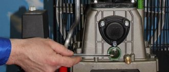
Installation Rules
The overpressure relief valve should be installed as close to the compressor as possible. On low-power mobile units, the installation location is provided by the manufacturer. When installing distributed stationary systems, the distance from the compressor outlet to the valve should not exceed 1.5 meters. It is unacceptable to install an emergency release device after the shut-off valve. If the valve is closed for any reason, the valve will not be able to fulfill its protective function, and the increased pressure can seriously damage the equipment or even cause an accident that threatens the life and health of people working nearby.
Before installing or replacing the valve, it is necessary to completely relieve the pressure in the system and turn off the power to the compressor motor. The threaded connection should be wrapped with FUM tape or plumbing thread. First, the threaded connection is tightened by hand, and only after making sure that the thread goes in smoothly can significant physical effort be applied to tighten it with a wrench.
After installing the valve, you need to test it by increasing the pressure in the system to a threshold value. It should work and reset. If this does not happen, the installation cannot be operated until the cause of the failure is identified and eliminated. If the valve is adjustable, you need to use an adjusting hex key to set its operating reset value, using the pressure gauge built into the compressor control unit.
Main varieties
The receiver valve in question can be classified according to a fairly large number of characteristics, the main one being the design features of the mechanism. The following execution options are available:
- Angular.
- Straight type.
- Ball.
- Spring.
- Attached by flange.
- Casement.
- Installed using soldering technology.
- Made for beading.
The classification is carried out according to the type of material used in manufacturing. Most often, the valve is made of metal with high corrosion resistance, but there are other options.
The locking element is also characterized by various design features. Based on this feature, the following execution options are distinguished:
Ball-type versions are quite popular. This is due to their practicality and high reliability in use.
In addition, there are versions on sale in which the locking element is controlled by an electromagnetic element rather than a spring. They are more accurate in operation, but are much more expensive.
Types of overpressure relief valves
Based on the method of pressing the locking element to the seat, the devices are divided into the following types:
- Spring. The force of elastic deformation of the spring metal keeps the shutter closed. It is selected in such a way that a pressure exceeding a given level pushes the locking element away from the seat. Spring models are available with both constant response pressure and the ability to adjust it. To do this, an adjusting screw is added to the design, which pre-compresses or weakens the spring. During operation, the spring gradually loses its elasticity, and the response value may change.
- Lever cargo. For pressing, the force of gravity is used, acting on a load suspended at the end of the lever. Such a system has wide possibilities for adjusting the response value. To increase it, the load is moved to the end of the lever, to decrease it, closer to the body. In addition to the possibilities for precise adjustment, this design has another advantage: the stability of the release pressure over long periods of time. Lever devices are characterized by large dimensions and weight. They are used as a safety valve for high-capacity compressors installed permanently.
- Electromagnetic. These advanced devices use an electromagnetic solenoid actuator to press the locking element. Such devices operate as an executive element of a centralized automated control system. The pressure sensor can be located next to the valve, or it can be located in a completely different part of the system. Most of them are equipped with an additional working spring. If there is a loss of power or communication with the control system, the relief valve turns into a regular mechanical one.
According to the method of connection, the relief valves are divided into the following types:
- Threaded. The most common type for low pressure relief devices. Easy to install and dismantle even for untrained personnel - a wrench is enough for this. Most often used as an emergency valve for a low-power mobile compressor.
- Flanged. More difficult to install and more expensive, they provide high tightness. used in medium and high pressure systems.
- Welded. Provide maximum tightness and reliability. Difficult to install/dismantle; special equipment and trained personnel are required.
Based on the material from which the device is made, there are:
- Steel. They have high strength and long service life. Withstands great pressure.
- Brass. They are characterized by high corrosion resistance and long service life.
- Plastic. Cheap, but designed for low pressure values.
Recommendations for selection
When choosing a compressor valve, you should pay attention to several main factors:
- The intensity of the air flow that is transported in the system.
- Performance indicator.
- Device power. This indicator is indicated in the operating instructions specified by the manufacturer. As power increases, valve capacity also increases.
- Degree of contamination of the working environment. Some impurities may cause the product to jam. That is why the scope of application is significantly narrowed.
- Temperature operating conditions. Too high or low temperature can cause changes in the basic properties of the material.
A mandatory selection criterion is the type of medium that will be transported in the system.
Safety valve
The relief valve (another name is safety) valve serves for emergency release of pressure and is the final device that protects the pneumatic equipment connected to the compressor from damage.
Attention! It is not recommended to operate the compressor without a safety valve.
Experts also include the following types of relief valve:
- bypass valve;
- unloading valve.
Despite minor design differences, their operating principle is identical to a safety valve.
Operating principle of the safety valve
Compressor equipment that is not intended for use in industrial environments is equipped with spring-loaded safety valves. When such a compressor operates in normal mode, it is closed (see diagram). In this case, the air pressure on its plate is balanced by a calibrated spring, which prevents the locking mechanism from opening. If the pressure suddenly increases above the set value, the pressing force of the plate against the nozzle decreases and the valve begins to open. This releases excess air, after which the locking mechanism can return to its place.
Important! If the relief valve does not return to its place for a long time, then the compressor must be turned off and the cause that caused the unauthorized increase in pressure must be eliminated
Bypass valve
The bypass (or overflow) valve maintains the pressure of the working medium at a given level. To do this, through the existing branch there is a constant, and not one-time or periodic, as in a safety valve, removal of an excess amount of the working medium (compressed air, gas, liquid), which ensures pressure stability in the system. Such valves are used, for example, in turbochargers installed on automobile internal combustion engines.
How to make a check valve for a compressor with your own hands
If you wish, you can make a check valve for the compressor yourself. Due to this, it is possible to reduce your own costs. For self-production you will need:
- Connector for connecting equipment.
- Return fitting.
- A bolt with a diameter of 3 mm and a length of 40-50 mm.
- Two nuts of appropriate sizes.
- Small pieces of rubber.
- Spring of the appropriate diameter.
- Set of tools for installation.
The manufacturing process can be divided into several main stages:
- The required limiter is created from a metal plate.
- The end surface of the fitting is sawed off to create a seat.
- A valve of the required diameter can be cut from a car inner tube.
- A plate is attached to the previously selected bolt, acting as a retainer. After this, the spring is fixed.
The assembled safety element is inserted into the fitting and then secured with two nuts on both sides. The response speed is controlled by the spring stiffness. The device in question is characterized by a simple design, but it is suitable for installation as a safety element in various systems.
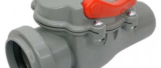
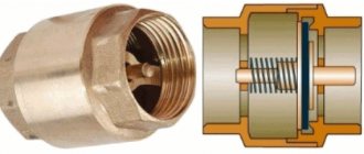
Check valve
A check valve (return valve) is a device that allows compressed air to flow in only one direction . Structurally, it is assembled (see figure) in a metal case (item 3), inside of which the following are located:
- internal shutter (item 6), blocking the inlet;
- a spring (pos. 4) pressing the rubber ring (pos. 5) to the bolt seat;
- inlet fitting (pos. 7);
- plug (item 1) with a sealing gasket made of cardboard (item 2) (the plug makes it possible to disassemble the return for repair or maintenance).
On a note! The check valve has a branch for connecting it to the receiver and a small branch for connecting a pressure switch.
Operating principle
The reverse action valve works as follows. Passing through the outlet valve of the piston cylinder, the compressed air enters the return pipe through the inlet fitting (pos. 7). Having reached a certain pressure, the air lifts the internal shutter (pos. 6) and passes through the cavity in the housing (pos. 3) into the storage tank of the receiver. When the compressor is turned off, the spring (item 4) returns the internal shutter to its place, blocking the path of air from the receiver back into the piston cylinder.