To stabilize increased traction currents and increased asymmetry currents, choke transformers are used. A choke is an inductor that can remove interference, smooth out current ripple, decouple parts of a circuit from each other at high frequencies, and also accumulate energy in a magnetic field. The device is called a “reactor” (the latter does not require the use of a drive or other driving forces, but operates on the principle of dynamics).
Thus, the main purpose of the inductor is to delay current in a certain frequency range or accumulate energy over a certain period of time in a magnetic field. The accumulated energy is used in various fields of industry and in everyday life. Let's find out more about this.
Principle of operation
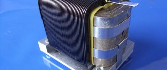
The principle of operation is based on the principle of self-induction of the coil. The design of the device contains only one winding, but due to the principle of operation and scope of application, the device is often called a choke transformer.
The coil of the device consists of plates insulated between each other (most often steel or ferromagnetic). Isolation is carried out to avoid the formation of Foucault currents, which create interference. The core has a high inductance, but at the same time it is a powerful restraining barrier (for example, during a strong increase or decrease in voltage in the network).
The device is able to withstand various vibration ranges:
- low (from 20 Hz to 20 kHz);
- medium (or ultrasonic, from 20 to 100 kHz);
- high (over 100 kHz).
High-frequency chokes differ in design from low- and mid-frequency ones.
Manufacturers
Several manufacturers are engaged in the manufacture of TD-500. Among them, the largest supply volumes are offered by:
- ETA-group, St. Petersburg, Russian Federation;
- Vintor LLC, Vinnytsia region, Ukraine;
- electrical machine-building enterprise "SELMA", Simferopol, Crimea.
Ivan Petrovich Alekseenko, welder, 35 years of work experience: “Despite the apparent bulkiness and not modern appearance, transformers for alternating current welding TD-500 are still in demand in various industries. The devices have a “Soviet” service life and will last for many years.”
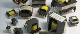
Varieties
Devices are divided into:
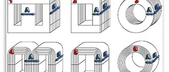
- The low-frequency choke-transformer looks similar to a primitive iron transformer. The difference is the single winding layout. The coil provides significant resistance to changes in current in the circuit - when it decreases, the device is able to maintain the required level, and when it increases, it is able to reduce it.
- High frequency circuits are more common. The coils of such devices are wound onto cores (ferrite, steel) or onto a plastic frame. When working with medium or long range waves, sectional winding is often used.
A choke with a core has smaller dimensions than one without it.
The main parameters of the device are inductance (unit of measurement - H) and resistance (Ohm). Important characteristics are voltage, rated current and quality factor.
Scheme
The welding machine TD 500 is distinguished by its simple design . The reduction characteristic is formed by high inductive leakage generated by installing the primary and secondary windings (OP and OB, respectively) along the axis of the core.
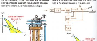
Smooth adjustment of the supplied current is made by approaching or moving the OF away from the OP. In addition, it is possible to control the current by flipping the coil, which creates two adjustment intervals:
- When setting the I interval (low currents), the coils are connected in series. A certain group of OP turns is disconnected, which leads to an increase in the open-circuit voltage at the OB contacts to 76 V. In this way, arc stability is achieved at low currents.
- In interval II (high currents), a parallel connection of coils is implemented. At the idle contacts, the OF voltage decreases to 60 V.
The intervals are changed using a drum switch with a handle located on the housing cover . The sector current-indicating mechanism is fixed on the core under the cover and connected by means of a lever to a movable coil.
The current is determined using a special scale through the sight glass of the casing. The scale gradation is made for both ranges of welding current at the rated mains voltage and at a voltage at the output contacts of the secondary circuit during welding equal to 30 V.
The equipment filter capacitance is formed from capacitors C, which reduce radio interference generated during work. Also the function of filters is to increase power .
Scope and purpose of DC chokes
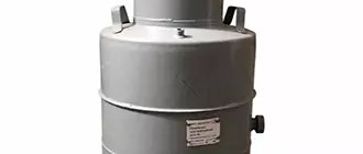
Devices, for example, the choke-transformer DT-0.6-1000, are intended for installation on railway tracks that are equipped with automatic AC blocking and DC electric traction. Also, devices of this type are used for joining electric traction systems.
According to their purpose, choke transformers are as follows:
- Chokes that operate on secondary switching power supplies. First, the coil accumulates energy from the primary source in its own magnetic field, and then returns it to the load.
- Chokes for starting engines. In this case, the devices act as a limiter of starting and braking currents. For drives whose power does not exceed 30 kW, the design of the choke is similar to a three-phase transformer.
- Saturation choke. It is used in voltage stabilizers and in some converters (for example, ferroresonant). The device is also used in magnetic amplifiers, where the core changes the inductive reactance of the circuit by magnetization.
- Smoothing chokes. They are used to eliminate rectified current ripple (for example, in the absence of capacitors in tube amplifiers).
The devices are also widely used in welding, when installing lighting, in alarm systems, centralization, automatic blocking, mechanics, etc.
Advantages
Transformers TD-500 have the following advantages:
- Simplicity of design. Thanks to this, the device is highly reliable, maintainable, and easy to maintain.
- Wide range of parameter adjustment. The device operates effectively in large-scale production environments where it is necessary to perform a wide range of tasks in various operating modes.
- Relatively low voltage during idle operation, which ensures high efficiency of use.
- The ability to perform not only mating parts by welding, but also cutting them. The power of the transformer is sufficient to operate in this mode.
- No magnetic swelling effect.
- Safe and convenient setting of the parameters required for work by moving the handles located on the body.
Basic elements of the device. Specifications
The main elements of the device are:
- core;
- yoke;
- cast iron body;
- lid;
- coupling;
- pipe;
- additional winding;
- seal.
The technical specifications indicate: the number of turns, impedance and transformation ratio in the main and additional windings. For example, in a DT 500 inductor transformer the number of turns of the main winding is 7+7, the additional winding is 1560, 322, 1238. The total resistance is 0.2–0.22 Ohm, and the transformation ratio is 40, 23 and 17.
Difference between devices by color marking
Each electronic choke transformer device is marked depending on its parameters. To make it easier to decipher long and complex abbreviations, color coding was introduced.
The latter is a code of several colored rings that determine the inductance of the device. The first two show the nominal inductance, the third is the multiplier, and the last is the tolerance. Such differences allow even a novice master to easily determine the appropriate device.
Important! If only 3 rings are shown on the throttle, then its tolerance is 20%.
The design of the throttle and its purpose using the example of a railway track
AC track circuits are installed on some sections of railways. In these (electrified) sections, the contact wire is the direct conductor of current to electric locomotives, and the return lines are the rail threads and the ground.
In the case when current is passed through both rail threads, the AC rail circuit being installed is called a two-thread one. In this case, the purpose of the inductor transformer is to pass the reverse traction current bypassing the insulating joints on each side. Each device has two windings: main and additional.
While the train is moving, current flows through both halves of the inductor transformer winding, then the currents collide at the midpoint and branch out again in the direction of the traction substation. Correct installation of devices ensures that traction current does not influence the equipment.
Flaws
The disadvantages of transformers include:
- Significant weight of 210 kg. This disadvantage is compensated by high power and the ability to work with large parts.
- Poor performance with low currents. The devices are ineffective for welding thin-walled elements, since the working range is designed primarily for working with workpieces of large thickness.
- Unsuitable for domestic work.
- Performing welding with alternating current, which leads to deterioration in the quality of the seam compared to working with direct current.
Also read on our website an article about the differences between a welding transformer and an inverter
Throttle calculation
The methods for calculating a choke transformer use methods of fuzzy logic, neural networks, La Grange resolvent, etc. Modern programs allow you to calculate the necessary parameters of the device in just a few minutes. The entire calculation process consists of the following stages:
- The necessary data is entered (magnetization curve points, core material, etc.).
- Next, the program provides data on the magnetization curve, corrects values and errors.
- The system calculates the geometric parameters of the core model.
The air gap in the device can be calculated independently using the formula:
L•I 2/V, where:
L – inductance of the inductor winding, H;
I is the strength of direct current passing through the winding, A;
V is the volume of the iron core.
The value ∂, which is necessary to calculate the gap of the steel core, is found using a special nomogram.
For example, under the conditions that L = 20 H, I = 60 mA, V = 40 cm 3, then
L•I 2/V= 10•3600•10-6/40 = 9•10 -4.
The nomogram determines the value ∂ = 20•10-3 = 0.2 mm.
Based on this, the gap on each side should be 1 mm.
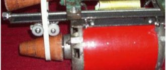
How to make a throttle yourself
In order to make a transformer from a choke yourself, you need to calculate the number of turns per volt for the existing core. Then the inductor is carefully disassembled and the process of winding the future transformer is carried out. During assembly, it should be taken into account that the gap that was present in the throttle before disassembly must be eliminated.
You can also make a transformer from chokes. The amount of material used directly depends on the purpose of the invention.
Technological process for replacing a choke transformer
Reinstallation and removal of the choke transformer is carried out in the following order:
- After receiving permission to carry out the work, the power supply is removed.
- Next, the protective casing is dismantled.
- After carrying out the above operations, the insulating cable entry pipe should be freed from the soil and the cable stock should be cleaned.
- Next, unscrew the nuts of the mounting bolts and remove the cover of the cable rack.
- Then the cable cores are disconnected and the cable is pulled out from the insulating pipe post.
Installation of electric traction connectors bypassing is carried out in the following order:
- One connection of the throttle plug-jumper and the rail is dismantled on both sides of the insulating joints, to do this, unscrew and remove the lock nut on each of them, unscrew the nut to the end of the thread, knock the plug out of the rail, and disconnect the jumper from the rail.
- Install connector plugs into the vacated holes. Screw the nuts onto them and secure them until they stop.
Installation and assembly of the choke transformer is carried out in the reverse order of dismantling work.
Important! Before installation, you should carefully read the instructions and work procedure. It is necessary to take into account the installation location of the choke (at the supply end or in sections) depending on its type and purpose.
Safety precautions during work
When installing a track choke transformer, you should adhere to the safety and labor protection rules:
- The work is carried out by a team, one of whose members is responsible for monitoring the movement of trains. Before carrying out work, safety instructions should be given.
- Replacing the inductor transformer at the end of the rail circuit from which the power comes is done when the voltage is removed by disconnecting the wires from the transformer winding in the relay cabinet of the signal installation or removing the arms on the cross-connect stand of the electrical centralization. After the voltage is removed, using measuring instruments, you need to make sure that there is no voltage in the previously disconnected wires. At the point where the electric current is disconnected from the power supply, a prohibitory poster “Do not turn on! People are working."
- All excavation work is carried out wearing gloves.
- When carrying out loading and unloading operations, it is prohibited to be in the area of cargo manipulation.
Important! Before starting work, an uninterrupted circuit for the flow of reverse traction current should be ensured by installing temporary jumpers of the required cross-section, bypassing the insulating joints.
If a train approaches during work, you should leave the site at a safe distance in advance and remove the tool.
In emergency cases, it is necessary to provide first aid to the victim, call an ambulance and report the incident to the head of the site.
Connecting any portable meters to electrical circuits that are energized is allowed only if there are special insulated tips on the wires of the devices.
Naturally, a team that has not completed a course of special training and instructions on TB is not allowed to work.
Features of operation and connection
TD 500 is a model designed to regulate voltage parameters when performing electric welding of metal products. The device is widely used due to its low cost and ease of operation .
The productivity of the device is sufficient for welding metal elements. The device is intended for performing manual arc welding with coated electrodes. According to the passport, the TD-500 is a single-phase electric current converter with increased magnetic field dissipation. The air gap depends on how much the movable windings are shifted.
The current regulator is actuated by moving the lead screw, which is rotated manually. In this case, the windings are shifted by screwing into the nut.
Increased magnetic field dissipation occurs due to the placement of the windings. One moves together with the screw, the other is fixedly fixed at the attachment point.
The transformer is classified as a group of standard devices that are mass-produced . The device is highly powerful, so its connection must be made using large cross-section cables, otherwise the connecting wires will heat up and melt under the influence of current.
The connection must be made by a certified person. Special attention is paid to the places where cables are connected, since they are the points where the likelihood of breakdowns is highest. If there is no tight contact between the cable ends and the copper terminals, these places are susceptible to overheating due to insufficient contact area. This malfunction results in a short circuit.
To avoid this, you need to twist the mating points as tightly as possible, but without pinching them, and constantly monitor the tightness of the fit.
To prevent short circuits, the location of the transformer should not be wet.
An important point is cooling, since the TD 500 has some problems with heating and removing excess heat . In addition to a separately installed forced ventilation system, it would be useful to find an installation location with natural ventilation or a cool zone. When performing outdoor work, such places are shaded and open to the wind.
It is not recommended to exceed the operating parameters of the device specified in the instructions; act only within the permissible intervals. We must not forget about the maximum periods of continuous operation. For TD 500 this parameter is 60%. that is, out of 10 hours, the device should only work for 6, and be turned off for 4 hours.
Important! If malfunctions or breakdowns occur during operation, you should immediately disconnect the device from the power supply. A new connection may only be made after the causes of the malfunction have been completely eliminated.