The heating system cannot be called an engineering communication, which is simple in design and balancing. Each of its components performs a specific function, and the absence of any element can lead to interruptions in the operation of heating equipment, as well as to a significant decrease in its energy efficiency. In our project “A HOUSE IN A YEAR” you can see how we made the heating system. In this article, among other things, we will understand the basic principles of balancing a heating system with the help of specialists from the GRUNDFOS company.
As for balancing: it ensures stable operation of the system and guarantees compliance with the specified temperature regime in all heated rooms.
Having a professional design for the heating system is the key to its effective functioning. For those who are not going to spend time and money on heating design, we will give several recommendations on its creation and proper configuration.
In this article we will consider the following questions:
- What elements should be included in the piping of simple and multi-circuit heating systems.
- Installation rules and sequence of arrangement of the main elements of the harness.
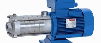
- What functions should a modern circulation pump have?
- How can you balance your home heating system?
The listed topics will be discussed using the example of closed heating systems. After all, they have complex piping and a large number of elements that make it possible to ensure a stable thermal regime in the room.
Wiring of simple heating systems
The piping of a heating boiler is usually called all the elements of the system that are installed between the boiler and the heating circuits (meaning radiator and underfloor heating circuits, as well as hot water supply circuits).
A heating system can be called simple if it contains one direct circuit. A direct circuit means a line into which coolant is supplied from the boiler without changing the initial temperature. Some radiator heating systems are simple. They can be single-pipe, double-pipe or mixed. The most practical type of simple radiator heating is a two-pipe system based on a supply and return line.
And if its balancing is done correctly, such a system will ensure uniform heating of the radiators along the entire heating perimeter.
Evgeniy Kruchinin Engineer of the Household Equipment Department of GRUNDFOS LLC
An unbalanced heating system will make itself felt almost immediately. Pipes will make noise due to suboptimal flow rates, rooms will be either too hot or too cold, and heating bills will be 20% higher every time.
Let's consider the main elements of the system and their functions.
Main functions of automation units for pumps
A large number of suburban areas are equipped with wells and boreholes. The owners strive to have an autonomous source of water. More often this is a technical resource that is used for irrigation. But such water is also used quite actively as drinking water. In terms of chemical composition, it can significantly exceed tap water, especially if the intake is carried out from a great depth.
The automation operation scheme for water supply pumps and wells is not inferior in efficiency to central systems.
In order for the process to be technically optimal and meet the requirements, many people prefer to buy automation for a well pump.
Based on functionality, mechanisms can be divided into two types:
- automatic control of water supply;
- protective system.
Regulating mechanisms allow you to adjust the required flow. When watering - more intense, for domestic needs, including for supply to heating and household appliances - less force.
A protective mechanism prevents damage to the unit in the event of a significant voltage drop. In situations where the water level has changed, pumping is impossible; when turned on, dry running occurs.
A well-established scheme for the operation of a well and automation for water supply pumps is not inferior to central systems in terms of operating efficiency and even in some respects surpasses them. When using an individual source, interruptions and shutdowns are eliminated; electricity costs are less than paying for the amount of water consumed from the central water supply system. In cases where it is possible to use it as drinking water, the advantage becomes even more significant.
Based on functionality, automation is divided into regulating water supply and protective.
Expansion tank
A closed expansion tank is a tank equipped with a rubber membrane that divides the device into two parts (the lower half contains the coolant, and the upper half contains inert gas). When the temperature in the heating system increases, part of the coolant enters it, thereby smoothing out the pressure difference in the supply and return lines.
The expansion tank is built into the return line in front of the circulation pump (if the pump is placed in front of the tank, it will constantly pump coolant into the expansion chamber).
The tank can be installed in close proximity to the heating boiler. Additional shut-off valves (ball valve) installed in front of the tank entrance will make it easy to disconnect the tank from the system if there is a need to repair or replace it.
Start-up of the pumping station
In order to put the pumping station into operation, it and the supply pipeline must be completely filled with water. For this purpose, there is a special filler hole in the housing. Pour water into it until it comes out. We screw the plug into place, open the tap at the outlet to the consumers and start the station. At first, the water comes with air - air pockets that formed when filling the pumping station come out. When water flows in a smooth stream without air, your system has entered operating mode and you can operate it. If you have added water, but the station still does not start - the water does not pump or flows in jerks - you need to figure it out. There are several possible reasons:
- there is no check valve on the suction pipeline lowered into the source, or it does not work;
- somewhere on the pipe there is a leaky connection through which air leaks;
- The resistance of the pipeline is too high - a pipe of a larger diameter or with smoother walls is needed (in the case of a metal pipe);
- The water level is too low, there is not enough power.
To prevent damage to the equipment itself, you can start it by lowering a short supply pipeline into some kind of container (water tank). If everything works, check the line, suction depth and check valve.
Security group
The security group consists of three elements connected in series or to one housing:
- An emergency safety valve that allows you to discharge excess coolant when the pressure in the system increases. The discharge can be placed in a transparent container (for example, a plastic bottle). This will make the device safer and will notify you that an emergency has occurred (even if no one was home).
- Automatic air vent - removes air from the coolant, which, if present in the heating system, can render it inoperative.
- Pressure gauge - allows you to visually monitor the coolant pressure in the supply line.
The safety group crashes into the supply line immediately at the outlet of the heating boiler. This is done in order to primarily protect the boiler, which has the highest temperature.
If it is possible to install protection directly on the boiler body, then this feature of the heating device should be used.
The safety group is installed strictly vertically, and it must be located above the level of the heating boiler.
There should be no shut-off valves between the safety group and the boiler. After all, if you accidentally close the tap, thereby isolating the protection from the rest of the heating, you can cause a rupture of the boiler or other elements of the system.
Evgeniy FORUMHOUSE user
Ignorance, inattention, haste, fatigue and other human factors can lead to accidents. For example, I changed the pressure gauge, but forgot to turn the tap, etc.
An additional automatic air release valve should be installed at the highest point of the system. Air will definitely enter the system during its refueling (refueling), and this device will help stabilize the operation of the system, avoid stagnation of the coolant due to air accumulation and extend the life of the circulation pump.
krim FORUMHOUSE user
We install the air vent at the top point of the system. It doesn't have to be on the security group.
Installation of the mixing unit
Before installing the distribution unit, it is necessary to determine its location. It can be installed in the room where the floor will be installed, or in the boiler room of a private house.
It is possible to mount the unit directly on the wall or in a metal cabinet, which is mounted into a recess made in the wall. It is equipped with adjustable guides and doors. A collector placed in such a cabinet looks aesthetically pleasing, but it is not cheap. It is important that all electrical appliances are grounded. And also access to the device was free.
The mixer should be mounted at the top point of the system, this will simplify the release of air from it.
The pumping and mixing unit is installed in the following sequence:
- A niche is prepared in which the manifold cabinet is placed.
Making a niche for the closet
Installing a cabinet
- The mixing and distribution unit is installed in the cabinet.
We fasten the pumping and mixing unit
- The corresponding pipes from the boiler are connected to the manifold ball valves.
Connect the collector to the supply
- The floor contour pipelines are screwed to the outlets of the comb.
Connecting the floor pipeline
The heated hydraulic floor structure has been installed, you can check its quality for leaks. Only after this, the screed is poured and the finishing material is laid.
System recharge
Closed-type heating systems are equipped with outlets for recharging the circuit with coolant. If water is used as the coolant, the return heating circuit can be connected directly to the water supply. The replenishment will be done through shut-off valves and a mud filter (a softener filter will also be useful here).
A pressure gauge will help track the pressure difference in the forward and return lines.
If antifreeze is used as a coolant, then a special branch is made in the circuit for pumping antifreeze. Also, do not forget about the coolant drain taps, which cut into the lowest point of the system.
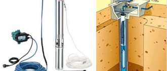
Well pump kit
Submersible pumps for meeting domestic needs are designed to work in wells Ø 75-100 mm. Models are distinguished by power, pressure, performance and type of drive (single-phase, three-phase).
The standard configuration of pumping equipment is as follows: a pump plus a power cable.
This arrangement may be sufficient if the device is intended to be used at the dacha for watering the garden.
To organize water supply at home, the devices are equipped with a control panel and additional equipment:
- automation unit;
- pressure gauge;
- pressure switch;
- hydraulic accumulator;
- check and drain valves;
- filter elements;
- deep-well pump protection unit;
- electrical voltage stabilizer.
The control package consists of a relay and a set of sensors that monitor the state of the installation and allow it to operate autonomously without human intervention.
The membrane accumulator is designed to equalize the pressure of the water supply system.
A protection sensor and voltage stabilizer support the operation of the mechanism during emergency situations, including:
- low water level in the well;
- phase failure;
- power surges;
- short circuit;
- pump overload or underload;
- engine overheating.
Radiator control and shut-off valves
Heating radiators are equipped with half-turn ball valves, which allow you to completely shut off or, conversely, open the coolant supply to the radiator. Taps are placed at the entrance to the device. Sometimes thermostatic radiator valves (without presetting) are used instead, which automatically shut off the coolant supply when the room temperature exceeds the set values.
The listed devices cannot be used to balance the system. Balancing valves (valves) and thermostatic valves with presetting serve these purposes.
Well features
When the well is completely ready for operation, you can turn on the pump and start pumping water out of it, the quality and quantity of which can vary greatly. The main influence on this is exerted by several indicators, namely: 1. Depth
Water with different properties is extracted from different depths. These depths of occurrence of natural resources are usually called horizons. In cases with water wells, four such horizons are distinguished:
- A simple well with a depth of up to 20 meters.
- Well-well , having a parameter of up to 30 m.
- Sandy horizon , which is located at a distance of 50 - 70 m below the ground surface level.
- Artesian horizon . Its depth can be 100 meters and below.
We recommend: How to heat a room evenly using a heat exchanger
The choice of the depth of the future water source will depend on many factors, some of which are:
- purpose of the source,
- required amount of water,
- presence or absence of permits,
- price,
- geodetic conditions of the area,
- depth of the aquifer.
2. Diameter
This indicator directly depends on:
- parameters of drilling equipment,
- characteristics of the future pump,
- affordability of the process,
- intended purpose.
The larger the diameter, the more expensive the well will cost, the larger the diameter of the pipes required for its installation.
The positive side will be high productivity. When choosing a drilling diameter, you should always be guided by the principle of sufficient necessity. At the same time, it is recommended to make a small margin in the parameters, since it is not always known for certain:
- how much water the future source will provide;
- how quickly it will recover;
- how the well will behave after a long time.
3. Well flow rate
This definition refers to the maximum amount of water that can be pumped out of a well in one hour. This parameter not only depends on the power of the installed equipment, but also on the recovery ability of the source itself. It is rare that large volumes of water can be endlessly pumped out of a well or a drilled artesian canal. The more powerful the equipment, the sooner the water will be pumped out. The more often pumping is done, the smaller the volumes will be. Weak equipment can work for a long time, pumping up to the top as much water as is restored in the well. Determining the exact flow rate is a complex process and unnecessary for individual use sources.
4. Volume of water consumed
This indicator depends on the flow rate of the source and the needs of its user. If water consumption is less than the well can provide, then problems with water shortage can be avoided.
The amount of water in the well, in addition to its depth and width, may depend on:
- season,
- pumping intensity,
- parameters of the equipment used.
Correct calculation of consumption will allow rational use of valuable natural resources. This will additionally allow you to:
- save energy,
- extend the life of the pump,
- provide higher quality and cleaner produced water.
A competent and careful approach to the arrangement of an autonomous source of water supply for a site will give its owner the opportunity to access the most valuable natural resource, which must be treated with respect and love. This will definitely have positive consequences in the near and distant future.
Filters
Mud filters are essential elements of modern heating systems. When installing mud filters, it is important to take into account the rules for their installation, since it is during installation that mistakes are often made. It is also important to remember to clean them from time to time. Sometimes it is enough to install one dirt filter into a closed heating system. It is installed on the section of the main line through which all the coolant passes. Such a place could be, for example, the area in front of the main circulation pump.
Basic rules for installing mud filters:
- It is preferable to install the filter on horizontal sections of the pipeline.
- When installing the filter, it is important to ensure that the direction of movement of the coolant coincides with the marks marked on the body of the device.
- The tap branch, equipped with a screen, nut (or drain cock), should be located at the bottom.
- The dirt filter must be installed in a place that is easily accessible for maintenance.
- Shut-off valves (half-turn valves) should be installed at the inlet to the filter, as well as at the outlet.
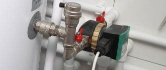
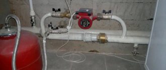
Pump installation diagram
To perform its functions, household circulation equipment, regardless of the manufacturer, must be correctly installed on a pipe or shut-off and control valves.
Fastening is done using union nuts. This fixation option will allow you to remove it if necessary, for example, for inspection or repair.
When choosing a circulation pump model, you need to pay attention to its ability to function in different positions. Vertical placement of the device reduces its power by up to 30%
Correct installation of all elements of the heating system ensures uniform heating of the entire line.
When installing the circulation pump, the following rules must be observed:
- It is allowed to install the device on any section of the pipe. The pipeline can be located horizontally, vertically or inclined. However, the rotor axis must be in a horizontal position. Therefore, installation “head down” or, conversely, up is impossible.
- It is worth paying close attention to the location of the plastic box where the power supply contacts are located - they will be on top of the body. Otherwise, they may be flooded with water in an emergency. To do this, you will need to unscrew the fastening screws on the casing and turn it in the required direction.
- Observe the direction of flow. It is indicated by an arrow on the device body.
With all its weight, the pump presses on the body of the ball valves located nearby. This should be taken into account when choosing fittings. High-quality parts are equipped with a powerful body, which during operation will not become cracked from daily stress.
Piping a multi-circuit heating system
If the heating system has two or more circuits (we are talking about systems with heated floors, with an indirect heating boiler, etc.), in addition to the main pump, each circuit is equipped with a separate circulation pump and additional shut-off valves.
Heating circuits that require temperature control are equipped with the devices presented below.
Areas of use
The need for a pumping and mixing unit arises if the coolant is water. Let's find out in what cases this happens.
- If the water heated floor is connected from central heating - since the heating of water in the centralized system exceeds the required level for underfloor heating.
- When connected from a boiler that does not operate with a return flow of +55 and below - these are all solid fuel boilers and those operating on gas.
- If the main line consists of two or more circuits with different temperatures (warm floors with radiators).
Automatic faucets
Three-way mixing valves are devices that allow you to automatically reduce/regulate the temperature in the supply line by mixing cooled coolant from the return line into it. The fact is that the boiler sends coolant with the same temperature to all heating circuits. At the same time, heated floors have strict requirements for maintaining temperature conditions, and the temperature in the heating radiator circuit is usually higher than in the heated floor circuit. Mixing valves allow all circuits of the system to reach the desired temperature.
Rules for connecting to power supply
The circulation pump is powered. The connection is standard. It is recommended to install a separate power supply line with a surge protector.
To connect, you need to prepare 3 wires - phase, neutral and ground.
You can choose any of the connection methods:
- through a differential machine device;
- connection to the network together with an uninterruptible power supply;
- power supply to the pump from the boiler automation system;
- with thermostat regulation.
Many people wonder why complicate things, because connecting the pump can be done by connecting a plug to a wire. This is how the pumping device is plugged into a regular outlet.
However, experts do not recommend using this method due to the risk of unforeseen situations: there is no grounding and a safety device.
A circuit with a differential machine is used for so-called wet groups. A heating system constructed in this way ensures a high degree of safety for wiring, equipment and people.
The first option is not difficult to assemble yourself. It is necessary to install an 8 A differential circuit breaker. The wire cross-section is selected based on the device rating.
In the standard scheme, the power supply is carried out to the upper sockets - they are marked with odd numbers, the load - to the lower ones (even numbers). Both phase and neutral will be connected to the machine, so the connectors for the latter are designated by the letter N.
To automate the process of stopping the circulation of the coolant when cooling to a certain temperature, an electrical circuit is used to connect the pump and thermostat. The second is mounted in the supply line.
At the moment when the water temperature drops to the specified value, the device disconnects the electrical supply circuit.
In order for the thermostat to turn off the circulation process at the right time, it is installed on a metal section of the pipeline line. Due to poor heat conductivity of polymers, installation on a plastic pipe will result in incorrect operation of the device
There are no difficulties in supplying electricity through an uninterruptible power supply; it has special connectors for this. A heat generator is also connected to them when there is a need to provide electricity.
If you choose the method of connecting the pump to the boiler control panel or automation, you will need good knowledge of the power supply system or the help of a professional.
Collectors
The collector groups separate the main heating circuits, as well as individual circuits of the underfloor heating system.
This is what a heated floor manifold assembly with a three-way mixing valve looks like.
In addition to the above cases, collector units are used in radiant heating systems.
A lot of controversy arises about where to install circulation pumps in collector systems, as well as in simple heating systems - on the supply or return? Here's what experts say about this.
Evgeniy Kruchinin
By and large, it makes no difference where the circulation pump is installed - in the supply or in the return. It is important that the pump is easy to maintain - this is perhaps the main criterion for choosing an installation location. An exception is the case when the temperature of the coolant in the heating system may exceed the maximum temperature for which the circulation pump is designed. In this case, it is recommended to install the pump on the return line, where the coolant temperature is lower.
Multi-circuit heating is a cumbersome engineering communication with many elements that must be correctly calculated, installed and combined into a single system.
In order to make the piping scheme simpler, more reliable and aesthetically pleasing, experts recommend using pump groups (quick installation groups), which are completely ready for installation and are sold already assembled. They include circulation pumps and piping elements that may be needed in one case or another.
Pump groups can be used as part of simple and complex heating systems.
Evgeniy Kruchinin
Pumping groups are easy to install and operate. All strapping elements included in the quick installation group have already been selected according to their characteristics and assembled into a single structure. Moreover, each pump group produced is necessarily tested by pressure testing at the factory, which makes it a much more reliable solution than pump piping assembled “from scratch” from the market. This greatly simplifies life for both installers and residents. In addition, compact pumping groups, having an aesthetic appearance, fit perfectly into the interior of a modern boiler room.
Principles of installation and balancing
When choosing a pump group, it is necessary to keep in mind the location of the supply and return lines of the heating circuits. This primarily applies to multi-circuit systems. Some pumping and mixing groups have a universal design, in which the connection of lines can be moved to any convenient side. But also, in the range of manufacturers there are complexes with the ability to connect the supply only on the left or on the right.
As a rule, pumping groups can be connected to boilers of any configuration, taking into account the location of the pipes (floor, wall, double-circuit, etc.). There are models designed only for wall-mounted boilers, which are placed under the heat generator. Here the connection to the pipeline is located at the top of the device.
A separate pumping group is installed for each heating circuit. They are connected to the boiler using a manifold comb, into which the supply and return pipes of each circuit are alternately connected. Some collectors have a hydraulic arrow in their design, which performs the function of balancing flows. When automatic control is connected, pump groups operate in conjunction and are controlled by a single panel.
The main element of the group is the circulation pump. There are complexes in which a pumping device of a certain power is initially installed. But there are also models with free space for installing a pump. In this case, you can independently select a device of the required level of performance. The installation length of pumps is standard for most manufacturers and is 130 mm, 180 mm, 220 mm. Typically, pump groups use a hydraulic device with a wet rotor, where the incoming liquid acts as a lubricant.
An important step for the effective functioning of the heating system is its balancing. This is necessary in order to eliminate excess energy consumption and extend the service life of the equipment. The task is performed by adjusting thermostatic valves, thermal imagers and thermometers to the required volume of passage of the working fluid in different parts of the system. If the circulation pump is equipped with automation, then balancing occurs quite simply and quickly in automatic mode.
Thus, when choosing a pump group, you need to focus on the parameters of the heating system. The performance of the device, ease of operation and comfort in living quarters depend on this. In this case, it is worth contacting a specialist with professional knowledge in this field.
Balancing the heating system
An important step towards effective balancing is the correct choice of circulation pump. For example, circulation pumps that have the function of automatically adjusting pressure and flow will constantly regulate the pressure difference between the supply line and the return line. Thanks to this, there is no need to integrate additional piping elements into the system (bypass valves, differential pressure regulators, bypasses connecting the supply to the return, etc.).
Most often, balancing heating systems is carried out in three ways:
- Calculated – takes into account the design coolant flow in each section of the system.
- Balancing based on the actual temperature of heating devices (radiators, underfloor heating circuits, etc.).
- Electronic balancing is the most accurate way to ensure the system is set up correctly the first time. This is done using a special mobile application, shut-off valves and adjustment functions built into the circulation pump.
Before starting balancing, it is necessary to check and clean all dirt filters built into the heating system, and also make sure that there is no air in the system.
Features of equipment installation
There are two options for installing the pump:
- The self-priming device is mounted next to the water source. A special submersible hose is lowered into the water at one end and attached to the pump at the other.
- The submersible device is attached to the pipe. If it is a flexible hose, then an addition to the fasteners can be a cable, which is attached with one end to the pump, and the other to any stable element with a well. A flexible installation option is preferable, as it allows you to adjust the immersion depth of the unit. The pump is completely immersed in water. Most of these devices do not tolerate dry operation well. Therefore, it is always worth monitoring the level in the well or purchasing a pump with a float switch that will protect the device in the event of no or critically low water levels.
It is recommended to install a check valve on the pipe itself, which will keep water in the system.
The algorithm for installing submersible equipment includes the following points:
- All pipes are installed. If the pump will be installed on a rigid pipe, then it is recommended to place a small piece of flexible hose between it and the main channel for moving water into the house, which will dampen engine vibrations.
- The following are connected to the device: - cable, - electrical wire, - hose.
- The pump smoothly lowers to the bottom of the well.
- When the unit touches the bottom, the entire structure should be raised to a height of half a meter to a meter from the point of contact.
- The cable must be firmly secured, the wire must be connected to the network, the hose must be connected to the rest of the system and placed in the fastening channels.
- It is recommended to provide the upper hole of the well with a cover to prevent foreign objects and dirt from entering the system.
The electrical connection should only be made to a grounded source using a circuit breaker according to the following diagram:
Electrical connection diagram for a well pump
When installing the pump, you may need metal fluoroplastovie bushings; their options can be viewed here https://cema-bearing.com/metalloforoplastovie_vtulki/.
Balancing according to design calculations
The easiest way is to balance the system using the data specified in the heating project. The essence of balancing, regardless of the chosen method, comes down to setting the required coolant flow in various parts of the system. The flow is regulated using balancing valves or thermostatic valves with presetting.
The balancing valve has its own gradation. In this case, the different positions of the control valve correspond to a certain volume of coolant that is capable of passing through the device per unit time at a given pressure.
If you have a project for a heating system, you can properly balance it quite simply: by setting the coolant flow rate in accordance with existing calculations.
Evgeniy Kruchinin
But it is important to take into account the fact that often design calculations differ from the actual parameters of the heating system. For example, the hydraulic resistance of a heating circuit can be easily changed by adding or removing an element from the system. But, in general, a good and correct project is a rarity for private houses.
Therefore, even if there is a project, the balancing methods presented below do not lose their relevance.
Conclusion
The presented electrical diagrams for connecting a well pump are the simplest, but most common in the private sector for home water supply. However, it is worth noting that for large houses and powerful pumps, more complex automation and startup schemes for water supply pumps are used.
©Elesant.ru
More articles
- Do-it-yourself water drilling for water supply to a house, cottage, or dacha
- Types and choice of surface pump for a private house
- Choosing polyethylene pipes for external water supply at home
- Choosing a water supply scheme for your home: do-it-yourself water supply for your home
- Choosing a well pump is easy
- Sources of water supply systems for a private home
- How to install a well for a private house
- External and internal water supply of a country house
- Water supply to the house: external water supply of a private house
- Laying a trench for the external water supply of a private house
- Calculation of a surface pump: how to calculate the pressure of a surface pump
- Calculation of a well pump: formula and example of detailed calculation
- Private house water supply systems
- Automatic water supply station: selection and installation of a water supply station
- Insulation of the external water supply of a house: materials and methods of insulation
Temperature balancing
To balance the system by temperature, we will need the already familiar balancing valves (or thermal heads with presetting) and an electronic thermometer for non-contact measurement of surface temperature.
Balancing begins with the balancing valves on the last and penultimate radiator being fully opened. The coolant flow rate on the first, as well as on subsequent radiators from the boiler, is set to minimum values (with an increase in flow rate as the radiators move away from the boiler).
For example, if there are 8 radiators installed in the system, and the balancing valve screw is adjusted within 4.5 turns, then the first radiator from the boiler is first completely closed, then its balancing valve is unscrewed by 1.5 turns. The regulator of the second radiator is unscrewed by 2 turns, the third by 2.5, and so on. The coolant flow on the last and penultimate radiator in most cases remains maximum. If possible, adjustments are made only on those radiators that are closest to the boiler (the distance is measured from the beginning of the supply line).
It is not recommended to unscrew the regulator less than 1.5 turns. After all, if you turn down the throttle opening of the valve too much, the device will quickly become clogged with scale or other debris.
Fine adjustments are made according to the readings of the thermometer. The main goal of balancing in this case is to achieve approximately the same temperature difference at the inlet and outlet of each radiator.
If the temperature difference at the inlet and outlet of a single radiator reaches 10ºС, it is not recommended to close its balancing valve even more.
And one more thing: noise in the radiator during operation of the heating system indicates that the coolant flow should be reduced.
Criteria for selecting a well pump
When choosing this device, you should consider the following:
- Operating point of the unit This indicator determines the intersection of the device parameters with the properties of the well. It is known that water in wells does not have a constant level. These indicators are indicated in the passport of the water source. If there is no such document, you can take measurements yourself. It is recommended to take several measurements to obtain an average water level. It is important that their average indicator coincides with the passport characteristics of the purchased equipment, which operates in the range from 70 to 120% of its nominal parameters.
- Types of well pumps Knowing the depth of the water source, you can determine what type of unit is needed - surface or submersible.
Fundamental differences between pump types:
- A self-priming surface device will allow you to raise water from a depth of up to 9 m. This option is suitable for small wells. Its advantage is the possibility of external fastening and easy accessibility in case of need for repair or dismantling. The negative thing is that this unit freezes in the cold and requires filling the suction channel with water before starting work. These devices are divided into: - centrifugal without an ejector, - self-priming with an ejector.
- The submersible unit will allow you to work at any depth. This type is the most suitable in any situation. It is more difficult to install, but such a pump works all year round.
Read more about choosing a well pump based on key technical characteristics and installation conditions.
Control automation for a submersible pump
The automation system that regulates the operation of the pump consists of several elements. The main one is the control relay, which is supplemented by the electrical part. Depending on the features of the configuration, there are two principles of operation of the devices.
The control automation for a submersible pump consists of a control relay and an electrical part.
Regulation of water pressure in the pipeline. Valid when water is supplied from a well and the system has a hydraulic tank. After the first rise, it fills the container and is then fed into the home system. Automation operating according to this scheme has a sensor with electrodes.
Some units (usually intended for wells) are equipped with special floats to control the amount of water. It should be noted that the price of submersible pumps for wells with automation of this type is quite high, but the devices are in demand. Regardless of the method of controlling the filling of the accumulator, all tanks have an emergency drain, which, if necessary, will reduce the pressure in the tank. A positive characteristic of the operation of just such a control system is the stable operation of the pump, ensured by constant hydraulics.
Level control. This is done using commands. A certain pressure is set on the relay, the pump turns on and off depending on its change. A similar scheme is actively used in private areas; it also requires the presence of a membrane tank. As positive characteristics of such a scheme, it should be noted the relative ease of installation and the low price of the automation. The ideal picture is slightly spoiled by the inaccuracy of readings and the short service life in a system with vibration pumps.
Note! When using a pressure level control circuit, the relay can be installed in the power circuit of the pump.
The pressure switch can be installed in the power circuit of the pump.
How to raise water to a height without a pump: video, description
Do not rush to assess the conditions for cultivating soil without electricity as extreme. It is in such situations that a considerable number of gardeners find themselves who have developed plots of land in vacant lots and other unclaimed areas. Ingenuity and useful experience, which many share on the Internet, make it possible to organize water supply without electricity.
There are quite a few such pumping methods. The most accessible ones include the following:
An Archimedes screw is a device consisting of a cylinder and a screw placed inside it with a handle for rotation.
- Application of the Archimedes screw. The device consists of a hollow cylinder and a screw placed inside it with a handle for rotation. The system must be lowered into the source at an angle. A mechanically driven screw takes in water and delivers it upward.
- Using a hydraulic ram. The method was invented by the Montgolfier mechanic. It is based on the kinetic energy of water: the flow passing through a rigid pipe is blocked, and water flows through a check valve into the hydraulic tank located above. The tank is equipped with a fitting at the bottom, onto which a hose is placed that supplies water to the consumer.
To get more information on how to raise water to a height without a pump, it is worth watching the video:
On a note! When creating a mechanical water supply device, it should be taken into account that the most effective and affordable method is a piston system.
Well pump with automation: operating features, connection
Is there a difference between borehole and sump pumps? Yes, but it would be more accurate to say that pumps with certain technical characteristics are used to pump water out of a well. These are monoblock centrifugal devices, where the engine, water intake elements and pipe are located in one housing.
The well pump is installed at a depth of no more than 25 m. It has a rather low performance. The pump for an automatic well should be positioned so that it does not drift along the water layer. It is also necessary to eliminate vibrations of the unit, as they will raise all sorts of unwanted particles from the bottom.
It should be noted that the protection against solid particles entering and sticking to the wheel blades in well pumps is weak. Therefore, when pumping contaminated water, they quickly lose their rated performance.
Well pumps, that is, centrifugal ones, differ from vibration pumps in the way they are protected from running dry. It consists of the following: when the intensity of the water flow entering the pump decreases (when air enters), the current strength of the device’s electric motor also decreases. The sensor reacts to the current situation by giving a signal to turn off the unit.
Connecting a submersible pump for a well is carried out according to the same scheme as for a well pump.
The connection diagram for a submersible pump for a well is almost the same as for a well pump. The only difference is in the method of fixation: the borehole is attached to the head; for a well, a metal frame is made, a hole is made in it, into which the cable is inserted.
How to properly assemble and connect the collector
Install the frame - the collector is mounted in a horizontal position directly on the wall, or in a cut-out niche. The only condition for installation is free access to the heating pipe arrow. It is also possible to install a manifold cabinet yourself
The cabinet will allow you to hide the wiring from prying eyes, which is especially important if a bathroom or hallway is used as a boiler room.
Connection to the boiler - coolant supply is from below, return is from above. Ball cut-offs must be installed in front of the frame.
A pump group is installed immediately behind the taps. To maintain the required temperature, the heated coolant is only partially used. The pump not only creates the necessary pressure in the heating system, but also helps to mix cooled water from the floor circuit and heated water coming from the boiler. A bypass valve with a temperature limiter is installed. A distribution comb is installed behind the valve. The distribution of the collector to heated floors is carried out as follows. The pipes going to the heated floor are attached from above, from the heating system from below. If you need to assemble a distribution manifold for a warm water floor with your own hands, shut-off valves with a built-in thermostat are installed in the comb. Practice shows that the best option is to purchase a ready-made structure. Assembling a manifold, even by a professional, and adjusting the valves independently is a labor-intensive process that requires certain skills and experience. Connecting a warm water floor collector requires the use of special components. Compression fittings are used, consisting of a support sleeve, a clamping ring and an intermediate brass nut. After installation, the collector is configured.
Pressure testing of the collector - after completing the installation work, it is necessary to check the sealing of the connections. To do this, the completed collector group is connected to a pump (pressure tester). Using a pressure tester, pressurize the system. The water circuit is left under pressure for a day. If the pressure readings have not changed, it means that the installation of the heated floor manifold with your own hands was done correctly and the mixing unit is ready for operation.
At first glance, installing the collector yourself seems quite simple. But as practice shows, it is better not to start installation without the necessary tools and special skills.
Direct connection diagram
You have a boiler, after which all safety fittings + a circulation pump are installed. In some wall-mounted boiler versions, the pump is initially built into its body.
For floor-standing units you will have to install it separately. From this boiler, the water is first directed to the distribution manifold, and then disperses through the loops. After which, having completed the passage, it returns through the return line to the heat generator.
With this scheme, the boiler is directly adjusted to the desired temperature of the TPs themselves. You don't have any additional radiators or radiators here.
What are the main features worth paying attention to here? Firstly, with such a direct connection, it is advisable to install a condensing boiler. In such schemes, operation at relatively low temperatures for the condenser is quite optimal
In this mode it will achieve its highest efficiency
In such schemes, operation at relatively low temperatures is quite optimal for the condenser. In this mode it will achieve its highest efficiency.
If you use a regular gas boiler, you will soon say goodbye to your heat exchanger.
The second nuance concerns solid fuel boilers. When you have it installed, for direct connection to heated floors, you will also need a buffer tank.
It is needed to limit the temperature. It is very difficult to directly regulate the temperature with solid fuel boilers.