Technical characteristics of the PVG-8 press
- Productivity, pairs of parts per hour……. 250
- Maximum cutting force, kN (kgf)….. 78.4 (8000)
- Striker stroke (adjustable), mm……… 0 – 30
- Striker reach, mm…………….. 715
- Dimensions of the working area of the striker, mm……. 350X450
- Distance between the planes of the striker and the table, mm.... 80—180
- The largest perimeter of cut parts on a non-metallic plate, mm.... 1100
- Maximum operating pressure in the hydraulic system, MN/m2 (kgf/cm2)……………… 5.8 (60)
- Oil volume in the oil tank, dm3………… 65
- Hydraulic drive electric motor power, kW… 1
- Front size, mm …………… 1100
- Depth, mm……………….. 900
- Height, mm………… 1440
- Weight, kg…………………. 1000
Description of the operation of the PVG-8 shoe press
The press consists of a frame with a hammer mechanism, a hydraulic drive and electrical equipment.
Bed 1 (Fig. 1 at the beginning of the article) and the press table are one. There is an insulating pad 2 on the table, on which a steel cutting plate 3 is placed, connected through contact 4 and an electrical wire 5 to the press control electrical network.
When cutting material with sharp cutters, a non-metallic cutting plate or an aluminum plate with an insulating film is installed on the table instead of a steel plate 3.
Inside the frame there are hydraulic drive mechanisms 6, and on its right side in a niche there is an electrical panel 7. The removable front shield 8 and the right shield 9 serve to enclose the hydraulic drive and the electrical panel.
The frame has a bracket 10 with a palm button 11 and a signal light 12 to indicate the press is ready for operation.
There is also a push-button station 13, two removable auxiliary tables 14, a bracket 15 for hanging leather and a bolt for grounding the press bed.
The bracket 10 carrying the palm button 11 can be rotated about a vertical axis. This makes it possible to set the palm button in a position convenient for the worker. To rotate the bracket 10, release the union nut and, after installing the bracket, tighten it again.
Under the striker there is an end process contact (limit switch) 16, the height of which is adjusted with a screw 17 and a nut 18.
Limiter 1 (Fig. 2), consisting of a bar, a leaf spring and a rubber gasket, attached with bolts 2 to a rib inside the frame, is a shock absorber that limits the movement of the striker when retracting it from the working area to the right and softens the impact of the key 3, rigidly fixed to the rolling pin 4 .
Fig.2 Cross section of the PVG-8 press
The press is installed level so that the plane of the table is strictly horizontal, and the bed fits tightly to the floor with its entire base.
Malfunctions and their elimination
The PVG-8-2-O press has almost the same design as the PVG-8 press. Therefore, all faults are identical. Since the design of the press has been improved (automatic rotation), additional malfunctions in the operation of the hydraulic drive are possible due to additional spool, valve, and other parts.
In electronics, the most common faults are related to faulty wiring (poor contacts, short circuits to the housing). The control board works reliably.
Striker mechanism
pin 4 with a cantilever striker 5 secured by a nut 6 at its upper conical end is installed in the vertical cylindrical guides of the frame The hammer by handle 7 rotates freely together with the rolling pin in the cylindrical guides of the frame. This allows you to punch out parts when installing the cutter anywhere on the punching plate.
A shock-absorbing plate 9 with a metal contact plate 10 is attached to the lower plane of the striker by two strips 8, which, through a cutter and a technological contact, closes the press control circuit after cutting through the material.
Inside the rolling pin 4 at the bottom there is a working cylinder 11 connected to it via a thread. The piston 12 of the cylinder is freely seated on the rod 13. The lower end of the rod has a thread and is rigidly connected to the frame with a nut 14. The upper end of the rod is connected through a rod 15 to a handwheel 16, which serves to set the striker in height and also to adjust its stroke.
The cavity of the cylinder 11 communicates through the hole in the rod 13 with the oil line of the press hydraulic system. When oil enters cylinder 11 under piston 12, the cylinder is lowered along with rolling pin 4 and hammer 5 to cut out the material.
Piston 12 does not move in the vertical plane when the press is operating.
The safety washer 17 limits the downward movement of the rolling pin 4 and the striker 5 if the set stroke value of the striker is greater than permissible.
Springs 18 are loosely attached to the rod 15, which are compressed when the rolling pin 4 moves downwards. When, after cutting out the material, the spool opens a free passage for oil from the working cylinder to drain, the springs 18 will raise the rolling pin 4 with the hammer 5 to the upper starting position. The thrust ball bearings 19 and 20 receive axial loads from the springs 18, from the mass of the rolling pin, the hammer and other parts, and thus make it easier to turn the hammer manually. If it is necessary to change the angle of rotation of the striker, it should be moved to the right until it stops, unscrew nut 6 and disconnect the striker from the rolling pin. Then you need to rotate the striker relative to the rolling pin, set it to the required position and secure it again with nut 6. To eliminate the gap between the conical surfaces of the striker and the rolling pin, nut 6 must be tightened periodically.
To lubricate the guides of the rolling pin 4, oil is supplied by a spool through a lubrication valve 21, connected by a tube 22 to a hole in the frame. The lubrication valve serves to regulate the amount of oil supplied to the guides and consists of a housing 23, a spring 24, a ball 25 and an adjusting screw 26.
Oil leaks from the working cylinder are drained through rubber hose 27 through the filter back to the oil tank.
Hydraulic press drive
The hydraulic drive consists of a vane pump 1 (Fig. 3), a working spool for opening and closing the corresponding holes of the hydraulic system, controlled by an electromagnet 2, a safety valve 3 to protect the hydraulic system and press parts from overload.
Fig.3. Scheme of the hydraulic drive of the PVG-8 press
The hydraulic drive mechanisms are located on the hydraulic panel 4, which is the cover of the oil tank 5. For ease of installation, the pump is attached to the hydraulic panel through an adapter flange 6 with bolts 7.
The pump is driven by an electric motor 8, which is attached to the plate 9, and the latter is attached to the cover 4 of the oil tank 5 with bolts 10.
The torque from the electric motor shaft to the pump shaft 1 is transmitted through a sleeve-pin coupling located under the plate 9. The coupling consists of two coupling halves 11 and 12, connected by pins 13 with rubber rings 14.
Thrust ball bearing 15, taking on the load from the weight of coupling halves 11 and 12, unloads the shafts of the electric motor and pump.
Oil line 16 connects pump 1 to the spool, and adapter tube 17 connects the pump to safety valve 3.
The spool consists of a body 18, fixed to the hydraulic panel using covers 19, a rod 20 connected by a pin 21 to an electromagnet 2, a spring 22, a thrust washer 23 and a strip 24.
Oil is supplied to the working cylinder of the press through oil line 25 through a spool with a glass 26 and through a tube 27 inserted into the hole of the rod 13 (see Fig. 2).
Oil line 25 (see Fig. 3) is connected to the spool and cup 26 with fittings 28 and union nuts 29 and 30.
The mating surfaces of the rod and cup 26 with tube 27, as well as the oil pipe 25 with fitting 28, are sealed with rubber rings 31.
The brake ring 32 keeps the rod from spontaneously unscrewing during press operation.
To fill oil, there is a hole in the hydraulic panel with a filter 33 inserted into it.
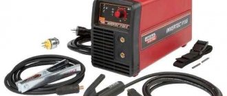
Recommended brands of oils are industrial 20 or industrial 30. Before filling the tank with oil, turning on the electric motor of the pump is not allowed, since when operating without oil, the pump will fail within a few seconds.
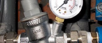
The required oil level in the tank during operation is maintained by oil indicator 34. The design of the press provides the possibility of pumping out the oil with pump 1 to the required level, as well as draining it through the hole in the lower part of the oil tank. In order to pump oil out of the tank with a pump, you need to unscrew plug 35 and connect a special oil line to the hole in the spool body. When determining the pressure in the hydraulic system, a pressure gauge is connected to the same hole.
The oil pressure in the hydraulic system should not exceed 6 MN/m2. The pressure is changed by rotating the adjusting screw 36 of the safety valve 3, for which you first unscrew the cap and loosen the corresponding lock nut. After adjustment, the pressure gauge is disconnected from the spool body 18 and plug 35 is screwed into the hole.
The operating oil pressure is established by trial cutting of parts. The pressure in the hydraulic system is slowly increased until clean cutting of parts along the entire perimeter is achieved. In this case, the maximum length of the perimeter of the cutter blade when working on a metal plate should not exceed 900 mm. When cutting on a non-metallic plate, the longest perimeter length of the cutter should not exceed 1100 mm. If by adjusting the pressure the cutting of parts along the entire perimeter is not achieved, then check the quality of the cutters and the cutting plate, as well as the parallelism between the working planes of the plate and the striker.
Press work
When you press the KP button (Fig. 4), the magnetic starter P turns on the electric motor through contacts P2 and connects the step-down transformer Tr to the network.
The electrical and hydraulic circuits of the PVG-8 press are given below.
Fig.4. Diagram of electro-hydraulic press PVG-8
The electric motor drives the NL pump, which pumps oil without pressure from one cavity of the BM oil tank to another through the oil pipeline I-III through the open drain hole of the spool ZR. There is no pressure in the hydraulic system. Cutting out parts on a metal plate can occur in the “without slowdown” and “with slowdown” modes. The difference between these modes is that the press switches to the return stroke of the striker.
Cutting out parts when the press is operating in the “without deceleration” mode is the most rational, since in this mode the specific pressure on the cutters does not increase with a decrease in their perimeter, and the loads on the cutting and shock-absorbing plates and press parts are close to optimal.
In this case, before starting the press, the 1VT changeover switch is set to the “no slowdown” position, in which its contacts are open. When you press the palm button KB, the 1RP relay is turned on and, with its closing contact 1RP1, closes the circuit of the EM electromagnet, which moves the rod of the working spool ZR upward. The rod closes the drain hole, and oil flows through oil line I - II into the working cylinder of the CR, moving it down along with the rolling pin and the hammer. Oil is supplied through tube IV to lubricate the rolling pin guides. At the same time, relay 1RP with contacts 1RP2 bypasses the HF button. In this case, the relay and electromagnet remain turned on for the entire time the striker moves down, regardless of whether the HF button is held in the on position or not.
After cutting out the material, at the moment the cutter blade comes into contact with the cutting plate, the technological contact 1KT is closed and power is supplied to the intermediate relay 2RP. Relay 2RP with its opening contacts 2RP1 and 2RP2 breaks the circuits of relay 1RP and the electromagnet EM, the coil of which is de-energized, and the spool rod ZR spring returns to its original position, opening the free passage of oil from the pump IL and the working cylinder CR to drain. The springs installed inside the rolling pin, compressed when the striker moves down, are released and move the rolling pin with the striker and cylinder up to the stop. When the 2RP relay is turned on, the closing contacts 2RP3 close and ensure that the 2RP2 relay is turned on, and therefore the off position of the EM electromagnet and the 1RP relay, if the contacts of the HF palm button are closed after the striker returns to its original position. This eliminates the possibility of spontaneous restart of the press.
To prepare the press control electrical equipment for the next work cycle, you need to release the KV button and thereby de-energize the 2RP relay. To protect hydraulic equipment and press parts from overload, a gearbox safety valve is connected to the hydraulic system.
The operation of the press on a metal plate in the “with deceleration” mode and its switching to the return stroke of the striker differs from the operation in the “without deceleration” mode in the sequence of operation of the elements of the electrical circuit after cutting out the material. In this mode, the press has time to develop great force, as a result of which the quality of cutting out parts from materials of high humidity and low density improves. But at the same time, the load on the cutter, shock-absorbing and cutting plate, hammer and other parts of the press increases.
In this case, before starting the press, the 1VT rocker switch is set to the “deceleration” position, in which its contacts are closed. Relay 2RP, which receives an electrical impulse when the technological contact 1KT is closed, cannot directly break the circuit of the electromagnet EM, but with its opening contacts opens the circuit of relay 1RP, which, when turned off, turns off the electromagnet with its closing contacts 1RP1.
Since the electromagnet, after closing the technological contact through the cutter, turns off with a delay equal to the time it takes to release one intermediate relay, the press has time to develop greater force and travel a longer distance during this time.
When cutting out shoe parts on a non-metallic plate (block), the 1VT rocker switch is set to the “no slowdown” position.
The sequence of operation of the elements of the electrical and hydraulic systems when cutting out parts on a non-metallic plate (block) is the same as on a metal plate in the “without slowdown” mode, but the switching of the press to the return stroke of the striker after cutting out the material is carried out by the 2KT technological contact, located outside the cutting room slabs (decks). When cutting material on a non-metallic plate, the cutters in the set must be the same height.
Hydraulic press device. The initial state
So, the original hydraulic press looked something like this:
Hydraulic press – electrical panel, main switch
The main switch is locked with a key, which of course does not exist, so we had to disassemble everything and simplify the design.
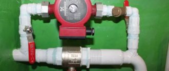
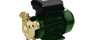
Press drive of the oil station (hydraulic pump). There is no nameplate on the electric motor, but in size it is definitely less than 1.5 kW.
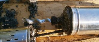
Press - rotary hammer-rolling pin
In this photo, on the front board there is a handle by which the striker is turned. On this handle there is a power button, which is pressed by the operator of the cutting press. The same button, parsed:
German press – turning on the cut on the rolling pin
The cutting force is adjusted using the knob on the hammer (see one photo above). The handle adjusts when the limit switches are pressed (with wheels, first left, then right):
German press – limit switch adjustment
Hydraulic press system:
Press - hydraulic diagram
The hydraulic circuit of the press is controlled by the electromagnet (solenoid) MIS, when turned on, the cut is started, that is, the press hammer begins to move downwards. The electromagnet MIS is in the center of the photo.
Press electronics before restoration:
Internal structure of the press electrical cabinet. You can see the unscrewed plugs.
Internal structure of the electrical cabinet of the press_2. You can see the remaining starters and what remains of the removed parts.
Setting up the press
When cutting out parts on a metal plate, the impact mechanism is adjusted as follows.
Place the cutter on the metal plate and use the flywheel (see Fig. 1) to lower the striker down until the contact plate comes into contact with the cutter. Technological contact 16 is set by rotating nut 18 so that the gap between contact 16 and the lower plane of the striker is 3-4 mm, after which screw 17 is secured with a locking screw. Then the hammer is raised by the flywheel by 10-12 mm and by pressing the palm button 11 several test runs of the press are performed with and without a cutter. In the first case, the striker must return to its original position after contact of the contact plate with the cutter, in the second - rise after its contact with technological contact 16.
If parts are cut out on a non-metallic plate, then the shock-absorbing plate and contact plate are replaced with an aluminum plate 10-12 mm thick and a new stop is installed, which ensures that the striker stops in such a position that the distance from the aluminum plate to the deck is 15 mm.
Using a flywheel, the striker is raised and fixed at such a height that the gap between the cutter mounted on the deck and the aluminum plate is 4-5 mm. Using nut 18, process contact 16 is moved until it comes into contact with the striker.
Then the striker is raised by 10-12 mm, several test cuttings of the parts are made, and at the same time the height of the technological contact 16 is additionally adjusted so that the part is cut out along the entire perimeter, and the cutter blade cuts into the deck no more than 0.5 mm. After adjusting the height of the striker, screw 17 is locked.
If normal cutting of parts does not work, check the pressure in the hydraulic system.
The second technological contact 2KT (see Fig. 4) when cutting material on a metal plate is used as an emergency limit switch that limits the downward movement of the striker in the event that the press is turned on without a cutter installed on the cutting plate.
A mechanical stop limits the downward movement of the striker if, due to a malfunction in the electrical or hydraulic system, the 2KT process contact does not operate.
The electrical circuit of the press is designed in such a way that low-voltage voltage is supplied to open process contacts only when the palm button is turned on. This eliminates the possibility of electric current passing through the worker’s body if a technological contact is accidentally closed by hand.
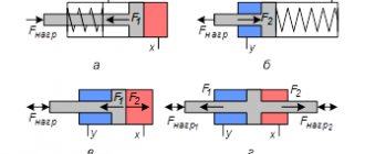
Hydraulic control circuit on the relay
At the request of reader Ivan (see comments dated July 25, 2016), I am posting a control diagram for two hydraulic valves. Description of the algorithm in the comments.
Electrical circuit for hydraulic control
Relay and valve coils are powered by 220 V.
Buttons SB1, SB2 and relays KA1, KA2 - with additional NC blocking contacts.
The simplest circuit, on the basis of which all relay logic is assembled.
If you have any questions, please leave a comment.
Problems with the PVG-8 press. Repair and troubleshooting
1. When you press the palm button, the firing pin remains motionless. Reasons: the distribution spool ZR is jammed; the EM electromagnet coil has burned out; The connecting pin between the spool valve and the electromagnet core has jumped out or broken. The limit switch wire is shorted to the housing.
2. After cutting out the material, the hammer does not return to its original position. Reasons: there is no contact between the cutting plate and the 1KT technological contact; there is no contact at the moment of cutting out between the striker and the 2KT process contact, the spool spring ZR has broken or weakened; The spring of the rolling pin, designed to return it to its original position, has broken.
3. When cutting with a large-perimeter cutter, the material is not cut out and the hammer does not return to its original position. Reasons: gearbox safety valve is incorrectly adjusted; IL pump damaged; the piston rings in the working cylinder of the CR are worn out; loose connections of oil lines; There is a crack in the pump housing.
4. The electric motor of the press is switched off by a thermal relay during operation. Reasons: the pump rotor jammed due to oil contamination; tighten the thrust bearing of the flywheel pulley; The shafts of the electric motor and the IL pump are installed out of alignment.
5. The pump does not create the required pressure. Reasons: air got into the system; there is a crack in the pump housing; the roughness of the stator working surface is high; The blade has failed or is stuck in the rotor groove.
6. The pump operates with shocks and noise. Blades jamming occurs due to low quality oil and the formation of clots in it or as a result of foreign objects getting between the blades and the rotor.
7. The rolling pin of the press is not lubricated. Reasons: the tube is clogged; The lubrication valve is faulty or clogged.
The appearance and operation of the PVG-8 press can be seen in the video:
The principle of operation of the relay circuit (option 3)
1. When the left and right buttons are closed, KM1 turns on. Contacts KM1.1 close, MIS turns on.
2. When the limit switch is pressed, KM2 is turned on. Then, almost simultaneously, this is what happens.
- -Contacts KM2.1 duplicate the limit switch and hold power to KM2.
- -Contacts KM2.2 open, KM1 turns off, contacts KM1.1 open, MIS turns off.
- -KM2.3 contacts turn off, MIS turns off.
3. After the MIS has turned off, the limit switch contacts open. However, the KM2 will remain on until one or both buttons are released by the operator. The cycle is over.
Possible modifications to this electrical circuit:
1. The phase is supplied only to the MIS through the appropriate contacts, the remaining circuits are powered through a 12 or 24 V transformer. This is necessary for safety reasons, since when the START buttons are pressed, phase voltage is present at the process contact of the limit switch! Voltage acts through the coil of the KM2 starter and can lead to electric shock to operating personnel.
2.N.O. is additionally introduced into the MIS circuit. contacts that are closed by the “START” buttons (additional pairs of contacts). When cutting, the process contact (limit switch) closes to the press body. It must be pre-set to the required height required to cut through with optimum quality.
Press limit switch PVG-8-2-0
The striker stroke is equal to the distance between the bottom plane of the striker and the limit switch.