Industrial processing of metals includes several dozen methods and techniques for changing the shape, volume and even the molecular structure of a material. Electrospark processing of metals is one of the most common technologies for working with metals, characterized by high accuracy and productivity. Using electric spark machines you can:
- cut metal;
- drill holes of microscopic diameter;
- increase defective areas of parts;
- produce jewelry work with precious metals;
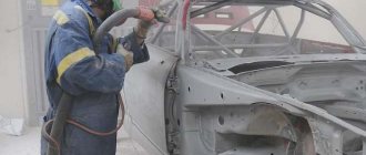
- strengthen the surface of products;
- grind products of the most complex shapes;
- remove stuck broken drills and cutters.
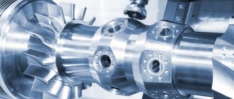
Many industrial machines have been created based on the electric spark method of metal processing. This is high-precision and expensive equipment that only large enterprises specializing in metalworking can afford to buy.
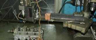
Electric spark machine
But sometimes electric spark machines are also required in workshops or workshops where their services are required from time to time. To do this, you can buy an industrial device with somewhat limited capabilities (functionality within the most popular operations), or build a homemade electric spark machine. This is quite possible even at home, not to mention enterprises that include turning and electromechanical shops or areas.
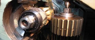
Operating principle of an electric spark machine
The processing of metals by the electric spark method is based on the property of electric current to transfer a substance during breakdown. At high voltage and direct current (1-60 A), the anode (positively charged electrode) heats up to a high temperature in the range of 10-15 thousand degrees Celsius, melts, ionizes and rushes to the cathode. There, due to electrical interactions, it settles.
To prevent a full-fledged electric arc from occurring during operation, the electrodes are brought closer together only for short moments, lasting a fraction of a second. During this time, a spark occurs, destroying the anode and growing the cathode. The treated area is heated and exposed to electric current for milliseconds, while the neighboring areas and the underlying layer do not have time to warm up and their structure is not disturbed. The problem of borderline states does not arise in principle.
If cutting or drilling is required, the working tool serves as the cathode, and the workpiece serves as the anode. When building up, strengthening the surface or restoring the shape of a part, they change places. For these types of processing, special machines have been created, each of which performs its own operations.
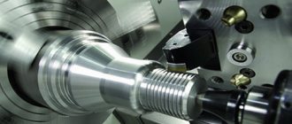
The tools used in EDM installations are brass or copper-graphite electrodes, which conduct current well and are inexpensive to manufacture. With their help you can cut and drill the hardest alloys. To prevent the cathode metal from settling on the electrode and increasing its size, the process occurs in a liquid medium - the liquid cools the melt droplets, and it cannot settle on the electrode, even if it reaches it. The viscosity of the liquid determines the speed of movement of material particles, and they cannot keep up with the current. The metal settles in the bath as a sediment and does not interfere with the further passage of current.
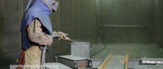
When increasing the surface of parts or strengthening, metal is transferred from the anode to the cathode. In this case, a positive electrode is fixed to the vibration installation, serving as a metal donor, and the part is connected to the negative pole. No water or oil is used in this process, everything happens in the air.
Electric marker for metal. How to make an engraving?
Specific methods of electric spark processing of conductive materials include engraving their surface using a low duty cycle electric discharge. Metal electric markers produced for these purposes are compact, energy-saving devices, and therefore are widely used for both industrial and domestic purposes.
Device characteristics
When the interelectrode gap between the cathode, which is a marking tool (sometimes called an electrographic pen) and the anode, the metal surface, breaks down, erosion of the anode metal occurs, as a result of which a set of holes is formed.
Their shape and location are determined by the trajectory of the electric marker across the metal and the intensity of the electrical impulse.
In order for the thermal energy of metal evaporation to be concentrated in a limited volume, the surface of the processing zone is wetted with a liquid dielectric, which uses ordinary mineral oil.
In addition, the oil reduces the force of separation of a manually moved electrode from the surface being treated, preventing a short circuit in the interelectrode gap. The anode blank is connected to the general electrical circuit of the device using a clamp. You cannot use water for electrical marking, and especially not aqueous solutions of salts.
As a result of point erosion, a pattern, production mark or any other mark up to 1...2 mm deep can be formed on the surface. In addition, the marked surface is visually different.
Since the result of a single act of electrical erosion is a hole where the bottom is formed by periodic electrical impulses, the treated surface is always matte, and therefore is especially noticeable on ground, polished or cold-rolled metal.
The electrographic marking process runs stably with the following operating characteristics of the device:
- Operating voltage, V – 30…140.
- Processing current, mA – 40…300.
- Duty cycle, s-1 – up to 100.
- The cathode material is tungsten wire with a diameter of up to 1 mm (it is also possible to use high-carbon steel type 65G or 60S2).
In practice, the power consumption of the device depends on the marking depth and the electroerosive ability of the anode metal, but usually does not exceed 20...50 W.
The delivery set also includes a vibrator that generates vibrations of the working head of the device with the required frequency.
In order to ensure electrical safety, electric markers for metal are equipped with thermal sensors that respond to overheating.
Operating principle of an electric marker
The metal surface to be marked must be thoroughly cleaned of grease and oxide films.
The latter noticeably worsen the conductivity of the metal, which forces an increase in the voltage in the interelectrode gap.
The discharge results in a low duty cycle, but with coarser dimples, which deteriorates the quality of marking. The spark discharge power is controlled by a step switch.
The following geometric characteristics of the hole are considered optimal for these purposes:
- Width – 0.2…2.0 mm;
- Depth – 0.15…20 µm;
- The speed of marker movement on the surface is up to 10 mm/s.
The kit of some models of electric markers for metal also includes a steel plate, equipped with fasteners for fixing the part that is being marked.
The sequence of working with an electric marker for metal is as follows. The device is connected to a household power supply with a voltage of 220 V and a frequency of 50 Hz through an autonomous power supply. The part to be marked is attached to a metal plate using an alligator clip.
In order to protect the operator’s eyes, the vibration device is covered with a special filter, after which the electrographic pen is brought to the surface, which is covered with a thin (2...3 mm) layer of liquid dielectric.
First, a test discharge is performed, during which the optimal speed of movement of the electrographic pencil along the surface of the product is established. As the pen moves, new processing areas are wetted with the dielectric.
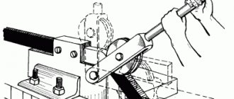
To set up an electrographic marker for metal, you must perform the following steps:
- Set the vibrator frequency to the required mode. To do this, use (depending on the size and manufacturer of these devices) one of the following methods: either optimize the sound signal (as the oscillation frequency decreases, the permissible value of the interelectrode gap increases), or adjust the frequency by changing the brightness of the signal light.
- The switch sets the required current value. It is usually maximum for metals with low thermal conductivity (most non-ferrous metals and alloys), and less for aluminum, steel or cast iron.
- By moving the electrode-tool along the required trajectory of movement, marking is made. The overall dimensions of the symbols have no restrictions.
- When working with an electric marker, it should be remembered that increasing the voltage and current of the electrical discharge beyond the required speeds up the wear of the electrode and does not lead to a significant increase in the productivity of the process. Wear is especially intense in the event of a short circuit (occurs when there is a lack or absence of dielectric fluid on the marked surface of the product). For guidance, you can use standard wear values of 0.05...0.2 mm per mark.
- To correct an erroneously applied mark, the surface must be sanded.
The use of an electric pencil requires the operator to have certain skills and experience.
The duration of continuous use of an electric spark marker is not fundamentally limited, although if the device operates for more than 30...40 minutes, the pulse generator unit warms up.
Replacement of a worn cathode-tool is carried out with the device turned off. The electric metal marker should not be used in rooms where the relative air humidity exceeds 75%.
Advantages of electric markers and their standard sizes
Preservation of the marketable appearance of products after electrical marking is ensured by:
- No distortion of the product surface;
- The ability to brand thin surfaces without the risk of deforming them;
- Effective use of the process regarding any conductive materials;
- Convenience of applying brands, the range of which is not limited in any way;
- When using a tungsten electrode with selective metal transfer, anti-corrosion treatment of the surface of steel products is simultaneously carried out.
Models of the most popular electric markers are shown in the table
| Device model | Overall dimensions of the hole, microns | Limit character size, mm | Voltage, V | Current, mA | Power consumption, W | Company, country | Approximate price, rub. |
| EVZ-021 | 10×10 | Up to 50 | 220…230 | 200 | 20 | Josef Solnar (Czech Republic) | 10000 |
| EVZ-022 | 20×50 | Is not limited | 220…230 | 450 | 50 | Josef Solnar | 12000 |
| AG25/3 | 20×20 | Same | 4 | 5000 | 25 | ArgloAG (Switzerland) | 23500 |
| AG50/6 | 20×50 | Same | 6,5 | 6500 | 50 | ArgloAG | 25000 |
Technological indicators
An electric spark installation, depending on the operating mode, can ensure the accuracy of the result within a wide range. If high performance is required with relatively low requirements for surface condition (class I and II), then currents of 10-60 A are used at voltages up to 220V. In this case, electric spark erosion can remove metal from the cutting or drilling zone in a volume of up to 300 mm3/min. With higher accuracy class values - VI and VII, productivity decreases to 20-30 mm3/min, but lower currents are required, no more than 1 A at voltages up to 40 V.
Such a wide range of adjustments shows that electric spark processing of metal can be used in various fields, both for the production of large series of parts and for one-time work, including jewelry.
A feature of the use of electric spark installations can be considered the ability to strengthen parts of various configurations. A thin layer of a stronger alloy or metal is applied to the surface of the workpiece without heating the base to a greater depth. This allows you to preserve the metal structure of the base product and significantly change the properties of its surface. In some cases, base viscosity and high surface hardness are required, or vice versa. Only an electric spark machine can solve this problem.
Electric spark machine diagram
Metal processing by the electric spark method is very common, so it is very difficult to consider all types of equipment and models of specific installations. They are all united by common structural elements:
- DC source;
- capacitor;
- vibrator;
- mode switch.
A design operating in an electric spark mode may differ in a number of characteristics that allow it to work with a particular material, but the general principles of constructing a working circuit are the same.
The battery of capacitors is coordinated with the mechanical movement of the electrode, the discharge occurs at the moment of maximum approach of the working surfaces. Relaxation pulse generators determine the maximum charge of the capacitor at the maximum amplitude of deviation from the approach point. After the spark discharge, the capacitor has time to charge fully.
DIY electric spark machine
One of the main parts of an electric spark installation, which you can implement with your own hands, of course, subject to all safety rules, is given below. It should be noted that this is only one of many designs that can be used in machine design.
Approximate diagram of a spark discharge generator
The work table of the machine must be equipped with an oxide removal system (continuous supply of oil or kerosene). They reduce the likelihood of depositing an oxide film on the surface of the part and, as a result, stopping sparking. For breakdown, reliable electrical contact is required. As a basic option, you can use a bath filled with liquid.
The electrode is a brass or copper wire of the required diameter, which is fixed in a clamp. The clamp, in turn, is a part of the vertical rod of the crank mechanism, which is driven by an electric motor. The frequency of reciprocating movement of the electrode is selected depending on the characteristics of the material being processed.
All conductive parts and cables must be properly and reliably insulated, and the installation itself must be grounded. You can see how homemade homemade installations work in the video:
It should be noted that homemade machines will never equal the capabilities of industrial ones, for example the ARTA series. They may be suitable for the production of handicrafts or use as one of the types of hobbies, but they are not “up to par” for working in a workshop or metalwork shop. Not to mention that the complexity of the electrical circuit and the need for precise coordination of kinematics and capacitor discharge make them very difficult to adjust.
Abstract on the topic “Electric spark and electric pulse processing of metal”
Department of "MANAGEMENT IN ROAD TRANSPORT"
“Natural Scientific Foundations of Modern Technologies”
Project topic:
"Electric spark and electric pulse processing of metal"
INTRODUCTION
Electrotechnology includes electrical methods of metal processing, which have received great development over the past decade.
Electrical processing methods are those types of processing in which the removal of metal or a change in the structure and quality of the surface layer of a part is a consequence of the thermal, chemical or combined action of an electric current supplied directly (galvanic connection) to the part and the tool. In this case, the conversion of electrical energy into other types of energy occurs in the processing zone formed by the interacting surfaces of the tool and the workpiece.
Electrical processing includes electrical erosion, electrochemical, combined electrical erosion-chemical and electromechanical processing methods (Scheme 1).
With electroerosive processing methods, metal removal and changes in the surface properties of the part are the result of the thermal action of electric current.
In turn, electroerosive methods of processing metals according to their intended purpose differ into the methods by which they are carried out:
a) electroerosive dimensional
metal processing (removing metal and giving the workpiece a given shape and size);
b) electrical discharge hardening
or
coating
(changing the properties of the surface layer).
Currently, the following main methods of electrical discharge machining are known and used: electric spark, electric pulse
and
electrical contact
.
the anodic-mechanical
should also be included in this group , since electrochemical metal removal (anodic dissolution) is used only in finishing modes and, moreover, not in all cases of using this method.
Scheme 1. General classification of electroerosive methods of metal processing.
As can be seen from diagram 1, electric spark
and
electric pulse
methods allow both metal removal and hardening;
anodic-mechanical
and
electrical contact
- only metal removal.
Depending on the method of processing or hardening, we can talk about electric spark, electric pulse
,
electrical contact
or
anodic-mechanical
dimensional processing or hardening.
The given definitions and classification allow us to consider the electrical processing of metals as an independent branch of electrical technology.
With the advent of electrical processing methods, it turned out to be, in principle, possible to carry out using electrical technology methods the entire complex of operations necessary to transform a workpiece into a finished part, including its heat treatment.
Electroerosive methods do not exclude mechanical processing, but complement it, occupying their specific place corresponding to their characteristics, namely: the ability to process conductive materials with any physical and mechanical properties and display the shape of the tool in the product. Consequently, the use of electrical discharge processing methods will develop with an increase in the hardness and viscosity of the processed materials, with the complication of the shape of the part and the processed surfaces (cavities of complex configuration, holes with a curved axis, holes of very small diameter, thin and deep slots of simple and complex shape, etc. .), finally, with the improvement of the technical and economic indicators of electrical discharge processing methods - increasing productivity, surface cleanliness, accuracy, tool life and reducing the energy intensity of the process.
Particularly promising is the use of electrical methods for processing parts made of hard alloys, heat-resistant steels and special difficult-to-process alloys, which are increasingly used due to increasing pressures, temperatures and speeds in machines and devices.
Individual elements of varieties and particular applications of electrical discharge machining of metals have been known for a long time. For example, cutting metals with the application of electric current (the so-called electrofriction
cutting, similar in design and parameters to
electrical contact
processing) was used about 70 years ago; surface hardening with a carbon electrode using electric current according to the method of D.N. Dulchevsky was proposed in 1928, etc.
the electric spark machine in 1943 by B. R. and N. I. Lazarenko
method and V.N. Gusev -
anode-mechanical
method.
These methods were supplemented in 1948 by the new use of electric contact processing (sharpening according to the method of engineer M. E. Perlin), which was further developed in the work of the Kharkov Electrotechnical Institute, Kharkov Bearing Plant (processing of balls according to the method of engineer B. P. Hoffman) , KhTZ named after Ordzhonikidze (processing of tracks), Research Institute of the Ministry of Shipbuilding Industry (processing of propellers), etc.
Development of electric spark
and
anode-mechanical
methods went through the creation of numerous experimental designs of adapted and special electrical discharge machines, automatic regulators and the development of new technological operations. The technical characteristics of these methods - productivity, tool life, energy intensity, ease of use - have not undergone any significant changes for the better during this period.
In electric spark
The method based on the use of dependent (capacitor) relaxation pulse generators has practically exhausted the possibilities for further increasing productivity, reducing tool wear and energy consumption. Fundamentally new technical solutions and the abandonment of capacitor circuits turned out to be necessary. The first steps in this direction were made in 1950 at the Design Bureau of the Ministry of Machine Tool and Tool Industry (KB MSiIP) in the field of creating new pulsed current power supplies (independent pulse generators) for stitching and copying work, and by the Odessa Polytechnic Institute in the field of developing pulsed current sources current for processing with a rotating tool in soft modes (for making needle files).
A new processing method based on the use of independent voltage and current pulse generators is called electric pulse processing.
Since 1951 electric pulse
the method was developed in close collaboration by three organizations: the MSiIP Design Bureau, the Laboratory of Electrical Processing Methods of the Experimental Research Institute of Metal-Cutting Machine Tools and the Department of Electrical Machines of the V. I. Lenin Kharkov Polytechnic Institute.
Electropulse
The processing method when carrying out piercing and copying work made it possible, in comparison with
the electric spark
method, to increase the rate of metal removal under harsh conditions by 5-10 times, with the possibility of its further increase, to reduce tool wear by 5-20 times and energy intensity by 2-3 times.
The information presented in this work generally characterizes the current state of technology, technology and industrial use of electrical discharge machining of metals. The greatest attention is paid to electric pulse
a processing method that has better technical and economic indicators and a wider range of applications than
electric spark
.
Of the various applications of electric pulse
processing, mainly the more studied stitching and copying works are presented, which are the most difficult to implement and are more universal in technological capabilities.
Electrical processing of metals and its variety - electrical discharge machining - represent an independent branch of electrical technology, which is at the initial stage of development.
PHYSICAL CONDITIONS FOR IMPLEMENTING DIMENSIONAL ELECTRO-EROSIVE MACHINING
To ensure high-quality dimensional processing of metals through the use of the thermal effect of electric current, the following three basic conditions must be met:
1. Electric current energy must be supplied to the treated area in the form of a pulse of sufficiently short duration (localization of elementary metal removal in time).
With a continuous supply of energy, the processing accuracy is lost, a defective fused sublayer appears, the surface cleanliness deteriorates and one of the main technological qualities of electrical processing methods is lost - the display
(copying) the tool shape into the part.
An example of processing with a continuous supply of energy is cutting or burning holes with an electric arc; in this case, the accuracy and cleanliness of the surface at the cut site is unacceptable for dimensional processing.
2. The area of the part to which the energy pulse is applied must be small enough (localization of elementary metal removal in space).
In order to remove metal when applying an energy pulse to a large area, it is necessary to correspondingly increase the pulse energy, which will lead to an increase in the elementary removal. The greater the elementary metal removal, the worse, naturally, the surface cleanliness and the lower the processing accuracy.
If the energy impulse is kept unchanged with an enlarged elementary section, then metal removal may not occur at all, since the supplied energy will not be enough to melt the elementary removal.
3. Energy pulses must be supplied to elementary areas of the volume of metal to be removed continuously and with sufficient frequency (localization of the processing process in time). This condition ensures the continuity of the process and obtaining the required productivity.
These three conditions are satisfied to varying degrees by electrical processing methods based on the thermal effect of electric current.
VARIETIES OF ELECTRO-EROSIVE MACHINING OF METALS
Electrical processing of metals can be divided into three groups.
To the first
The group based on purely contact energy supply includes
electromechanical
processing.
Since a purely contact energy supply does not satisfy the three conditions of dimensional processing, as a result of which metal removal is not achieved, with electromechanical
In this method, metal is removed with a cutter, the cutting edge of which is at the same time a contacting surface.
An alternating current is supplied to the cutter and the workpiece, which heats the part at the point of contact. Electrical contact heating serves only the purpose of reducing cutting forces and can be replaced by other heat sources - an arc, an acetylene torch flame, high-frequency heating, etc.
As calculations and experience show, from an energy point of view, introducing an electric current through a cutter is generally impractical and does not increase productivity or increase tool life. The latter is explained by the fact that, due to small voltage drops at the contact point, to create any significant heating it is necessary to introduce very large currents; in this case, the cutter finds itself, from the point of view of heat removal, in much more severe conditions than the workpiece. Therefore, the cutting edge heats up and the durability of the cutter decreases.
At low currents, the heating of the product is so negligible that it has virtually no effect on the magnitude of the mechanical cutting force.
Second
the group includes processing methods that use energy supply through a discharge channel.
This group includes electric spark
and
electric pulse
methods and intermediate varieties, for example, such as processing with aperiodic pulses on a relaxation generator, which includes elements of both methods.
Third
a group that combines
diode-mechanical
and
electrical contact
methods with all varieties, based on the use of a combined contact-arc energy supply.
Scheme 2. Classification of electroerosive metal processing methods according to energy supply methods.
Scheme 2 shows the classification of methods for electrical discharge machining of metals according to energy supply methods and indicates the varieties known in industry, assigned to one or another method based on the principle of similarity of the greatest number of characteristics. The largest number of varieties is obtained by combining pulsed current sources required when supplying energy through the discharge channel with the relative movement of the electrodes used in combined energy supply. These varieties include the so-called low-voltage electric spark
and
electric pulse
processing of bodies of rotation or processing with a rotating electrode,
anodic-mechanical
processing with pulsed power, etc. Depending on which of the methods prevails in this combination, we can speak, for example, of
electrical contact
processing with pulsed power or
electric pulse
processing with a rotating electrode. The same applies to other combinations of the four main EDM methods.
Let us consider the fundamental differences between the types of dimensional electrical discharge machining within the second and third groups.
Electrospark
and
electric pulse
methods differ, as will be shown in more detail below, in the device for generating pulses, the parameters and shape of the pulse, as well as the polarity of the electrodes.
Diode-mechanical
and
electrical contact
methods differ in the type of current used (in the first case - direct, in the second - alternating, and, less often - direct) and in the type of working medium (in the first case - liquid glass, in the second - air, water, oil, etc. )
The consequence of these differences is, in general, a deterioration in the technical characteristics of the electrical contact
method compared to
the anodic-mechanical one
(lower productivity with the same surface cleanliness, greater tool wear, limited range of processed materials), with more favorable operating conditions and greater ease of installation in general. This also determines various areas of their application.
As follows from the above, regardless of the method of supplying energy, the known electroerosive methods of dimensional processing of metals are based on a single physical nature - the metal is removed as a result of the thermal action of electric current.
The differences lie in the mechanism for removing removed metal and in the technical means that ensure the fulfillment of the three conditions of dimensional electrical processing.
A comparison of specific energy consumption for metal removal by various methods shows that the highest energy consumption occurs during electrochemical dissolution (3.85 kWh/kg),
then during melting (0.35
kWh/kg).
During mechanical processing, specific energy consumption largely depends on the type of processing. So, when grinding it is, on average, 2 kW-h/kg,
planing, drilling and milling 0.20-0.25
kWh/kg,
turning 0.045
kWh/kg.
When comparing these data, it should be borne in mind that the specific energy consumption for electrochemical dissolution and melting practically does not depend on the mechanical properties of the materials being processed, while during mechanical processing, an increase, for example, in the hardness of the material being processed sharply increases the specific energy consumption. It should be noted, however, that the actual specific costs in electroerosive and electrochemical installations are significantly higher than the given data due to the inevitable losses of energy during its conversion and transmission.
From an energy point of view, these data determine the feasibility of using electrical methods for processing conductive materials that are difficult to machine.
Taking into account the mapping (copying) property carried out on electroerosive machines using an extremely simple kinematic scheme and without a power drive, and the possibility of performing a number of special operations that are inaccessible to mechanical processing, it is necessary to expand the expedient scope of application of electroerosive methods to parts made of ordinary materials, but with complex shape that makes them difficult to machine.
Consideration of methods for supplying electric current energy to a tool and part shows that to carry out the required physical process of metal removal, special equipment is needed - a machine or installation that includes the following specific elements:
1) pulse generator;
2) automatic regulator;
3) a working fluid supply system (bath, device for working with irrigation, pumping station, etc., depending on the type and purpose of the machine).
ELECTROTECHNOLOGICAL CHARACTERISTICS
The electrical-technological characteristics of electrical discharge machining methods make it possible to determine, based on the given area, configuration and material of the workpiece, which electrical modes and in what sequence they need to be applied in order to obtain a part with the given dimensions and surface finish, and what the machine processing time will be. Electrotechnological characteristics in electrical processing are similar to cutting modes in metal machining.
We will focus here only on the basic fundamental electrotechnological characteristics and methods for their determination. In order to avoid repetition of information known from the literature, we will present only new directions in this issue in relation to electric pulse
processing, although the methodology and quality side are valid for other types of electrical discharge machining. The method of approach to solving the technological problem of processing a part electrically is very important, since the industry has not yet accumulated sufficient experience in creating electrical technology. In order for this experience to be widely used, a unified methodological approach is necessary.
CHARACTERISTICS AND AREAS OF APPLICATION OF DIMENSIONAL ELECTRIC EROSIVE MACHINING
Let us consider the main technological characteristics and areas of primary application of types of electrical discharge machining of metals.
The given data on productivity, surface cleanliness and energy intensity refer to the processing of areas of various sizes in modes that ensure the absence of areas of melting and coating, i.e. at optimal current densities.
Electric spark method
.
removal
rate at maximum conditions when processing steel is on average 600
mm3/min
and is close to the maximum possible for this method of metal processing.
The specific energy consumption in hard modes is 20-50 kWh/kg
of dispersed metal.
Tool wear in relation to the volume of metal removed reaches 25-120 percent or more. Surface cleanliness in soft modes reaches class 4 (Hsr
= 25-30
µm)
at a removal rate of 10-15
mm3/min.
A further increase in surface cleanliness is accompanied by a sharp decrease in the removal rate.
Thus, when obtaining class 5 surface cleanliness (Нср
= 16-19
μm),
the productivity of the electric spark processing method is less than 5
mm3/min.
The specific energy consumption in soft modes is tens and hundreds of times higher than in hard modes.
When processing hard alloys, the productivity of the process in soft modes is approximately two to three times less than when processing steel, but this results in slightly better surface cleanliness. The use of more severe conditions when processing hard alloys is limited by the formation of cracks on them.
Electrospark
The method is currently mainly used for piercing work, manufacturing cavities of complex configurations, etc. operations, as well as for grinding bodies of rotation.
Electropulse method
.
A number of characteristics of this method are outlined above. Electric pulse
processing has significant advantages compared to
electric spark processing
.
The improvement of the technological characteristics of the new processing method is due to the use of special independent pulse generators. The technological characteristics of the method reported below reflect the results of the first works and do not fully characterize the capabilities of the electric pulse
method.
Performance in harsh electric pulse
stitching and copying machine KB MSiIP with a lamp pulse generator exceeds 5000
mm3/min
when obtaining surface cleanliness outside the class.
The indicated productivity can be increased over the corresponding area to several tens of cubic centimeters per minute by increasing the pulse power. The energy intensity in hard modes is 8-12 kWh/kg
of dispersed metal, the relative wear of the tool reaches
0.2 - 20%.
The surface cleanliness obtained on the specified machine in soft modes corresponds to class 4 (
Hsr
= 25-30 µm) with a productivity of: 6-8
mm3/min
, approximately 2-3 times less for hard alloy. Further reduction of the processing mode to obtain greater surface cleanliness leads to an even greater drop in productivity and increases energy consumption. The given technological characteristics of soft modes have now been significantly improved by using new models of machine pulse generators developed by the Lenin Kharkov Polytechnic Institute, ENIMS and KB MSiIP, but still the problem of a sharp increase in the productivity of the processing process in soft modes cannot be solved